EP0041011A1 - Strömungsmaschine zur Erzeugung elektrischer oder mechanischer Energie - Google Patents
Strömungsmaschine zur Erzeugung elektrischer oder mechanischer Energie Download PDFInfo
- Publication number
- EP0041011A1 EP0041011A1 EP81400784A EP81400784A EP0041011A1 EP 0041011 A1 EP0041011 A1 EP 0041011A1 EP 81400784 A EP81400784 A EP 81400784A EP 81400784 A EP81400784 A EP 81400784A EP 0041011 A1 EP0041011 A1 EP 0041011A1
- Authority
- EP
- European Patent Office
- Prior art keywords
- generator
- power
- converter according
- variation
- receiving shaft
- Prior art date
- Legal status (The legal status is an assumption and is not a legal conclusion. Google has not performed a legal analysis and makes no representation as to the accuracy of the status listed.)
- Withdrawn
Links
- 239000012530 fluid Substances 0.000 title claims abstract 4
- XLYOFNOQVPJJNP-UHFFFAOYSA-N water Substances O XLYOFNOQVPJJNP-UHFFFAOYSA-N 0.000 claims description 13
- 238000004873 anchoring Methods 0.000 claims 1
- 239000007788 liquid Substances 0.000 claims 1
- 230000000750 progressive effect Effects 0.000 description 12
- 238000010586 diagram Methods 0.000 description 7
- 230000008878 coupling Effects 0.000 description 3
- 238000010168 coupling process Methods 0.000 description 3
- 238000005859 coupling reaction Methods 0.000 description 3
- 238000012423 maintenance Methods 0.000 description 3
- 230000010363 phase shift Effects 0.000 description 2
- 230000003068 static effect Effects 0.000 description 2
- 230000003247 decreasing effect Effects 0.000 description 1
- 230000006866 deterioration Effects 0.000 description 1
- 239000013529 heat transfer fluid Substances 0.000 description 1
- 238000010438 heat treatment Methods 0.000 description 1
- 239000002184 metal Substances 0.000 description 1
- 210000000056 organ Anatomy 0.000 description 1
- 239000000843 powder Substances 0.000 description 1
- 229910052710 silicon Inorganic materials 0.000 description 1
- 239000010703 silicon Substances 0.000 description 1
Images

Classifications
-
- F—MECHANICAL ENGINEERING; LIGHTING; HEATING; WEAPONS; BLASTING
- F03—MACHINES OR ENGINES FOR LIQUIDS; WIND, SPRING, OR WEIGHT MOTORS; PRODUCING MECHANICAL POWER OR A REACTIVE PROPULSIVE THRUST, NOT OTHERWISE PROVIDED FOR
- F03B—MACHINES OR ENGINES FOR LIQUIDS
- F03B17/00—Other machines or engines
- F03B17/06—Other machines or engines using liquid flow with predominantly kinetic energy conversion, e.g. of swinging-flap type, "run-of-river", "ultra-low head"
- F03B17/062—Other machines or engines using liquid flow with predominantly kinetic energy conversion, e.g. of swinging-flap type, "run-of-river", "ultra-low head" with rotation axis substantially at right angle to flow direction
- F03B17/063—Other machines or engines using liquid flow with predominantly kinetic energy conversion, e.g. of swinging-flap type, "run-of-river", "ultra-low head" with rotation axis substantially at right angle to flow direction the flow engaging parts having no movement relative to the rotor during its rotation
-
- F—MECHANICAL ENGINEERING; LIGHTING; HEATING; WEAPONS; BLASTING
- F03—MACHINES OR ENGINES FOR LIQUIDS; WIND, SPRING, OR WEIGHT MOTORS; PRODUCING MECHANICAL POWER OR A REACTIVE PROPULSIVE THRUST, NOT OTHERWISE PROVIDED FOR
- F03D—WIND MOTORS
- F03D3/00—Wind motors with rotation axis substantially perpendicular to the air flow entering the rotor
- F03D3/005—Wind motors with rotation axis substantially perpendicular to the air flow entering the rotor the axis being vertical
-
- F—MECHANICAL ENGINEERING; LIGHTING; HEATING; WEAPONS; BLASTING
- F03—MACHINES OR ENGINES FOR LIQUIDS; WIND, SPRING, OR WEIGHT MOTORS; PRODUCING MECHANICAL POWER OR A REACTIVE PROPULSIVE THRUST, NOT OTHERWISE PROVIDED FOR
- F03D—WIND MOTORS
- F03D7/00—Controlling wind motors
- F03D7/02—Controlling wind motors the wind motors having rotation axis substantially parallel to the air flow entering the rotor
- F03D7/0272—Controlling wind motors the wind motors having rotation axis substantially parallel to the air flow entering the rotor by measures acting on the electrical generator
-
- F—MECHANICAL ENGINEERING; LIGHTING; HEATING; WEAPONS; BLASTING
- F05—INDEXING SCHEMES RELATING TO ENGINES OR PUMPS IN VARIOUS SUBCLASSES OF CLASSES F01-F04
- F05B—INDEXING SCHEME RELATING TO WIND, SPRING, WEIGHT, INERTIA OR LIKE MOTORS, TO MACHINES OR ENGINES FOR LIQUIDS COVERED BY SUBCLASSES F03B, F03D AND F03G
- F05B2220/00—Application
- F05B2220/70—Application in combination with
- F05B2220/706—Application in combination with an electrical generator
-
- F—MECHANICAL ENGINEERING; LIGHTING; HEATING; WEAPONS; BLASTING
- F05—INDEXING SCHEMES RELATING TO ENGINES OR PUMPS IN VARIOUS SUBCLASSES OF CLASSES F01-F04
- F05B—INDEXING SCHEME RELATING TO WIND, SPRING, WEIGHT, INERTIA OR LIKE MOTORS, TO MACHINES OR ENGINES FOR LIQUIDS COVERED BY SUBCLASSES F03B, F03D AND F03G
- F05B2240/00—Components
- F05B2240/20—Rotors
- F05B2240/21—Rotors for wind turbines
- F05B2240/211—Rotors for wind turbines with vertical axis
- F05B2240/216—Rotors for wind turbines with vertical axis of the anemometer type
-
- Y—GENERAL TAGGING OF NEW TECHNOLOGICAL DEVELOPMENTS; GENERAL TAGGING OF CROSS-SECTIONAL TECHNOLOGIES SPANNING OVER SEVERAL SECTIONS OF THE IPC; TECHNICAL SUBJECTS COVERED BY FORMER USPC CROSS-REFERENCE ART COLLECTIONS [XRACs] AND DIGESTS
- Y02—TECHNOLOGIES OR APPLICATIONS FOR MITIGATION OR ADAPTATION AGAINST CLIMATE CHANGE
- Y02E—REDUCTION OF GREENHOUSE GAS [GHG] EMISSIONS, RELATED TO ENERGY GENERATION, TRANSMISSION OR DISTRIBUTION
- Y02E10/00—Energy generation through renewable energy sources
- Y02E10/20—Hydro energy
-
- Y—GENERAL TAGGING OF NEW TECHNOLOGICAL DEVELOPMENTS; GENERAL TAGGING OF CROSS-SECTIONAL TECHNOLOGIES SPANNING OVER SEVERAL SECTIONS OF THE IPC; TECHNICAL SUBJECTS COVERED BY FORMER USPC CROSS-REFERENCE ART COLLECTIONS [XRACs] AND DIGESTS
- Y02—TECHNOLOGIES OR APPLICATIONS FOR MITIGATION OR ADAPTATION AGAINST CLIMATE CHANGE
- Y02E—REDUCTION OF GREENHOUSE GAS [GHG] EMISSIONS, RELATED TO ENERGY GENERATION, TRANSMISSION OR DISTRIBUTION
- Y02E10/00—Energy generation through renewable energy sources
- Y02E10/70—Wind energy
- Y02E10/74—Wind turbines with rotation axis perpendicular to the wind direction
Definitions
- Fluidic energy to electrical or mechanical energy converter comprising a mechanical receiver constituted by a wind turbine constituted by at least three hemispherical bulbs arranged on the same plane and each fixed on a metal support rod secured to a receiving shaft and cooperating with a generator of electric current.
- the present invention aims to overcome these drawbacks.
- the invention as characterized in the claims solves the problem of eliminating the speed multiplier attacking the input shaft of the generator by directly coupling it on the receiving shaft of the wind turbine. Due to the low speed, the resistive torque of the generator is high and normally requires a large starting torque.
- the power curve of the generator is adjusted by an electromechanical or electronic auxiliary means acting in relation to the torque-speed curve of the receiving shaft progressively or in successive stages from the starting torque to the maximum power of said generator.
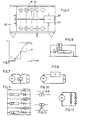
- Figure 1 shows an example of direct coupling of a bulb wind turbine 1 mounted on the support rods 2 made integral with the receiving shaft 3 which is coupled directly to the generator 4 by means of a rigid sleeve 5.
- the shaft 3 is held on the frame 6 by the ball bearing 7.
- a sealed cover 8 protects the generator from the weather.
- the sole 9 is fixed to the top of a post.
- FIG. 2 shows an example of a bulb wind turbine 10 submerged parallel to the water body 11.
- the receiving shaft is placed vertically upwards and coupled to the electric generator 12, made integral with a float 13 by a frame rigid 14 on which is fixed a cowling 15.
- the chassis 14 has the feet 15 provided to prevent the bulbs from rubbing against the bottom of the river during a significant drop in level.
- FIG. 3 schematically represents a bulb wind turbine used in a water mill, whether or not coupled to an electric generator.
- the bulbs are arranged on a plane perpendicular to the water body 16 and driven in rotation by the fig current. by arrow 17.
- Figure 4 there is shown the top view showing 5 rows of bulbs 18 secured to the same receiving shaft 19 coupled to the electric generator 20 fixed on a frame secured to the floats 21,22 which are secured between them and anchored to the ground.
- the bulbs are offset so that there is always at least one that receives the thrust of the water so as to ensure the regularity of the couple.
- Load switching can be carried out electromechanically from a detector of variation of the output voltage across the generator supplying a static or electromechanical electronic programmer relaying the supply of loads.
- FIG. 6 shows an example of an electronic diagram for controlling the progressive variation of the power of a single-phase current generator by phase shift, in which the detector D of variation of the voltage across the terminals of the generator drives a conformator C which transforms the alternating voltage into pulses attacking the "trigger" of the triac T or 2 thyristors.
- a single detector D is enough for a polyphase machine.
- FIG. 7 shows an example of a DC generator diagram in which the progressive variation of the power is obtained by one or more thyristors
- FIG. 8 shows the example of another control diagram of a direct current generator on which the variation of the power is obtained by means of a current chopper H.
- FIG. 9 shows an example of a single-phase alternating current generator diagram with power variation in stages. It comprises, according to the invention, the charges L1, L2, L3, the thresholds of voltage levels S1, S2, S3, defining three power levels and attacking "the trigger" of triacs or thyristors or any other means capable of 'ensure the connection of loads such as for example the static contactor of Figure 10 or that of Figure 11 well known to those skilled in the art. It is also possible to switch on the loads by means of an electromechanical programmer powered by a detector for variation of the output voltage at the terminals of the generator comprising three thresholds defining the power steps.
- FIG. 12 a simplified diagram of a generator is shown, the power of which is adapted by a set of "non-linear" loads constituted for example by a series of silicon diodes whose heat losses constitute the available energy usable by example for heating a heat transfer fluid.
Applications Claiming Priority (2)
| Application Number | Priority Date | Filing Date | Title |
|---|---|---|---|
| FR8011498A FR2483016A1 (fr) | 1980-05-23 | 1980-05-23 | Convertisseur d'energie cinetique de fluides en energie electrique ou mecanique |
| FR8011498 | 1980-05-23 |
Publications (1)
| Publication Number | Publication Date |
|---|---|
| EP0041011A1 true EP0041011A1 (de) | 1981-12-02 |
Family
ID=9242261
Family Applications (1)
| Application Number | Title | Priority Date | Filing Date |
|---|---|---|---|
| EP81400784A Withdrawn EP0041011A1 (de) | 1980-05-23 | 1981-05-19 | Strömungsmaschine zur Erzeugung elektrischer oder mechanischer Energie |
Country Status (2)
| Country | Link |
|---|---|
| EP (1) | EP0041011A1 (de) |
| FR (1) | FR2483016A1 (de) |
Cited By (1)
| Publication number | Priority date | Publication date | Assignee | Title |
|---|---|---|---|---|
| WO2005098233A1 (en) * | 2004-04-08 | 2005-10-20 | Alfred Learmonth | W.w. generator |
Citations (10)
| Publication number | Priority date | Publication date | Assignee | Title |
|---|---|---|---|---|
| BE669697A (de) * | ||||
| US2579311A (en) * | 1948-03-05 | 1951-12-18 | Fairey Charles Richard | Wind-driven power generator |
| FR1460787A (fr) * | 1964-10-16 | 1966-01-07 | Honeywell Inc | Dispositif de transfert d'énergie électrique d'une source à une charge |
| CH437490A (de) * | 1960-12-30 | 1967-06-15 | Bbc Brown Boveri & Cie | Elektrische Anlage mit mindestens einem Stromerzeugungsaggregat, welches eine Turbine und einen Generator mit stark schwankender Drehzahl aufweist |
| FR2266006A2 (de) * | 1973-01-16 | 1975-10-24 | Clausin Jacques | |
| US3942025A (en) * | 1974-04-22 | 1976-03-02 | Zaisui Ri | Process for storing electricity for a fast advancing conveyance and device for storing such electricity |
| DE2446980A1 (de) * | 1974-10-02 | 1976-04-15 | Weineck Albert Hans Joachim | Schwimm-wasserrad als kraftanlage zur stromerzeugung |
| FR2384963A1 (fr) * | 1977-03-25 | 1978-10-20 | Voukourakos Constantin | Anemo-alternateur |
| FR2436890A1 (fr) * | 1978-09-20 | 1980-04-18 | Foa Michel | Eolienne a axe vertical |
| US4200833A (en) * | 1977-10-31 | 1980-04-29 | Wilkerson A W | Power maximization circuit |
-
1980
- 1980-05-23 FR FR8011498A patent/FR2483016A1/fr active Granted
-
1981
- 1981-05-19 EP EP81400784A patent/EP0041011A1/de not_active Withdrawn
Patent Citations (10)
| Publication number | Priority date | Publication date | Assignee | Title |
|---|---|---|---|---|
| BE669697A (de) * | ||||
| US2579311A (en) * | 1948-03-05 | 1951-12-18 | Fairey Charles Richard | Wind-driven power generator |
| CH437490A (de) * | 1960-12-30 | 1967-06-15 | Bbc Brown Boveri & Cie | Elektrische Anlage mit mindestens einem Stromerzeugungsaggregat, welches eine Turbine und einen Generator mit stark schwankender Drehzahl aufweist |
| FR1460787A (fr) * | 1964-10-16 | 1966-01-07 | Honeywell Inc | Dispositif de transfert d'énergie électrique d'une source à une charge |
| FR2266006A2 (de) * | 1973-01-16 | 1975-10-24 | Clausin Jacques | |
| US3942025A (en) * | 1974-04-22 | 1976-03-02 | Zaisui Ri | Process for storing electricity for a fast advancing conveyance and device for storing such electricity |
| DE2446980A1 (de) * | 1974-10-02 | 1976-04-15 | Weineck Albert Hans Joachim | Schwimm-wasserrad als kraftanlage zur stromerzeugung |
| FR2384963A1 (fr) * | 1977-03-25 | 1978-10-20 | Voukourakos Constantin | Anemo-alternateur |
| US4200833A (en) * | 1977-10-31 | 1980-04-29 | Wilkerson A W | Power maximization circuit |
| FR2436890A1 (fr) * | 1978-09-20 | 1980-04-18 | Foa Michel | Eolienne a axe vertical |
Cited By (1)
| Publication number | Priority date | Publication date | Assignee | Title |
|---|---|---|---|---|
| WO2005098233A1 (en) * | 2004-04-08 | 2005-10-20 | Alfred Learmonth | W.w. generator |
Also Published As
| Publication number | Publication date |
|---|---|
| FR2483016B1 (de) | 1984-05-25 |
| FR2483016A1 (fr) | 1981-11-27 |
Similar Documents
| Publication | Publication Date | Title |
|---|---|---|
| EP1362184B1 (de) | Regelungssystem für eine windkraftanlage | |
| FR2478395A1 (fr) | Alternateur electrique adapte a la puissance de la turbine | |
| EP2494184A2 (de) | Starter/generator für einen turbinenmotor sowie steuerungsverfahren dafür | |
| EP2721728A2 (de) | Wechselstromgenerator mit spannungsregelung | |
| EP0783201A1 (de) | Elektromotor des Synchrontyps mit Permanentmagneten und mit einem solchen Motor ausgestattetes Fahrzeug | |
| FR2474781A1 (fr) | Groupe convertisseur comportant un moteur triphase et un generateur synchrone | |
| WO2007042732A1 (fr) | Systeme electromecanique d'entrainement, notamment pour pompe a cavite progressive pour puits de petrole | |
| EP0002981A1 (de) | Verfahren und Einrichtung zur Regelung der Spannung eines elektrischen Generators | |
| EP0041011A1 (de) | Strömungsmaschine zur Erzeugung elektrischer oder mechanischer Energie | |
| CA1246702A (fr) | Rheostat a resistance liquide a circulation d'electrolyte | |
| EP2380261B1 (de) | Selbstgeführter photovoltaischer motor | |
| FR2561718A1 (fr) | Installation hydroelectrique de basse chute | |
| EP0054446B1 (de) | Elektrischer Asynchronmotor, Einrichtung zum Regeln der Speisung eines solchen Motors und Umwälzantrieb mit einem solchen Motor | |
| FR2986917A1 (fr) | Systeme d'alimentation electrique d'une charge, et centrale de production d'energie electrique comprenant un tel systeme | |
| EP0091869B1 (de) | Pumpeneinheit, wie etwa ein Umwälzer für eine zentrale Heizeinrichtung, mit vorbestimmter hydraulischer Kennlinie | |
| FR2517490A1 (fr) | Moteur asynchrone a rotor en court-circuit et a commutation de poles | |
| FR2502420A1 (fr) | Circuit de commande de variation de vitesse de rotation d'un moteur monophase a induction | |
| EP0044244A2 (de) | Einphasiger Asynchronmotor | |
| FR2551142A1 (fr) | Installation de chauffage et/ou de climatisation utilisant l'energie mecanique recueillie sur l'arbre d'une eolienne tournant a une vitesse variable | |
| FR2539564A1 (fr) | Procede et montage pour regler la puissance absorbee par un moteur a courant alternatif | |
| FR2465361A1 (fr) | Circuit d'alimentation controle a courant continu a recuperation | |
| FR2513038A1 (fr) | Dispositif de demarrage d'un moteur asynchrone monophase | |
| FR2478399A1 (fr) | Systeme de commande pour moteurs alternatifs a induction | |
| GB2092237A (en) | Means for Converting Natural Fluid Energy into Electrical or Mechanical Energy | |
| FR2781319A1 (fr) | Regulateur de tension pour un alternateur a aimant permanent |
Legal Events
| Date | Code | Title | Description |
|---|---|---|---|
| PUAI | Public reference made under article 153(3) epc to a published international application that has entered the european phase |
Free format text: ORIGINAL CODE: 0009012 |
|
| AK | Designated contracting states |
Designated state(s): BE CH DE IT NL SE |
|
| 17P | Request for examination filed |
Effective date: 19820524 |
|
| STAA | Information on the status of an ep patent application or granted ep patent |
Free format text: STATUS: THE APPLICATION IS DEEMED TO BE WITHDRAWN |
|
| 18D | Application deemed to be withdrawn |
Effective date: 19830630 |