EP0040994B1 - Transducteur magnétique à entrefer de grande dimension variable pour la lecture ou l'écriture des informations d'un support magnétique - Google Patents
Transducteur magnétique à entrefer de grande dimension variable pour la lecture ou l'écriture des informations d'un support magnétique Download PDFInfo
- Publication number
- EP0040994B1 EP0040994B1 EP81400433A EP81400433A EP0040994B1 EP 0040994 B1 EP0040994 B1 EP 0040994B1 EP 81400433 A EP81400433 A EP 81400433A EP 81400433 A EP81400433 A EP 81400433A EP 0040994 B1 EP0040994 B1 EP 0040994B1
- Authority
- EP
- European Patent Office
- Prior art keywords
- magnetic
- transducer
- air gap
- track
- pole pieces
- Prior art date
- Legal status (The legal status is an assumption and is not a legal conclusion. Google has not performed a legal analysis and makes no representation as to the accuracy of the status listed.)
- Expired
Links
Images


Classifications
-
- G—PHYSICS
- G11—INFORMATION STORAGE
- G11B—INFORMATION STORAGE BASED ON RELATIVE MOVEMENT BETWEEN RECORD CARRIER AND TRANSDUCER
- G11B5/00—Recording by magnetisation or demagnetisation of a record carrier; Reproducing by magnetic means; Record carriers therefor
- G11B5/127—Structure or manufacture of heads, e.g. inductive
- G11B5/187—Structure or manufacture of the surface of the head in physical contact with, or immediately adjacent to the recording medium; Pole pieces; Gap features
- G11B5/245—Structure or manufacture of the surface of the head in physical contact with, or immediately adjacent to the recording medium; Pole pieces; Gap features comprising means for controlling the reluctance of the magnetic circuit in a head with single gap, for co-operation with one track
- G11B5/2452—Structure or manufacture of the surface of the head in physical contact with, or immediately adjacent to the recording medium; Pole pieces; Gap features comprising means for controlling the reluctance of the magnetic circuit in a head with single gap, for co-operation with one track where the dimensions of the effective gap are controlled
-
- G—PHYSICS
- G11—INFORMATION STORAGE
- G11B—INFORMATION STORAGE BASED ON RELATIVE MOVEMENT BETWEEN RECORD CARRIER AND TRANSDUCER
- G11B5/00—Recording by magnetisation or demagnetisation of a record carrier; Reproducing by magnetic means; Record carriers therefor
- G11B5/127—Structure or manufacture of heads, e.g. inductive
- G11B5/31—Structure or manufacture of heads, e.g. inductive using thin films
- G11B5/3109—Details
- G11B5/313—Disposition of layers
- G11B5/3143—Disposition of layers including additional layers for improving the electromagnetic transducing properties of the basic structure, e.g. for flux coupling, guiding or shielding
- G11B5/3146—Disposition of layers including additional layers for improving the electromagnetic transducing properties of the basic structure, e.g. for flux coupling, guiding or shielding magnetic layers
- G11B5/3153—Disposition of layers including additional layers for improving the electromagnetic transducing properties of the basic structure, e.g. for flux coupling, guiding or shielding magnetic layers including at least one magnetic thin film coupled by interfacing to the basic magnetic thin film structure
Definitions
- the present invention relates to magnetic transducers. It is particularly applicable to the reading and writing of information contained on a magnetic recording medium, such as magnetic, rigid or flexible disks and tapes.
- a magnetically anisotropic material has two preferred directions of magnetization (or magnetization) perpendicular to each other. One of them is called “direction of easy magnetization” while the other is called “direction of difficult magnetization”.
- the initial permeability of the material in the direction of difficult magnetization is much higher than the initial permeability of the material in the direction of easy magnetization.
- the magnetic property used to record information on a magnetic support is defined for example either by the absence or the presence of a remanent magnetic induction, or by any variation of the magnetization.
- magnetic disks carry the information on circular concentric recording tracks which have a radial width not exceeding a few hundredths of a millimeter and generally cover most of their two faces.
- the magnetic tapes carry the information on tracks parallel to the length of the tape.
- magnetic transducers The most frequently used means, which make it possible either to record information on media such as discs or tapes, or to read it or finally to carry out one or the other of these two functions, are called " magnetic transducers ". Generally, one or more transducers are associated with a recording medium, the medium moving past it or these. For simplicity, it will be assumed in the following description, that a single transducer is associated with the same support.
- a magnetic transducer comprises a magnetic circuit, around which a winding is arranged, and which comprises an air gap. The latter is disposed at a very small distance from the surface of the support, between zero and a few tenths of a micron.
- the winding comprises the electrical input and / or output wires.
- the winding is supplied with an electric current, the direction or duration of passage of which can be varied.
- the support is thus subjected to the magnetic field of intensity, of variable directions created by the transducer in the immediate vicinity of its air gap (between zero and a few tenths of a micron), which creates on each track of the support a succession of small magnetic domains which have magnetic inductions in opposite directions and whose dimension is linked to the longitudinal recording density (for a magnetic disc, the number of magnetic domains per unit of length measured along the circumference of the track is called longitudinal density). These domains also called “elementary magnetic domains" are distributed over the entire length of the track.
- the latter delivers electrical read signals via its electrical input and / or output wires, signals which are sent to electronic reading circuits associated with the transducers.
- transducers of increasingly smaller dimensions (for example with air gaps whose dimensions are of the order of one to a few tenths of a micron ), such transducers being for example manufactured by the Compagnie Internationale pour l'Informatique CII-Honeywell Bull and described in French patents No. 2,063,693 filed on October 28, 1969 by the Compagnie Internationale pour l'Informatique and the Commissariat à l 'Ener- Atomic engineering under the title: "Integrated magnetic head and process for manufacturing said head” and patent No. 2,209,154 filed on July 3, 1972 by the International Company for Computing under the title: “Advanced magnetic transducers and their process Manufacturing”.
- the magnetic recording medium associated with the transducer travels past it perpendicular to the plane of the pole pieces, perpendicular to the large dimension of the air gap.
- the magnetic material constituting the pole pieces is preferably anisotropic and its axis of difficult magnetization is directed perpendicular to the recording medium.
- each pole piece has a substantially rectangular shape. Its largest dimension is normal to the recording medium. The axis of difficult magnetization of the magnetic material constituting each pole piece is such that it has the same direction as the largest dimension thereof.
- the writing efficiency is defined as the ratio between the magnetic flux created by the transducer in the vicinity of the air gap and the writing current passing through the winding
- the reading efficiency is the ratio between the voltage available across the winding and the magnetic flux entering the transducer at the air gap.
- An integrated transducer described in the aforementioned patent No. 2,297,475, includes pole pieces which have a narrowing at the air gap. The length of the shrinking of the pole pieces in a plane parallel to the recording medium and arranged opposite the latter is equal to the large dimension of the air gap. It is then called "geometric track width LPg ''.
- the pole pieces are machined by ion attack, on a depth of attack equal to Pa (p e is of the order of a few microns) which defines concave lateral surfaces of the pole pieces called S 2 -S 3 , S ' 2 -S' 3 respectively located on either side of the air gap.
- the surface of the pole pieces at the level of the air gap, in the plane of this, of width LP 9 and which is parallel to the recording medium, is designated by S ,.
- L is the width of the pole pieces (small size of these pieces) before machining by ion attack, we generally have L / LPg substantially equal to 2.
- track width LP L reading half the width of the space on either side of the POS position 0 at which the voltage of the signal delivered by the coil is greater than or equal to 5% of A.
- LP L is appreciably greater than LP E : in fact, the signal for reading the information from track P can superimpose another signal, whether track P is isolated or not.
- the fact that the track width read LP is greater than the writing width LP E is essentially due to the following phenomenon: if, during writing, the magnetic flux created by the transducer allowing the writing of information on the support essentially passes through the surface S, (a small part of this flux passes through the concave side surfaces S 2 ⁇ S 3 ⁇ S ' 2 - S' 3 ), on the other hand, when reading the concave side surfaces S 2 and S 3 , S ' 2 and S' 3 capture a large part of the magnetic flux produced by the immediate magnetic environment of track P.
- the main reason for this phenomenon comes from the strong anisotropy of the magnetic material constituting the pole pieces of the transducer.
- the signal delivered by the winding of the transducer coming from the magnetic flux produced by the information of track P is called “useful signal S”
- the signal delivered by the winding coming from the magnetic flux produced by the immediate magnetic environment of the track P is called “spurious signal or noise signal B”.
- the useful signal / S / N noise signal ratio of such a transducer can be considered too low, particularly for certain applications in particular when the number of tracks of the support per unit of length is large (for a magnetic disc this number is called "radial density").
- the first air gap said write air gap, has a large dimension (geometric track width LP) substantially equal to the track width written on the support LP E
- the second air gap said read air gap
- has a large dimension GD L which is lower than LP g and which is such that the entire surface of the air gap and of the pole pieces at the level of this is disposed entirely opposite the track that the read transducer is reading.
- Such a transducer is for example described and claimed in the French patent FR-A. 2,150,335 filed by the Company I.S.M., on August 3, 1972, with a conventional priority date of August 21, 1971.
- This transducer comprises a conductor interposed between two magnetizable elements each forming a pole piece, these two elements forming a magnetizable yoke (which can also be called the main magnetic circuit). These magnetizable elements define a transduction gap adjacent to an edge of the conductor.
- the magnetic yoke has a central part and two marginal parts surrounding said central part. The reluctance of the marginal parts is stronger than the reluctance of the central parts. Therefore, on reading, the participation in the signal of the marginal parts is attenuated to such an extent that the transducer actually reads only on the central part of the air gap.
- the transducer can be written over the entire width of the magnetic yoke (i.e. over the entire width of the pole pieces) using a writing current considerably greater than that which is necessary for the central part to write, a magnetic field of sufficient intensity that can be produced on the marginal parts to saturate the recording medium. Therefore, it is necessary to expend a much greater energy on writing than on reading, and it may result in significant heating of the winding, which is a serious drawback of this transducer.
- Such a transducer makes it possible to solve reading and writing problems for recording densities of the order of 25 tracks per centimeter, the positioning precision A being of the order of a few tens of microns.
- the intervention of the marginal parts of the magnetizable yoke in the reading and writing phenomena takes place in a three-dimensional space.
- the present invention overcomes the drawbacks of both the assembly of two magnetic transducers having air gaps whose large dimensions are parallel and different, than the transducer with a single air gap described in the aforementioned French patent 2,150,335.
- the intervention of the means for differentiating the reading and writing functions takes place in a two-dimensional space, for radial information densities of approximately 240 tracks per centimeter, as it will be specified later on - page 16, line 12.
- FIGS. 1 a, 1 b, 1 c, 2a and 2b the integrated magnetic transducers according to the prior art, illustrated by FIGS. 1 a, 1 b, 1 c, 2a and 2b and secondly on the drawbacks that these present on reading the information illustrated by FIGS. 3a, 3b, 3c and 4.
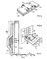
- an integrated magnetic transducer comprises, a magnetic circuit formed by two magnetic polar pieces in thin layers PP 1 and PP 2 entirely superimposed and magnetically coupled to a BOB winding.
- the pole pieces PP 1 and PP 2 are magnetostatically coupled together at a first end EXT and form the air gap G at another end.
- the pole piece PP 1 is deposited on a SUBS substrate made of insulating material as can be seen in FIG. 1c.
- the converter TMA is shown arranged opposite a recording medium SM of which only a part has been shown for simplicity.
- This support comprises a plurality of recording tracks of which only the track P is shown, which comprises a plurality of elementary magnetic domains of which only three are represented, namely the domains A 1 , A 2 and A 3 in FIG. 1 b and five namely, A I to A in Figure 1 c.
- the support SM which scrolls in the direction of the arrow F is for example a magnetic disk belonging to a disk memory.
- disk memories are used more and more in information processing systems because of their storage capacity and the relatively short time taken by the write and / or read transducers to access information contained in any point on the disk from the time they receive from said processing system the order to access this information.
- the pole pieces PP 1 and PP 2 generally consist of a set of several thin magnetic layers and of stacked insulating thin layers, each magnetic layer being separated from the neighboring layer by an insulating layer.
- the assembly thus defined, whether it comprises one or more thin magnetic layers is designated usually under the general name of "magnetic thin films”.
- the BOB winding is formed of a succession of thin conductive and insulating layers stacked in a direction perpendicular to the plane of the magnetic pole pieces PP 1 and PP 2 , a part of the thin conductive and insulating layers flush with the air gap G.
- the insulating layers are arranged between the conductive layers.
- FIG. 1 c only the conductive layers have been shown, namely CO 1 to CO 10 in the embodiment shown in this same figure.
- These conductive layers which have the same shape and are of different dimensions are interconnected by connection conductive elements not shown, for simplicity, in Figures 1a and 1c.
- the BOB winding has a midpoint B, its respective ends being C and A.
- any transducer is selected which it is desired to perform a read operation by sending an electrical selection pulse to its midpoint B.
- the BOB winding comprises three output conductors, namely the conductors C 1 , C 2 , C 3 (FIG. 1b), which are connected to the electronic reading and / or writing circuits of the disc memory containing the disc SM.
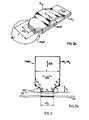
- the integrated magnetic transducers are preferably produced in the manner shown in FIGS. 2a and 2b (see patent No. 2,297,475).
- the pole pieces PP 3 and PP 4 of the latter are made of a magnetically anisotropic material whose axis of difficult magnetization is oriented in the direction DDA perpendicular to the magnetic support SM, which remains tangent to the surface of the pole pieces.
- the axis of easy magnetization of the pole pieces PP 3 and PP 4 is oriented in the direction DFA perpendicular to the direction of difficult magnetization DDA and parallel to the recording medium SM. It is clear that the axis of easy magnetization is also tangent to the surface of the pole pieces PP 3 and PP 4 .
- the TMAP transducer comprises, at its air gap GP, a RET narrowing of the attack depth p a , generally of the order of 5 to 6 microns.
- This narrowing is such that the length of the air gap LPg is substantially less than the width L of the pole pieces outside this narrowing, that is to say the width of the pole pieces before machining.
- the ratio L / LP g is of the order of 2.
- the RET narrowing makes it possible to define the lateral surfaces concave of pole pieces S 2 -S 3 , S ' 2 -S' 3 .
- the surface S 2 (S ' 2 ) is such that the angle it makes with the normal to the support SM is very small while the angle that the surface S 3 (S' 3 ) makes with this same normal with the support is larger and approaches 90 °.
- the writing track width LP E is substantially equal to or slightly greater than the geometric track width LP g of the TMAP transducer (length of the gap G). This is due to a high concentration of the flux lines at the air gap linked to the anisotropy of the pole pieces and therefore to the high magnetic permeability in the DDA direction.
- Figures 3b and 3c provide a better understanding of the definition of track width when reading LP L.
- the signal delivered by the transducer has a maximum voltage A.
- the voltage of the signal delivered by the TMAP transducer is zero and the same is true when the transducer occupies the position POS 2 symmetrical with position POS 1 with respect to position POS o .
- the TMAP transducer occupies a position between the positions ⁇ 1 and ⁇ 2 for which the signal delivered is equal to or greater than 5% of A, it is said by definition that the distance between the positions ⁇ 1 and ⁇ 2 is equal to 2 ⁇ LP L.
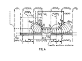
- each of tracks P 1 and P 2 occupies, on average, the positions POSM 1 and POSM 2 distant by a distance DIP. These positions are symbolized by the axes of symmetry of the tracks P 1 and P 2 located in the plane of the figure (axis perpendicular to the surface of the magnetic disc SM). It is further assumed that these axes also represent average positions occupied by the TMAP transducer when the latter performs either read operations or write operations. These axes therefore represent the axes of symmetry of the pole pieces PP 3 and PP 4 of the transducer.
- the DIP distance is slightly greater than the track width when writing LP E.
- the DIP distance is of the order of 40 microns, while the length LP E is of the order of 30 microns.
- the device of the disc memory which contains the magnetic disc SM which makes it possible to position the TMAP transducer opposite tracks P 1 and P 2 (and also of all the other tracks of the disc ) has a perfectly determined positioning precision 8 of the order of a few microns.
- the integrated magnetic transducer TMAP will have a position between a POSLG 1 position called “left limit position” and a POSLD 1 position called “right limit position", these positions POSLG 1 and POSLD 1 being symmetrical with respect to the average position POSM 1 and distant from it by a distance 8. They are also symbolized by broken axes interrupted in FIG. 4.
- the TMAP transducer will occupy a position between the left limit positions and it POSLG 2 and POSLD 2 symmetrical to each other with respect to the average position POSM 2 and distant from it by distance 8. Under these conditions, the left edge of the air gap occupies position LG 2 and the right edge of the air gap position LD 2 . (see figure 4). For the sake of simplicity, it is assumed that the positions of the edge of the air gap LD 1 and LG 2 are practically identical.
- the TAMP transducer carries out the operations for reading the track P 2 while occupying the left limit position POSLG 2 , that is to say the most unfavorable position for the reading of the track P 2 .
- such an ENSLE assembly is composed of a reading transducer TR L whose air gap EN L has a large dimension GD L and of a writing transducer TR E whose air gap EN E has a large dimension LP substantially equal to the track width P written on the magnetic recording medium SM (track width equal to LP E ).
- the air gaps EN E and EN L have the same axis and plane of symmetry perpendicular to their large dimension (and to the plane of Figure 5).
- the S / N ratio can also be improved by using a single transducer having a single air gap as suggested in the aforementioned patent 2,150,335.
- the large dimension of the air gap of the transducer according to the invention then varies according to the function (writing or reading), which it performs.
- the large dimension of the air gap on reading GD L is less than the large dimension GD E that it takes in writing, the latter being such that GD E is greater than GD L and GDE less than GD MAX or GD MAX is a maximum quantity depending on the width of the tracks of the recording medium that we are seeking.
- the transducer includes means for differentiating the reading and writing functions.
- FIG. 6 shows a first embodiment of a transducer TM1 1 , according to the invention having pole pieces PP 5 and PP 6 representing a narrowing RETl 1 , of width GD MAX .
- PE designates the plane parallel to the recording medium SM defined at the level of the narrowing by the faces of the pole pieces PP 5 -PP 6 , arranged opposite the latter.
- the means for differentiating the reading and writing functions of the TMI 1 transducer are constituted by two anisotropic magnetic layers CME 1 and CME 2 deposited on either side of the large dimension GD L of the air gap considered on reading and this on the surface of the pole pieces PP 5 and PP 6 as well as on the surface of the conductors and insulators constituting the air gap ENl 1 of the transducer, surface contained in the plane PE.
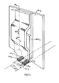
- Figures 7a, 7b and 7c show a second embodiment of TMl 2 more advantageous of an integrated transducer according to the invention.
- the two anisotropic magnetic layers CME 3 and CME 4 arranged on either side of the large dimension GD L of the air gap considered on reading are deposited in hollows CR 1 and CR 2 formed in the pole pieces PP 7 and PP 8 of the transducer (and also in the insulating and conductive layers arranged between these parts at the air gap).
- the surface of the layers CME 3 and CME 4 arranged opposite the magnetic recording medium SM is located in the plane PE (the latter having the same definition as for the transducer TMl 1 ).
- FIGS. 6, 7a and 7c show the directions of easy magnetization DFA and of difficult magnetization DDA of the pole pieces PP 5 and PP 6 on the one hand and PP 7 and PP 8 on the other hand, these being produced from preferably in an anisotropic magnetic material.
- the large dimension of the air gap is equal to GD L which means that the magnetic flux lines emitted by the magnetic information of the track P of the support SM, of width LP E are channeled, at the level of the air gap ENl 2 over a width GD L.
- GD L the magnetic flux lines emitted by the magnetic information of the track P of the support SM, of width LP E are channeled, at the level of the air gap ENl 2 over a width GD L.
- Practically none of the flux lines emitted by the immediate magnetic environment of track P passes through the air gap and enters the winding BOBl 2 of the transducer.
- These last flux lines are channeled by the magnetic layers CME 3 and CME 4 which behave like a magnetic shunt with respect to them.
- the signal / noise ratio S / B of the transducer according to the invention is, on reading greater than that of a transducer according to the prior art such as the TMAP transducer or the TR L transducer of the EMSLE assembly .
- a transducer according to the prior art such as the TMAP transducer or the TR L transducer of the EMSLE assembly .
- the material constituting the layers CME 3 and CME 4 can for example be constituted by iron -nickel Fe-Ni, the thickness of these layers being of the order of 100 nm.
Landscapes
- Engineering & Computer Science (AREA)
- Manufacturing & Machinery (AREA)
- Physics & Mathematics (AREA)
- Electromagnetism (AREA)
- Magnetic Heads (AREA)
Applications Claiming Priority (2)
| Application Number | Priority Date | Filing Date | Title |
|---|---|---|---|
| FR8007453 | 1980-04-02 | ||
| FR8007453A FR2480015A1 (fr) | 1980-04-02 | 1980-04-02 | Transducteur magnetique a entrefer de grande dimension variable pour la lecture et l'ecriture des informations contenues dans un support magnetique |
Publications (2)
| Publication Number | Publication Date |
|---|---|
| EP0040994A1 EP0040994A1 (fr) | 1981-12-02 |
| EP0040994B1 true EP0040994B1 (fr) | 1985-02-13 |
Family
ID=9240464
Family Applications (1)
| Application Number | Title | Priority Date | Filing Date |
|---|---|---|---|
| EP81400433A Expired EP0040994B1 (fr) | 1980-04-02 | 1981-03-20 | Transducteur magnétique à entrefer de grande dimension variable pour la lecture ou l'écriture des informations d'un support magnétique |
Country Status (5)
| Country | Link |
|---|---|
| US (1) | US4386383A (cg-RX-API-DMAC7.html) |
| EP (1) | EP0040994B1 (cg-RX-API-DMAC7.html) |
| JP (1) | JPS56153518A (cg-RX-API-DMAC7.html) |
| DE (1) | DE3168857D1 (cg-RX-API-DMAC7.html) |
| FR (1) | FR2480015A1 (cg-RX-API-DMAC7.html) |
Families Citing this family (10)
| Publication number | Priority date | Publication date | Assignee | Title |
|---|---|---|---|---|
| JPS57123516A (en) * | 1981-01-23 | 1982-08-02 | Matsushita Electric Ind Co Ltd | Thin-film magnetic head |
| JPS5819717A (ja) * | 1981-07-30 | 1983-02-04 | Fujitsu Ltd | 垂直磁化記録再生用ヘッド |
| US4935832A (en) * | 1987-04-01 | 1990-06-19 | Digital Equipment Corporation | Recording heads with side shields |
| US5170303A (en) * | 1990-04-30 | 1992-12-08 | Seagate Technology Inc. | Inductive thin film head having improved readback characteristics |
| JP2683503B2 (ja) * | 1993-09-02 | 1997-12-03 | インターナショナル・ビジネス・マシーンズ・コーポレイション | 磁性膜構造 |
| JPH09293209A (ja) * | 1996-04-26 | 1997-11-11 | Fujitsu Ltd | 薄膜磁気ヘッド、磁気記録装置及び薄膜磁気ヘッドの製造方法 |
| US5940250A (en) * | 1997-10-21 | 1999-08-17 | Maxtor Corporation | Disk drive head having a read wide/write narrow architecture |
| US6765756B1 (en) | 1999-03-12 | 2004-07-20 | Western Digital (Fremont), Inc. | Ultra-short yoke and ultra-low stack height writer and method of fabrication |
| US6865056B1 (en) * | 1999-10-05 | 2005-03-08 | Seagate Technology Llc | Longitudinal magnetic recording heads with variable-length gaps |
| US6510022B1 (en) * | 2000-02-15 | 2003-01-21 | International Business Machines Corporation | Method for shaping pole pieces of magnetic heads by chemical mechanical polishing |
Family Cites Families (6)
| Publication number | Priority date | Publication date | Assignee | Title |
|---|---|---|---|---|
| GB746537A (en) | 1953-03-04 | 1956-03-14 | Clevite Corp | Improvements in or relating to magnetic transducer heads |
| US3353168A (en) * | 1964-04-09 | 1967-11-14 | Potter Instrument Co Inc | Wide-record narrow-read magnetic head |
| BE758053A (fr) * | 1969-10-28 | 1971-04-01 | Commissariat Energie Atomique | Tete magnetique integree et procede de fabrication de ladite tete |
| GB1344890A (en) * | 1971-08-21 | 1974-01-23 | Ibm | Electromagnetic transducers |
| GB1357400A (en) | 1971-11-03 | 1974-06-19 | Ibm | Magnetic recording and reproducing apparatus |
| FR2297475A1 (fr) * | 1975-01-10 | 1976-08-06 | Cii | Perfectionnements exportes aux structures de tetes magnetiques du type dit " integre " |
-
1980
- 1980-04-02 FR FR8007453A patent/FR2480015A1/fr active Granted
-
1981
- 1981-03-12 US US06/242,924 patent/US4386383A/en not_active Expired - Fee Related
- 1981-03-20 EP EP81400433A patent/EP0040994B1/fr not_active Expired
- 1981-03-20 DE DE8181400433T patent/DE3168857D1/de not_active Expired
- 1981-04-02 JP JP4852681A patent/JPS56153518A/ja active Pending
Also Published As
| Publication number | Publication date |
|---|---|
| FR2480015B1 (cg-RX-API-DMAC7.html) | 1984-09-21 |
| JPS56153518A (en) | 1981-11-27 |
| EP0040994A1 (fr) | 1981-12-02 |
| US4386383A (en) | 1983-05-31 |
| DE3168857D1 (en) | 1985-03-28 |
| FR2480015A1 (fr) | 1981-10-09 |
Similar Documents
| Publication | Publication Date | Title |
|---|---|---|
| EP0107589B1 (fr) | Dispositif d'écriture d'informations sur un support magnétique | |
| EP0046697B1 (fr) | Transducteur magnétique intégré | |
| EP0284495B1 (fr) | Tête magnétique de lecture pour piste de très faible largeur et procédé de fabrication | |
| EP0677838A2 (fr) | Dispositif matriciel à têtes magnétiques notamment en couches minces | |
| FR2630244A1 (fr) | Dispositif d'ecriture et de lecture sur un support magnetique et son procede de fabrication | |
| FR2575577A1 (fr) | Transducteur magnetique d'ecriture/lecture pour enregistrement perpendiculaire | |
| EP0040994B1 (fr) | Transducteur magnétique à entrefer de grande dimension variable pour la lecture ou l'écriture des informations d'un support magnétique | |
| EP0035943B1 (fr) | Tête magnétique d'enregistrement et de lecture de données magnétiques à largeur de piste variable | |
| EP0061363B1 (fr) | Transducteur magnétorésistant de lecture d'informations à très haute densité | |
| EP0452193B1 (fr) | Procédés de réalisation d'une tête magnétique d'enregistrement/lecture | |
| FR2658647A1 (fr) | Tete magnetique horizontale a effet hall et son procede de realisation. | |
| EP0041409A1 (fr) | Transducteur magnétique pour la lecture ou l'écriture des informations d'un support magnétique | |
| EP0624871A2 (fr) | Tête magnétique d'écriture pour enregistrement magnéto-optique | |
| EP0369839A1 (fr) | Tête magnétique à entrefer saturable et dispositif matriciel comportant un ensemble de telles têtes | |
| EP0028177B1 (fr) | Transducteur magnétique intégré | |
| EP0188943B1 (fr) | Transducteur magnétique d'écriture pour enregistrement transversal | |
| EP0132186B1 (fr) | Transducteur magnétique hautement intégré d'écriture d'informations sur un support magnétique | |
| FR2494952A1 (fr) | Transducteur magnetoresistant de lecture d'un support d'enregistrement a haute densite d'informations | |
| EP2355098B1 (fr) | Dispositif de lecture magnétique | |
| EP0409673B1 (fr) | Tête magnétique intégrée d'enregistrement | |
| EP0644528A1 (fr) | Tête magnétique de lecture et d'écriture à élément magnétorésistant compensé en écriture | |
| EP1107236A1 (fr) | Tête de lecture planaire à élément magnéto-résistif | |
| FR2510289A1 (fr) | Dispositif d'enregistrement lecture d'un support d'informations | |
| FR2797709A1 (fr) | Tete de lecteur magneto-optique a faible bruit et grande efficacite |
Legal Events
| Date | Code | Title | Description |
|---|---|---|---|
| PUAI | Public reference made under article 153(3) epc to a published international application that has entered the european phase |
Free format text: ORIGINAL CODE: 0009012 |
|
| AK | Designated contracting states |
Designated state(s): DE GB IT |
|
| 17P | Request for examination filed |
Effective date: 19811116 |
|
| ITF | It: translation for a ep patent filed | ||
| GRAA | (expected) grant |
Free format text: ORIGINAL CODE: 0009210 |
|
| AK | Designated contracting states |
Designated state(s): DE GB IT |
|
| REF | Corresponds to: |
Ref document number: 3168857 Country of ref document: DE Date of ref document: 19850328 |
|
| PLBE | No opposition filed within time limit |
Free format text: ORIGINAL CODE: 0009261 |
|
| STAA | Information on the status of an ep patent application or granted ep patent |
Free format text: STATUS: NO OPPOSITION FILED WITHIN TIME LIMIT |
|
| 26N | No opposition filed | ||
| ITTA | It: last paid annual fee | ||
| PGFP | Annual fee paid to national office [announced via postgrant information from national office to epo] |
Ref country code: GB Payment date: 19890331 Year of fee payment: 9 |
|
| PGFP | Annual fee paid to national office [announced via postgrant information from national office to epo] |
Ref country code: DE Payment date: 19890407 Year of fee payment: 9 |
|
| PG25 | Lapsed in a contracting state [announced via postgrant information from national office to epo] |
Ref country code: GB Effective date: 19900320 |
|
| GBPC | Gb: european patent ceased through non-payment of renewal fee | ||
| PG25 | Lapsed in a contracting state [announced via postgrant information from national office to epo] |
Ref country code: DE Effective date: 19901201 |