EP0040897A1 - Process for electrode fabrication having a uniformly distributed catalyst layer upon a porous substrate - Google Patents
Process for electrode fabrication having a uniformly distributed catalyst layer upon a porous substrate Download PDFInfo
- Publication number
- EP0040897A1 EP0040897A1 EP81300306A EP81300306A EP0040897A1 EP 0040897 A1 EP0040897 A1 EP 0040897A1 EP 81300306 A EP81300306 A EP 81300306A EP 81300306 A EP81300306 A EP 81300306A EP 0040897 A1 EP0040897 A1 EP 0040897A1
- Authority
- EP
- European Patent Office
- Prior art keywords
- substrate
- sulfur dioxide
- solution
- electrode
- palladium
- Prior art date
- Legal status (The legal status is an assumption and is not a legal conclusion. Google has not performed a legal analysis and makes no representation as to the accuracy of the status listed.)
- Ceased
Links
Images


Classifications
-
- C—CHEMISTRY; METALLURGY
- C25—ELECTROLYTIC OR ELECTROPHORETIC PROCESSES; APPARATUS THEREFOR
- C25B—ELECTROLYTIC OR ELECTROPHORETIC PROCESSES FOR THE PRODUCTION OF COMPOUNDS OR NON-METALS; APPARATUS THEREFOR
- C25B11/00—Electrodes; Manufacture thereof not otherwise provided for
- C25B11/04—Electrodes; Manufacture thereof not otherwise provided for characterised by the material
- C25B11/042—Electrodes formed of a single material
- C25B11/043—Carbon, e.g. diamond or graphene
- C25B11/044—Impregnation of carbon
Definitions
- This invention relates to a process for preparing electrodes for the anodic oxidation of sulfur dioxide and of the type in which and a platinum group metal- containing catalyst solution is coated onto a high-surface-area porous substrate and dried thus forming a -film on the substrate surface.
- the present invention resides in a process for preparing electrodes for the anodic oxidation of sulfur dioxide and of the type in which a platinum group metal containing catalyst solution is coated onto a high-surface-area porous substrate and dried, thus forming a film on the substrate surface, characterized by:
- a pressure differential of 100-100 milli-meters of. mercury is applied across the substrate and the latter is radiantly heated.
- the sulfur cycle hydrogen generation system of Fig. 1 is a typical use of the sulfur dioxide oxidation electrode of this invention.
- an electrolyzer 1 contains an aqueous solution of sulfuric acid 2 which is saturated with 50 2 .
- Direct current is applied to the solution through an anode 3 (made by the process described herein) and a cathode 4.
- Sulfuric acid and hydrogen gas are generated at the anode 3 and the cathode 4, respectively.
- Inlets 5 and 6 are provided for the addition of more dilute sulfuric acid and additional sulfur dioxide.
- the hydrogen product leaves by outlet 7 where it separates from the sulfuric acid. Unconsumed sulfur dioxide leaves by outlet 8 with the more concentrated sulfuric acid solution, and both are recycled.
- a portion of the sulfuric acid from outlet 8 passes to vaporizer 9 where water is evaporated and its concentration is increased.
- the concentrated sulfuric acid then passes to oxygen generator 10 where the sulfuric acid is heated over a catalyst, for example, of platinum or vanadium pentoxide, to decompose it into water, sulfur dioxide, and oxygen which pass to oxygen recovery unit 11.
- a catalyst for example, of platinum or vanadium pentoxide
- oxygen recovery unit 11 the sulfur dioxide is separated from the oxygen by lowering the temperature to condense the sulfur dioxide into a liquid.
- the sulfur dioxide and the water are then returned to inlet 6 of the electrolytic cell 1, thus completing the cycle.
- a hydrogen-ion-permeable membrane 12 separates the fluid around the anode 3 from the fluid around the cathode 4.
- Fig. 6 The appearance and microstructures of a typical carbon (plate) substrate are illustrated in Fig. 6. These inexpensive carbon substrates provide good porosity, electrical conductivity and mechanical strength. While anodes of carbon (graphite) catalyzed with fine platinum particles -have been used for preparation of sulfuric acid from sulfur dioxide, commercially available platinum-coated carbon electrodes have been found to have an extremely non-uniform coating of platinum. All such electrodes had, as shown in Fig. 5, areas which were clearly uncoated.
- a five by five centimeter porous carbon substrate (mean pore size approximately nine microns) was activated by oxidation in a concentrated nitric acid (13.5 normal at 80°C) .
- the oxidized carbon substrate 13 was mounted (as shown in Fig. 3) in a lucite holder 14 using a seal around the perimeter of the substrate. The substrate was then positioned in a horizontal plane with its underside exposed to a cavity 18 that was connected to a vacuum pump.
- the palladium-covered carbon substrate prepared as above is further treated, for example, at a temperature of 400-500°C in a stream of helium gas containing 5% oxygen.
- Fig. 4 also illustrates the use of a positive pressure cavity 22 (as opposed to the vacuum cavity of Fig. 3) as a means for applying the pressure differential across the substrate 13.
- a positive pressure cavity 22 as opposed to the vacuum cavity of Fig. 3
- the pressure could be applied by a pump directly to the coating solution (thus the pressure chamber 22 would be completely filled with fluid) or by using sufficient depth of solution to provide the pressure hydrostatically. Neither of these techniques, however, lend themselves to radiant heating from the side to which the solution is applied and thus the arrangement of Fig. 3 is preferred.
- the differential pressure should be less than about 100 millimeters of mercury if carbon substrates are used to avoid damage to the substrate.
- a differential pressure of 10-30 millimeters of mercury is used with carbon substrates.
- Other types of substrates e.g. a sub-. strate sintered from finely divided titanium powder
- the upper limit of the pressure differential is determined by the strength of the substrate.
- the palladium or palladium oxide catalyst is preferred (although other platinum group of metals can also be uniformly deposited by the techniques described herein) and palladium is preferably deposited using radiant heating to 40-60°C.
Abstract
Process for preparing electrodes for the oxidation of sulfur dioxide (including the oxidation of sulfur dioxide in a sulfur cycle process for hydrogen generation) in which a platinum group metal containing catalyst material is coated evenly onto a high-surface-area porous substrate. A solution is applied onto the substrate by a vacuum filtration method. A pressure differential of at least 10 mm-Hg is applied across the substrate. The substrate is uniformly heated (preferably by radiant heating).
Description
- This invention relates to a process for preparing electrodes for the anodic oxidation of sulfur dioxide and of the type in which and a platinum group metal- containing catalyst solution is coated onto a high-surface-area porous substrate and dried thus forming a -film on the substrate surface.
- Of all of the advanced concepts proposed for the large scale production of hydrogen, the process described in U.S. Patent 3,888,750 (Brecher and Wu), appears to be the most economical. That process is a two-step cycle which decomposes water with the hydrogen being generated in an electrolyzer and the oxygen being generated in a separate step in a thermochemical apparatus. Sulfur dioxide is electrochemically oxidized at a relatively low temperature (less than about 150°C) to produce sulfuric acid on the anode while hydrogen gas is simultaneously generated on the cathode. The sulfuric acid is then catalytically reduced at higher temperatures (generally above 870°C) into sulfur dioxide and oxygen. Subsequently, the sulfur dioxide is recycled as a reactant in the first step. The use of sulfur dioxide as an anode depo- larizer reduces the thermo-dynamic reversible voltage of an electrolyzer from 1.23 volts (for the conventional electrolysis of water) to only 0.17 volts.
- While the sulfur cycle reduces the electric power required in electrolysis, it has been found that conventional electrode coating processes have not resulted in uniform coatings of a catalyst on the porous substrates. Such non-uniformity has resulted in increased electrode voltage at a given production rate and thus a loss of efficiency.
- Accordingly the present invention resides in a process for preparing electrodes for the anodic oxidation of sulfur dioxide and of the type in which a platinum group metal containing catalyst solution is coated onto a high-surface-area porous substrate and dried, thus forming a film on the substrate surface, characterized by:
- a) applying a solution containing at least one platinum group metal to a first side of said substrate;
- b) applying a pressure differential of at least 10 mm-Hg across said substrate with said first side of said substrate being the higher pressure side; and
- c) uniformly heating at least one side of said substrate.
- Desirably, a pressure differential of 100-100 milli-meters of. mercury is applied across the substrate and the latter is radiantly heated.
- In order that the invention can be more clearly understood, convenient embodiments thereof will now be described, by way of example, with reference to the accompanying drawings in which:
- Figure 1 shows a block diagram illustrating the sulfur cycle hydrogen generation system in which the electrode made by the process of this invention can be used;
- Fig. 2 is a diagram of an electrolytic cell (electrolyzer) in which the electrode fabricated by this process can be used;
- Fig. 3 is a cross-section of a substrate holder and substrate in which a vacuum is used to produce the pressure differential;
- Fig. 4 is a cross-section of a substrate holder and substrate where positive pressure is used to produce the pressure differential;
- Fig. 5 shows the appearance of a commercially available platinum-coated carbon electrode;
- Fig. 6A shows the general appearance and Figure 6B shows a scanning electron micrograph of a typical carbon substrate prior to coating by the method of this invention; and
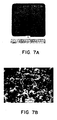
- Fig. 7A illustrates the general appearance and Figure 6B shows a scanning electron micrograph of a resulting electrode prepared by the process of this invention.
- The sulfur cycle hydrogen generation system of Fig. 1 is a typical use of the sulfur dioxide oxidation electrode of this invention. In Figs. 1 and 2, an electrolyzer 1 contains an aqueous solution of sulfuric acid 2 which is saturated with 502. Direct current is applied to the solution through an anode 3 (made by the process described herein) and a
cathode 4. Sulfuric acid and hydrogen gas are generated at the anode 3 and thecathode 4, respectively. Inlets 5 and 6 are provided for the addition of more dilute sulfuric acid and additional sulfur dioxide. The hydrogen product leaves by outlet 7 where it separates from the sulfuric acid. Unconsumed sulfur dioxide leaves by outlet 8 with the more concentrated sulfuric acid solution, and both are recycled. A portion of the sulfuric acid from outlet 8 passes to vaporizer 9 where water is evaporated and its concentration is increased. The concentrated sulfuric acid then passes tooxygen generator 10 where the sulfuric acid is heated over a catalyst, for example, of platinum or vanadium pentoxide, to decompose it into water, sulfur dioxide, and oxygen which pass to oxygen recovery unit 11. In oxygen recovery unit 11, the sulfur dioxide is separated from the oxygen by lowering the temperature to condense the sulfur dioxide into a liquid. The sulfur dioxide and the water are then returned to inlet 6 of the electrolytic cell 1, thus completing the cycle. A hydrogen-ion-permeable membrane 12 separates the fluid around the anode 3 from the fluid around thecathode 4. - Cyclic voltammetric studies have revealed that the anodic oxidation of sulfur dioxide is highly irreversible. The overvoltage on the anode contributes a significant proportion to the overall potential of an electrolyzer, and thus is one of the major sources of efficiency loss in the cell. Methods to reduce the anode overvoltage include the use of appropriate electrode catalyst and the maximization of active surface areas of the electrode. To maximize the surface area, are electro-catalysts supported on highly porous substrates (electrodes made completely of a palladium, for example, rather than as a palladium coating on a substrate would, of course, be extremely expensive). Carbon substrates formed from extremely fine carbon powder provides a porous substrate with a very high'. surface area (a specific surface area of at least 200 and typically about 450 square meters per gram). The appearance and microstructures of a typical carbon (plate) substrate are illustrated in Fig. 6. These inexpensive carbon substrates provide good porosity, electrical conductivity and mechanical strength. While anodes of carbon (graphite) catalyzed with fine platinum particles -have been used for preparation of sulfuric acid from sulfur dioxide, commercially available platinum-coated carbon electrodes have been found to have an extremely non-uniform coating of platinum. All such electrodes had, as shown in Fig. 5, areas which were clearly uncoated.
- Early experiments to improve the uniformity of catalyzed carbon plate electrodes which, like the commercially available electrodes, when visually inspected, had little or no catalyst in the center. When these electrodes were disected, there was also little or no catalysts on interior surfaces. In this early work, the aqueous solution of noble metal compound (such as dihydro- 'gen hexachloroplatinate or palladium acetate) was applied to the surface of a porous carbon substrate by painting. The substrate doped with catalyst was slowly dried in a furnace at about 50°C. The resultant non-uniform coatings may have been caused by the pressure of the water vapor in the pores increasing during the evaporation process and gradually repealing the solution out of the pores (the aqueous solution also apparently migrated toward low temperature regions at the edges).
- In order to avoid the problems of those early techniques, a new method was developed in which.a pressure differential across the substrate was used to push solution through the substrate and radiant heating of one side of the substrate was used to heat the substrate uniformly (note that uniformity on the surface and on planes parallel to the surface is a critical but that temperature differences through the thickness of the material - e.g. between planes parallel to the surface - can be tolerated).
- The invention will now be illustrated with reference to the following Example:
- A, A five by five centimeter porous carbon substrate (mean pore size approximately nine microns) was activated by oxidation in a concentrated nitric acid (13.5 normal at 80°C) .
- B. 0.255 grams of palladium acetate was dissolved in 30 milliliter of distilled water and the solution was then heated at 80°C for 30 minutes.
- C. The oxidized
carbon substrate 13 was mounted (as shown in Fig. 3) in a lucite holder 14 using a seal around the perimeter of the substrate. The substrate was then positioned in a horizontal plane with its underside exposed to acavity 18 that was connected to a vacuum pump. - D. A small amount of solution was poured onto the upper side of the substrate and the vacuum was applied to maintain a pressure differential of approximately 10 millimeters of mercury across the
substrate 13. Thesubstrate 13 was heated in situ to 40-60°C using an overhead infrared lamp 20 (palladium acetate was thus uniformly deposited over theelectrode 13 as the solution filtered through the pores). This treatment (adding solution, applying pressure differential, and reheating) can be repeated to increase the thickness of compound applied. - E. After the deposition of palladium acetate was completed, the thermal decomposition process was performed in a nitrogen or hydrogen atmosphere at 600°C for 2 hours, which resulted in the formation of a thin layer of palladium completely covering the electrode surface (as shown in Fig. 7, the density of palladium particles is high and the distribution is uniform).
- When a palladium-oxide electrode is to be used, the palladium-covered carbon substrate prepared as above is further treated, for example, at a temperature of 400-500°C in a stream of helium gas containing 5% oxygen.
- While the electrode is preferably heated from above (as apparently the solution being applied tends to migrate towards lower temperature regions), the substrate could be heated from below, as shown in Fig. 4. Fig. 4 also illustrates the use of a positive pressure cavity 22 (as opposed to the vacuum cavity of Fig. 3) as a means for applying the pressure differential across the
substrate 13. Whether heated from above as in Fig. 3, or below as in Fig. 4 (or both as can be done by sticking a radiant heating source in either thevacuum cavity 18 of Fig. 3 or thepressure cavity 22 of Fig. 4) or whether the pressure differential is applied by a positive pressure or by a vacuum (or both), it is critical that one uses a pressure differential to uniformly move the solution through the substrate. - Experiments in which uniform heating alone was used (a variation of the above process without a pressure differential), failed to produce uniform coatings. When a pressure differential was used with non-uniform heating, poor results were obtained. Only by using both the uniform heating and the pressure differential were even coatings obtained. Although uniform heating in an oven was accomplished experimentally, oven heating tended to be non-uniform unless extreme care was taken and radiant heating is preferred.
- Again with reference to Fig. 4, it should be noted that the pressure could be applied by a pump directly to the coating solution (thus the
pressure chamber 22 would be completely filled with fluid) or by using sufficient depth of solution to provide the pressure hydrostatically. Neither of these techniques, however, lend themselves to radiant heating from the side to which the solution is applied and thus the arrangement of Fig. 3 is preferred. - It has been found that at least ten millimeter of mercury's differential pressure is required to move the fluid through the substrate at a practical rate and that the differential pressure should be less than about 100 millimeters of mercury if carbon substrates are used to avoid damage to the substrate. Preferably a differential pressure of 10-30 millimeters of mercury is used with carbon substrates. Other types of substrates (e.g. a sub-. strate sintered from finely divided titanium powder) can also be used and the upper limit of the pressure differential is determined by the strength of the substrate. As . described in the aforementioned copending application, the palladium or palladium oxide catalyst is preferred (although other platinum group of metals can also be uniformly deposited by the techniques described herein) and palladium is preferably deposited using radiant heating to 40-60°C.
- In U.S. Patent Application S.N. 084,494 entitled "Palladium Electrode For Use In Sulfur Cycle Hydrogen Operation Process", filed October 15, 1979, there is described a palladium electrode for use in the anodic oxidation of sulfur dioxide. The use of a palladium catalyst rather than the platinum provides for a significant voltage reduction and therefore a greatly increased electrolyzer efficiency. The process of the present invention can be used to fabricate the palladium electrode of this copending application.
Claims (5)
1. A process for preparing electrodes for the anodic oxidation of sulfur dioxide, and of the type in which a platinum group metal containing catalyst solution is coated onto a high-surface-area porous substrate and dried, thus forming a film on the substrate surface, characterized by:
a) applying a solution containing at least one platinum group metal to a first side of said substrate;
b) applying a pressure differential of at least 10 mm-Hg across said substrate with said first side of said substrate being the higher pressure side; and
c) uniformly heating at least one side of said substrate.
2. A process according to claim 1, characterized in that the differential pressure across the substrate is 10-100 mm-Hg.
3. A process according to claim 2, characterized in that the differential pressure is 10-30 mm-Hg.
4. A process according to claim 3., characterized in that the substrate is radiantly heated.
5. A process according to claim 4, characterized in that the platinum group metal is palladium and the substrate is radiantly heated to 40-60°C.
Applications Claiming Priority (2)
| Application Number | Priority Date | Filing Date | Title |
|---|---|---|---|
| US15311080A | 1980-05-23 | 1980-05-23 | |
| US153110 | 1980-05-23 |
Publications (1)
| Publication Number | Publication Date |
|---|---|
| EP0040897A1 true EP0040897A1 (en) | 1981-12-02 |
Family
ID=22545807
Family Applications (1)
| Application Number | Title | Priority Date | Filing Date |
|---|---|---|---|
| EP81300306A Ceased EP0040897A1 (en) | 1980-05-23 | 1981-01-23 | Process for electrode fabrication having a uniformly distributed catalyst layer upon a porous substrate |
Country Status (7)
| Country | Link |
|---|---|
| EP (1) | EP0040897A1 (en) |
| JP (1) | JPS579889A (en) |
| AU (1) | AU6609981A (en) |
| BR (1) | BR8100253A (en) |
| CA (1) | CA1150231A (en) |
| ES (1) | ES8300878A1 (en) |
| ZA (1) | ZA81173B (en) |
Cited By (5)
| Publication number | Priority date | Publication date | Assignee | Title |
|---|---|---|---|---|
| EP0066349A1 (en) * | 1981-06-01 | 1982-12-08 | Westinghouse Electric Corporation | Carbon cloth supported electrode |
| EP0092603A1 (en) * | 1982-04-15 | 1983-11-02 | Westinghouse Electric Corporation | Method of making electrodes |
| EP0683247A1 (en) * | 1994-05-20 | 1995-11-22 | Bayer Ag | Process for manufacturing stable graphite cathodes for the electrolysis of chlorhydric acid |
| GB2365023A (en) * | 2000-07-18 | 2002-02-13 | Ionex Ltd | Increasing the surface area of an electrode |
| US7238841B2 (en) | 1997-02-28 | 2007-07-03 | E. I. Du Pont De Nemours And Company | Polymer-supported phosphorus ligands for catalysts |
Citations (4)
| Publication number | Priority date | Publication date | Assignee | Title |
|---|---|---|---|---|
| GB1329153A (en) * | 1970-01-09 | 1973-09-05 | Solvay | Electrodes for electrochemical processes |
| DE2002298B2 (en) * | 1970-01-20 | 1973-10-11 | Guenter Dipl.-Chem. 4134 Rheinberg Barthel | Process for the production of electrodes for technical water electrolysis |
| US3778307A (en) * | 1967-02-10 | 1973-12-11 | Chemnor Corp | Electrode and coating therefor |
| US4164457A (en) * | 1977-06-23 | 1979-08-14 | Kernforschungsanlage Julich Gesellschaft Mit Beschrankter Haftung | Method of recovering hydrogen and oxygen from water |
-
1981
- 1981-01-09 AU AU66099/81A patent/AU6609981A/en not_active Abandoned
- 1981-01-12 ZA ZA00810173A patent/ZA81173B/en unknown
- 1981-01-13 CA CA000368368A patent/CA1150231A/en not_active Expired
- 1981-01-16 BR BR8100253A patent/BR8100253A/en unknown
- 1981-01-23 JP JP809781A patent/JPS579889A/en active Pending
- 1981-01-23 EP EP81300306A patent/EP0040897A1/en not_active Ceased
- 1981-05-22 ES ES502417A patent/ES8300878A1/en not_active Expired
Patent Citations (4)
| Publication number | Priority date | Publication date | Assignee | Title |
|---|---|---|---|---|
| US3778307A (en) * | 1967-02-10 | 1973-12-11 | Chemnor Corp | Electrode and coating therefor |
| GB1329153A (en) * | 1970-01-09 | 1973-09-05 | Solvay | Electrodes for electrochemical processes |
| DE2002298B2 (en) * | 1970-01-20 | 1973-10-11 | Guenter Dipl.-Chem. 4134 Rheinberg Barthel | Process for the production of electrodes for technical water electrolysis |
| US4164457A (en) * | 1977-06-23 | 1979-08-14 | Kernforschungsanlage Julich Gesellschaft Mit Beschrankter Haftung | Method of recovering hydrogen and oxygen from water |
Cited By (8)
| Publication number | Priority date | Publication date | Assignee | Title |
|---|---|---|---|---|
| EP0066349A1 (en) * | 1981-06-01 | 1982-12-08 | Westinghouse Electric Corporation | Carbon cloth supported electrode |
| EP0092603A1 (en) * | 1982-04-15 | 1983-11-02 | Westinghouse Electric Corporation | Method of making electrodes |
| EP0683247A1 (en) * | 1994-05-20 | 1995-11-22 | Bayer Ag | Process for manufacturing stable graphite cathodes for the electrolysis of chlorhydric acid |
| US5575985A (en) * | 1994-05-20 | 1996-11-19 | Bayer Aktiengesellschaft | Preparation of stable graphite |
| CN1052038C (en) * | 1994-05-20 | 2000-05-03 | 拜尔公司 | Preparation of stable graphite cathodes for the electrolysis of hydrochloric acid |
| US7238841B2 (en) | 1997-02-28 | 2007-07-03 | E. I. Du Pont De Nemours And Company | Polymer-supported phosphorus ligands for catalysts |
| GB2365023A (en) * | 2000-07-18 | 2002-02-13 | Ionex Ltd | Increasing the surface area of an electrode |
| GB2365023B (en) * | 2000-07-18 | 2002-08-21 | Ionex Ltd | A process for improving an electrode |
Also Published As
| Publication number | Publication date |
|---|---|
| ZA81173B (en) | 1982-04-28 |
| JPS579889A (en) | 1982-01-19 |
| ES502417A0 (en) | 1982-11-01 |
| ES8300878A1 (en) | 1982-11-01 |
| AU6609981A (en) | 1981-11-26 |
| BR8100253A (en) | 1982-01-12 |
| CA1150231A (en) | 1983-07-19 |
Similar Documents
| Publication | Publication Date | Title |
|---|---|---|
| Devilliers et al. | Cr (III) oxidation with lead dioxide-based anodes | |
| Grubb et al. | Batteries with solid ion‐exchange membrane electrolytes: II. Low‐temperature hydrogen‐oxygen fuel cells | |
| US4498942A (en) | Electrolysis apparatus using a diaphragm of a solid polymer electrolyte, and method for production thereof | |
| US4414092A (en) | Sandwich-type electrode | |
| US5516972A (en) | Mediated electrochemical oxidation of organic wastes without electrode separators | |
| Watanabe et al. | Electrocatalysis by ad-atoms: Part XXIII. Design of platinum ad-electrodes for formic acid fuel cells with ad-atoms of the IVth and the Vth groups | |
| WO1996005336A1 (en) | Electrochemical device for removal and regeneration of oxygen and method | |
| US5407550A (en) | Electrode structure for ozone production and process for producing the same | |
| JP2003051322A (en) | Manufacturing method of functional ceramic layer | |
| US20030047459A1 (en) | Electrochemical reacting electrode, method of making, and application device | |
| US4142949A (en) | Process for producing an electrode for use in the electrolytic generation of hydrogen peroxide | |
| EP0560740B1 (en) | Apparatus and process for electrolytic ozone generation | |
| US5676808A (en) | Electrolytic cell using gas diffusion electrode | |
| Doblhofer et al. | Polymer‐Metal Composite Thin Films on Electrodes | |
| EP0040897A1 (en) | Process for electrode fabrication having a uniformly distributed catalyst layer upon a porous substrate | |
| US3222265A (en) | Electrolysis method and apparatus employing a novel diaphragm | |
| CN113061926A (en) | Titanium dioxide anode diffusion layer for PEM water electrolysis cell and preparation method and application thereof | |
| JPH06330367A (en) | Production of gas electrode | |
| JP3943151B2 (en) | Electrode for electrochemical process and method of using the electrode | |
| US3196050A (en) | Method of preparing a catalyst impregnated carbon electrode | |
| KR860700273A (en) | Complex Catalytic Substance for Electrolytic Electrode and Method of Manufacturing the Same | |
| EP0036709B1 (en) | Process for manufacturing a polychelate coating and electrode coated therewith | |
| US6165333A (en) | Cathode assembly and method of reactivation | |
| RU2749729C1 (en) | Method for production of multilayer metal nanostructured catalytic coatings | |
| SU899719A1 (en) | Electrode for electrochemical processing and process for making the same |
Legal Events
| Date | Code | Title | Description |
|---|---|---|---|
| PUAI | Public reference made under article 153(3) epc to a published international application that has entered the european phase |
Free format text: ORIGINAL CODE: 0009012 |
|
| AK | Designated contracting states |
Designated state(s): BE CH DE FR GB IT LI NL SE |
|
| 17P | Request for examination filed |
Effective date: 19820601 |
|
| STAA | Information on the status of an ep patent application or granted ep patent |
Free format text: STATUS: THE APPLICATION HAS BEEN REFUSED |
|
| 18R | Application refused |
Effective date: 19840604 |
|
| RIN1 | Information on inventor provided before grant (corrected) |
Inventor name: WEN-TONG, PETER LU |