EP0040657A1 - Dispositif et procédé pour absorber l'énergie acoustique et dispositifs d'échappement et tuyaux de climatisation ou de chauffage muni de ce dispositif - Google Patents
Dispositif et procédé pour absorber l'énergie acoustique et dispositifs d'échappement et tuyaux de climatisation ou de chauffage muni de ce dispositif Download PDFInfo
- Publication number
- EP0040657A1 EP0040657A1 EP80301748A EP80301748A EP0040657A1 EP 0040657 A1 EP0040657 A1 EP 0040657A1 EP 80301748 A EP80301748 A EP 80301748A EP 80301748 A EP80301748 A EP 80301748A EP 0040657 A1 EP0040657 A1 EP 0040657A1
- Authority
- EP
- European Patent Office
- Prior art keywords
- conduit
- acoustic energy
- interior surface
- loops
- backing
- Prior art date
- Legal status (The legal status is an assumption and is not a legal conclusion. Google has not performed a legal analysis and makes no representation as to the accuracy of the status listed.)
- Withdrawn
Links
Images
Classifications
-
- F—MECHANICAL ENGINEERING; LIGHTING; HEATING; WEAPONS; BLASTING
- F24—HEATING; RANGES; VENTILATING
- F24F—AIR-CONDITIONING; AIR-HUMIDIFICATION; VENTILATION; USE OF AIR CURRENTS FOR SCREENING
- F24F13/00—Details common to, or for air-conditioning, air-humidification, ventilation or use of air currents for screening
- F24F13/24—Means for preventing or suppressing noise
-
- F—MECHANICAL ENGINEERING; LIGHTING; HEATING; WEAPONS; BLASTING
- F01—MACHINES OR ENGINES IN GENERAL; ENGINE PLANTS IN GENERAL; STEAM ENGINES
- F01N—GAS-FLOW SILENCERS OR EXHAUST APPARATUS FOR MACHINES OR ENGINES IN GENERAL; GAS-FLOW SILENCERS OR EXHAUST APPARATUS FOR INTERNAL COMBUSTION ENGINES
- F01N1/00—Silencing apparatus characterised by method of silencing
- F01N1/16—Silencing apparatus characterised by method of silencing by using movable parts
-
- F—MECHANICAL ENGINEERING; LIGHTING; HEATING; WEAPONS; BLASTING
- F01—MACHINES OR ENGINES IN GENERAL; ENGINE PLANTS IN GENERAL; STEAM ENGINES
- F01N—GAS-FLOW SILENCERS OR EXHAUST APPARATUS FOR MACHINES OR ENGINES IN GENERAL; GAS-FLOW SILENCERS OR EXHAUST APPARATUS FOR INTERNAL COMBUSTION ENGINES
- F01N1/00—Silencing apparatus characterised by method of silencing
- F01N1/24—Silencing apparatus characterised by method of silencing by using sound-absorbing materials
-
- F—MECHANICAL ENGINEERING; LIGHTING; HEATING; WEAPONS; BLASTING
- F16—ENGINEERING ELEMENTS AND UNITS; GENERAL MEASURES FOR PRODUCING AND MAINTAINING EFFECTIVE FUNCTIONING OF MACHINES OR INSTALLATIONS; THERMAL INSULATION IN GENERAL
- F16L—PIPES; JOINTS OR FITTINGS FOR PIPES; SUPPORTS FOR PIPES, CABLES OR PROTECTIVE TUBING; MEANS FOR THERMAL INSULATION IN GENERAL
- F16L55/00—Devices or appurtenances for use in, or in connection with, pipes or pipe systems
- F16L55/02—Energy absorbers; Noise absorbers
- F16L55/033—Noise absorbers
- F16L55/0331—Noise absorbers by inserting an elongated element in the pipe
Definitions
- the present invention relates to the selective absorption of acoustic energy from kinetic energy under conditions of relative motion between a surface and a fluid.
- the invention provides a device for absorbing acoustic energy from a fluid stream, such as a gas, which device includes a surface past which the fluid stream can flow, preferably with minimal loss of kinetic energy due to surface resistance.
- the surface is provided with a plurality of loops of fibers or filaments of a relatively small diameter, each loop having one of its portions or zones operatively attached to a backing material which, in turn, is attached, either directly or indirectly, to a conduit surface and its other portion or zone extending freely into the fluid stream.
- the present invention in its method aspect, provides a method of absorbing acoustic energy from a moving fluid stream, usually a gas, by passing the fluid stream over and in contact with at least one surface carrying a multiplicity of loops of fibers or filaments of a relatively small diameter, as described above.
- the moving fluid stream impinges upon the free ends of the loops and the loops serve to absorb acoustic energy.
- the device of the invention is particularly useful, for example, in an exhaust system for an internal combustion engine such as that of a motor vehicle, marine craft or aircraft, and specifically as a replacement for a conventional automotive muffler or silencer.
- the device of the invention can also be used as a portion of an air-conditioning or heating duct which may be of any desired cross-sectional shape, for example oval, square or circular.
- the air passing through such a duct is able to flow with only minimal or no loss of kinetic energy due to surface resistance, while at the same time the flexing fibers or filaments serve to silence or muffle the airflow.
- the device of the present invention may also be useful as an integument applied to an external face of a solid in order to absorb acoustic radiation from the solid.
- the fiber loops are flexible, so that in use their free portions can extend parallel to and trail in the flowing fl-tid.
- the loops may be of inorganic, metal-organic or any suitable material provided that the fibers possess physical and chemical properties appropriate for their integrity and survival for an acceptable period of use in the environment in which they are placed.
- the fibers preferably are part of a continuous loop substrate such as continuous loop pile carpeting made from glass fibers which is commercially available. End uses for devices containing such materials are primarily the auto, aircraft and similar internal combustion engines. Devices of the present invention are also applicable to marine craft in which the exhaust gas is cooled, typically by water injection.
- the fibers in this instance may be of organic origin, such as polyacrylonitrile or the like.
- the fibers forming the loops should preferably be of a suitable material or refractory and insoluble nature. Selection of an appropriate fiber is conveniently determined through preliminary experimentation by one skilled in the art. It is preferred that the fibers or filaments have an average diameter of 1 to 50 microns.
- the fiber loops should be sufficiently close together that their free ends define a substantially regular geometrical surface beyond which there is no obstruction, or relatively little obstruction, to the passage of the fluid. Since this geometrical surface is flexible and of low reflectivity, the acoustic energy present in the fluid is readily transmitted through it and absorbed by the mass of fibers between it and the outer casing.
- the fiber loops at least initially extend normal to the surface to which their fixed end portions are attached, although over a period of use the loops may become bent or curved in the direction of the fluid flow.
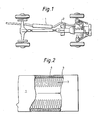
- an invested silencer pipe or muffler 1 may be situated anywhere along the exhaust line 2.
- the muffler may, if necessary, comprise more than one invested section.
- this figure shows muffler 1 as being of greater external diameter than exhaust pipe 2, the extension of this enlargement has been (for purposes of illustration) magnified. It is important that the internal annular space in muffler 1 should not be less than the average diameter of theexhaust line 2. In this way no constriction is built into the exhaust line and no additional back pressure is created.
- Figure 2 is partially broken away view of muffler 1 in which a continuous loop pile investment 3 woven into a suitable backing 4 is bonded directly to the wall of the muffler 6.
- the backing 4 may be bonded chemically to the wall as with a suitable adhesive or form an intricate part of the muffler wall 6, in which case the bonding is mechanical.
- the continuous loop pile may comprise the backing into which the fiber is woven and at the same time form that part of the silencer pipe 1 which is invested in the exhaust line 2.
- conduit 6 shown in axial or transverse section, is provided with an investment of flexible, uni-directional, closely spaced fiber loops 3.
- the acoustic energy present in the gas can be absorbed to a very high degree without incurring any substantial decrease in the kinetic energy of the gas.
- This device then provides an exahust which can be totally silent with minimal back pressure, or, at high velocities of flow, pressure of such low value that the engine maintains higher efficiency than is normally the case.
- a conventional automobile muffler reduces the noise made by the auto engine using a series of baffle plates, packings and walls inside of the muffler. In reducing noise a substantial amount of back pressure is created which decreases the efficiency of the engine. By reducing back pressure the overall operating efficiency and economy of the engine are improved.
- the free end portion of the fiber loops define an opening of about the same cross-sectional area as that of the bore of an incoming exhaust line.
- the minimum cross-sectional area normally required is maintained as an empty space in the fiber loop field, and the annular space between the empty space and the backing at or near the outer casing is occupied by the fiber loops, as described.
- the loop backing may be mechanically or adhesively attached to the conduit interior surface. When so attached an adhesive will be selected to be compatible with the backing and capable of maintaining its integrity during conditions of operation.
- the backing may be supported, or additionally supported, at intervals by a solid keeper which exerts a retaining pressure on the investment from the fluid face, such retainer having a small cross-sectional dimension.
- a solid keeper which exerts a retaining pressure on the investment from the fluid face, such retainer having a small cross-sectional dimension.
- An example of this is an arrangement of small diameter rods or a spiral of rod or wire so introduced that the rod or wire becomes substantially buried in the backing, or it may be attached to the backing by sewing, stapling or other means.
- the keeper may even be, for example, a gauze or mesh having a very high percentage of open area. Clearly the greater the total area of such solid and rigid keeper material which is not well buried in the investment, the less the acoustic absorbent efficiency of the investment will be.
- the pitch or wave length is an aliquant of the total length of uninterruptedl pipe section.
- An aliquot part could conceivably give rise to harmonics of certain frequencies.
- the leading edge of the investment may be protected from attack by the fluid or gas by insert of a short collett, usually of metal, having one end swaged.
- the fiber loops may extend perpendicularly from the internal wall of the conduit and remain so over the whole of their length.
- the fluid flow may cause the fiber loops to bend over at some distance from their point of attachment.
- a ratio will be established involving several factors such as the amount of incident energy and the statistical data relating to the fiber loops,: population per unit area, density or specific gravity, Young's modulus, diameter, and length, particularly that part of the fiber loop investment which is parallel to the direction of fluid flow, effective thickness or depth from the roots when in use, environment humidity, and the length of axial path invested with the fibers.
- the invention is not to be considered limited in any way to the silencing of an internal combustion engine as there are diverse areas in which the principles set forth above also apply.
- Other areas in acoustics where the devices of the invention may be used are those where high noise level impulse waves are produced; the absorbent effect of the investment considerably chops down the initial oscilloscope deflection.
Landscapes
- Engineering & Computer Science (AREA)
- General Engineering & Computer Science (AREA)
- Mechanical Engineering (AREA)
- Chemical & Material Sciences (AREA)
- Combustion & Propulsion (AREA)
- Exhaust Silencers (AREA)
Priority Applications (1)
| Application Number | Priority Date | Filing Date | Title |
|---|---|---|---|
| EP80301748A EP0040657A1 (fr) | 1980-05-27 | 1980-05-27 | Dispositif et procédé pour absorber l'énergie acoustique et dispositifs d'échappement et tuyaux de climatisation ou de chauffage muni de ce dispositif |
Applications Claiming Priority (1)
| Application Number | Priority Date | Filing Date | Title |
|---|---|---|---|
| EP80301748A EP0040657A1 (fr) | 1980-05-27 | 1980-05-27 | Dispositif et procédé pour absorber l'énergie acoustique et dispositifs d'échappement et tuyaux de climatisation ou de chauffage muni de ce dispositif |
Publications (1)
| Publication Number | Publication Date |
|---|---|
| EP0040657A1 true EP0040657A1 (fr) | 1981-12-02 |
Family
ID=8187175
Family Applications (1)
| Application Number | Title | Priority Date | Filing Date |
|---|---|---|---|
| EP80301748A Withdrawn EP0040657A1 (fr) | 1980-05-27 | 1980-05-27 | Dispositif et procédé pour absorber l'énergie acoustique et dispositifs d'échappement et tuyaux de climatisation ou de chauffage muni de ce dispositif |
Country Status (1)
| Country | Link |
|---|---|
| EP (1) | EP0040657A1 (fr) |
Cited By (4)
| Publication number | Priority date | Publication date | Assignee | Title |
|---|---|---|---|---|
| EP0396753A1 (fr) * | 1988-07-28 | 1990-11-14 | Yamato Co: Ltd | Silencieux pour gaz d'echappement de moteurs a combustion |
| EP0548761A2 (fr) * | 1991-12-23 | 1993-06-30 | LTG Lufttechnische GmbH | Dispositif d'étranglement |
| FR2818354A1 (fr) * | 2000-12-18 | 2002-06-21 | Solvay | Dispositif d'insonorisation d'un courant gazeux |
| CN107120822A (zh) * | 2017-04-27 | 2017-09-01 | 海信(山东)空调有限公司 | 一种膨胀型消声器和新风系统 |
Citations (8)
| Publication number | Priority date | Publication date | Assignee | Title |
|---|---|---|---|---|
| US2073951A (en) * | 1935-12-09 | 1937-03-16 | Servais Services Ltd | Silencer for gaseous currents |
| CH199873A (de) * | 1937-07-17 | 1938-09-15 | Kuerth Alfred Ing Dr | Schalldämpfer. |
| DE1697581U (de) * | 1954-10-30 | 1955-04-28 | Walter Schmid | Stachel-einsatz fuer auspuff-schalldaempfer. |
| GB1312416A (en) * | 1970-05-12 | 1973-04-04 | Victa Ltd | Mufflers for internal combustion engines |
| US3920872A (en) * | 1972-11-10 | 1975-11-18 | Armstrong Cork Co | Carpet-faced wallboard |
| US3954031A (en) * | 1975-09-12 | 1976-05-04 | Frelun Engineering Company, Inc. | Sound-deadening device |
| SU635272A1 (ru) * | 1977-06-02 | 1978-11-30 | Предприятие П/Я А-3513 | Глушитель шума газового потока |
| GB2020741A (en) * | 1978-05-12 | 1979-11-21 | Eriksson Gunnar Valdemar | Apparatus for damping noise from exhaust gas outlets |
-
1980
- 1980-05-27 EP EP80301748A patent/EP0040657A1/fr not_active Withdrawn
Patent Citations (9)
| Publication number | Priority date | Publication date | Assignee | Title |
|---|---|---|---|---|
| US2073951A (en) * | 1935-12-09 | 1937-03-16 | Servais Services Ltd | Silencer for gaseous currents |
| CH199873A (de) * | 1937-07-17 | 1938-09-15 | Kuerth Alfred Ing Dr | Schalldämpfer. |
| DE1697581U (de) * | 1954-10-30 | 1955-04-28 | Walter Schmid | Stachel-einsatz fuer auspuff-schalldaempfer. |
| GB1312416A (en) * | 1970-05-12 | 1973-04-04 | Victa Ltd | Mufflers for internal combustion engines |
| US3920872A (en) * | 1972-11-10 | 1975-11-18 | Armstrong Cork Co | Carpet-faced wallboard |
| US3954031A (en) * | 1975-09-12 | 1976-05-04 | Frelun Engineering Company, Inc. | Sound-deadening device |
| SU635272A1 (ru) * | 1977-06-02 | 1978-11-30 | Предприятие П/Я А-3513 | Глушитель шума газового потока |
| GB2020741A (en) * | 1978-05-12 | 1979-11-21 | Eriksson Gunnar Valdemar | Apparatus for damping noise from exhaust gas outlets |
| DE2916873A1 (de) * | 1978-05-12 | 1979-11-22 | Gunnar Valdemar Eriksson | Vorrichtung zur geraeuschdaempfung an luftauslassoeffnungen |
Non-Patent Citations (1)
| Title |
|---|
| "Soviet Inventions Illustrated" Week B 36, 17 October 1979 Section Q 51 & SU - A - 635272 * |
Cited By (8)
| Publication number | Priority date | Publication date | Assignee | Title |
|---|---|---|---|---|
| EP0396753A1 (fr) * | 1988-07-28 | 1990-11-14 | Yamato Co: Ltd | Silencieux pour gaz d'echappement de moteurs a combustion |
| EP0396753A4 (en) * | 1988-07-28 | 1991-03-27 | Yamato Co: Ltd | Silencer for combustion exhaust gas |
| BE1002925A3 (fr) * | 1988-07-28 | 1991-08-20 | Hideo Yoshikawa | Silencieux pour gaz de combustion. |
| EP0548761A2 (fr) * | 1991-12-23 | 1993-06-30 | LTG Lufttechnische GmbH | Dispositif d'étranglement |
| EP0548761A3 (en) * | 1991-12-23 | 1993-11-24 | Ltg Lufttechnische Gmbh | Throttle device |
| FR2818354A1 (fr) * | 2000-12-18 | 2002-06-21 | Solvay | Dispositif d'insonorisation d'un courant gazeux |
| WO2002050420A1 (fr) * | 2000-12-18 | 2002-06-27 | Filterwerk Mann+Hummel Gmbh | Dispositif d'insonorisation d'un courant gazeux |
| CN107120822A (zh) * | 2017-04-27 | 2017-09-01 | 海信(山东)空调有限公司 | 一种膨胀型消声器和新风系统 |
Similar Documents
| Publication | Publication Date | Title |
|---|---|---|
| US5033581A (en) | Muffler for an internal combustion engine | |
| US3710891A (en) | Automotive muffler | |
| US4834214A (en) | Muffler for an internal combustion engine | |
| US4211303A (en) | Sound absorbing device | |
| US1811762A (en) | Exhaust muffler | |
| JP2005514550A (ja) | タービンの騒音吸収機 | |
| US5962821A (en) | Internal combustion engine noise reduction apparatus | |
| EP0774581B1 (fr) | Compresseur équip avec un pièce de sortrie acoustique | |
| US4211305A (en) | Sound absorbing device | |
| CN1024366C (zh) | 离心压缩机消音器 | |
| EP0040657A1 (fr) | Dispositif et procédé pour absorber l'énergie acoustique et dispositifs d'échappement et tuyaux de climatisation ou de chauffage muni de ce dispositif | |
| JPS61112721A (ja) | 排気ガス消音装置 | |
| JP2603131B2 (ja) | 消音装置 | |
| US4211302A (en) | Sound absorbing device | |
| US4211304A (en) | Sound absorbing device | |
| CA1108061A (fr) | Absorption de l'energie acoustique engendree par un fluide | |
| JP2617068B2 (ja) | 脱硝・消音兼用複合装置 | |
| JPH10103728A (ja) | 消音装置 | |
| EP0131350A2 (fr) | Silencieux d'échappement | |
| WO2002066798A1 (fr) | Appareil d'amortissement de resonance dans un tuyau | |
| EP1319156B1 (fr) | Dispositif insonorisant | |
| JPS58117350A (ja) | 内燃機関のエアクリ−ナ | |
| KR101091938B1 (ko) | 제트소음 저감수단을 구비한 엔진 배기가스용 소음기 | |
| RU2300640C1 (ru) | Аэродинамический глушитель выпуска типа "клш" | |
| GB1602466A (en) | Sound absorbing device |
Legal Events
| Date | Code | Title | Description |
|---|---|---|---|
| PUAI | Public reference made under article 153(3) epc to a published international application that has entered the european phase |
Free format text: ORIGINAL CODE: 0009012 |
|
| AK | Designated contracting states |
Designated state(s): BE DE FR IT NL SE |
|
| RAP1 | Party data changed (applicant data changed or rights of an application transferred) |
Owner name: MARTYN, ELIZABETHDE RECOURT Owner name: MATTHEWS, CARL |
|
| 17P | Request for examination filed |
Effective date: 19820526 |
|
| STAA | Information on the status of an ep patent application or granted ep patent |
Free format text: STATUS: THE APPLICATION IS DEEMED TO BE WITHDRAWN |
|
| 18D | Application deemed to be withdrawn |
Effective date: 19831006 |