EP0040290B2 - Elastic rubber mount - Google Patents
Elastic rubber mount Download PDFInfo
- Publication number
- EP0040290B2 EP0040290B2 EP81100930A EP81100930A EP0040290B2 EP 0040290 B2 EP0040290 B2 EP 0040290B2 EP 81100930 A EP81100930 A EP 81100930A EP 81100930 A EP81100930 A EP 81100930A EP 0040290 B2 EP0040290 B2 EP 0040290B2
- Authority
- EP
- European Patent Office
- Prior art keywords
- nozzle
- rubber bearing
- base plate
- disc
- bearing according
- Prior art date
- Legal status (The legal status is an assumption and is not a legal conclusion. Google has not performed a legal analysis and makes no representation as to the accuracy of the status listed.)
- Expired
Links
Images

Classifications
-
- F—MECHANICAL ENGINEERING; LIGHTING; HEATING; WEAPONS; BLASTING
- F16—ENGINEERING ELEMENTS AND UNITS; GENERAL MEASURES FOR PRODUCING AND MAINTAINING EFFECTIVE FUNCTIONING OF MACHINES OR INSTALLATIONS; THERMAL INSULATION IN GENERAL
- F16F—SPRINGS; SHOCK-ABSORBERS; MEANS FOR DAMPING VIBRATION
- F16F13/00—Units comprising springs of the non-fluid type as well as vibration-dampers, shock-absorbers, or fluid springs
- F16F13/04—Units comprising springs of the non-fluid type as well as vibration-dampers, shock-absorbers, or fluid springs comprising both a plastics spring and a damper, e.g. a friction damper
- F16F13/06—Units comprising springs of the non-fluid type as well as vibration-dampers, shock-absorbers, or fluid springs comprising both a plastics spring and a damper, e.g. a friction damper the damper being a fluid damper, e.g. the plastics spring not forming a part of the wall of the fluid chamber of the damper
- F16F13/08—Units comprising springs of the non-fluid type as well as vibration-dampers, shock-absorbers, or fluid springs comprising both a plastics spring and a damper, e.g. a friction damper the damper being a fluid damper, e.g. the plastics spring not forming a part of the wall of the fluid chamber of the damper the plastics spring forming at least a part of the wall of the fluid chamber of the damper
- F16F13/10—Units comprising springs of the non-fluid type as well as vibration-dampers, shock-absorbers, or fluid springs comprising both a plastics spring and a damper, e.g. a friction damper the damper being a fluid damper, e.g. the plastics spring not forming a part of the wall of the fluid chamber of the damper the plastics spring forming at least a part of the wall of the fluid chamber of the damper the wall being at least in part formed by a flexible membrane or the like
- F16F13/105—Units comprising springs of the non-fluid type as well as vibration-dampers, shock-absorbers, or fluid springs comprising both a plastics spring and a damper, e.g. a friction damper the damper being a fluid damper, e.g. the plastics spring not forming a part of the wall of the fluid chamber of the damper the plastics spring forming at least a part of the wall of the fluid chamber of the damper the wall being at least in part formed by a flexible membrane or the like characterised by features of partitions between two working chambers
Definitions
- the invention relates to an elastic rubber bearing, in which a bearing plate, a ring-shaped, conical spring element and a base plate enclose a working space filled with a hydraulic fluid, which is connected by a nozzle to a compensation space, the base plate containing a disk connected to it in a liquid-tight manner, which is movable parallel to the direction of the vibrations introduced and a stop connected to the base plate is provided on both sides of the disc.
- a rubber bearing of the type mentioned is known from FR-A 2372351.
- the compensation space is also elastically limited, which results in a preload in the spring element after the load to be carried has been applied.
- the nozzle is contained in the disc, i.e. relatively flexible with respect to the base plate. Both the damping and the insulating properties are still unsatisfactory.
- Another rubber bearing is known from GB-A 811 748.
- the nozzle is arranged centrally in a diaphragm separating the working space and the compensation space, as a result of which it changes its position continuously and in an undefined manner depending on the amplitude of the vibrations introduced in each case. Vibrations with a large amplitude can only be damped to an insufficient extent. The damping effect of vibrations of this type can be improved by damping the mobility of the membrane. However, a deterioration in the insulating properties compared to vibrations with a low amplitude must be accepted.
- the object of the invention is to develop an elastic rubber bearing in which the damping effect and the insulating effect achieved can be optimized independently of one another, and which thereby has both good damping properties and a good insulating effect.
- a good insulating effect means in particular that structure-borne noise transmission from the engine to the chassis of the vehicle can be largely ruled out.
- the elastic rubber bearing described above is proposed, which is characterized in that the compensation space is limited to the outside by a flexible bellows, that the nozzle for the hydraulic fluid is rigidly assigned to the supporting flange, that the ratio from the Length and the diameter of the nozzle is 4 to 80 and that the ratio of the volume of the working space with the rubber bearing relieved and the volume of the nozzle is 4 to 200.
- the excellent damping effect with regard to the introduction of vibrations with a large amplitude is based not only on the throttling effect caused by the narrow passage cross section of the nozzle, but also on dynamic effects, in particular on the eradication of the vibrations introduced as a result of the back and forth movements of the mass of the liquid volume contained in the nozzle.
- the compensation space should be limited by a flexible bellows with particularly soft elastic properties to prevent pressure build-up inside. If the compensation space is limited by a bellows made of a plastomeric or an elastomeric material, for example PVC or rubber, a particularly soft material must be selected.
- roll membranes if they consist of a flexible fabric that is sealed on one or both sides by a coating of an elastomeric or a plastomeric material.
- the wall thickness of such a Rollmem bran can be reduced to a few tenths of a millimeter.
- a suitably designed bellows can be arranged, for example, in a protective basket or pot made of a metallic material, which is firmly connected to the bearing plate. Appropriate ventilation openings ensure that the membrane can move freely.
- the disc is sealed against the bearing plate and can move freely. It is generally conceivable to give the disk the shape of a floating piston, wherein the mobility can be hindered by the frictional forces to be overcome.
- the bearing play of such a floating piston which may have the shape of a flat plate made of rubber or plastic, for example, must therefore be measured in such a way that on the one hand the mobility is not impeded and on the other hand an adequate seal with respect to the bearing plate is ensured.
- the establishment of a significant hydraulic connection between the work space and between the compensation space is undesirable in the sense of the present invention.
- a round shape is generally preferred. However, depending on the shape of the elastic rubber bearing, it is also possible to choose different shapes, for example an oval shape. In all cases, the aim is for the movable part of the disk to cover at least 50% of the inside diameter of the working area. This largely suppresses cross currents and other undesirable effects when small vibrations are introduced.
- the disc can be flexible and, for example, made of a rubber-elastic material. In this case, it is necessary, depending on the flexibility, to replace the stops with grids which are connected to the supporting flange and have regularly recurring cutouts, the surface area of which is 40 to 90%.
- the thickness of the disc can be reduced in the area of the saving cross section in order to enable particularly easy mobility.
- the respective distance from the stops arranged on both sides is the same in mirror image, but it can be varied over the diameter of the disk and, for example, in the middle, where greater deformations occur, can be considerably larger than in the area of the edge zones.
- a uniform increase towards the center is possible, but also an increase in the distance, which asymptotically approaches a maximum value at about% of the distance from the center of the disk.
- the nozzle can be a recess in the base plate surrounding the disc, the outlet openings of which end tangentially in the respective rooms on both sides. It is also possible to arrange two mirror-image stop plates in the base plate, which cannot move in a direction parallel to the direction of the vibrations introduced, but are sealed with respect to the base plate and rotatable relative to one another. Here, too, there is a recess in the central area for receiving the pane and a large number of openings for forming the stop grid for the pane.
- the stop grille is surrounded by the spirally arranged recess, which begins on the surface of the end face of one stop plate, assumes increasing depth in the course, finally penetrates the stop plate and continues in the same direction on the back with decreasing depth.
- the usual hydraulic oils can be used as the hydraulic fluid. Special care must be taken to ensure that the selected liquid has a balanced viscosity in the range of the temperatures to be expected under operating conditions. From this point of view, it has proven advantageous to use a mixture of glycol and water, preferably of glycerol and water, the two substances preferably being mixed with one another in a ratio of 1: 1 to 2: 1.
- the rubber bearing shown consists of a bearing plate 1 with a bore arranged therein with a thread for fastening a vibrating machine element to be mounted thereon, for example a motor or a wheel bearing.
- the bearing plate has a circular shape, and is non-releasably vulcanized to the base plate 3 by a conical spring element 2 made of a rubber-elastic material.
- the surfaces delimiting the spring element with respect to the bearing plate and with respect to the base plate are aligned essentially parallel to one another.
- the base plate is also provided with a flange with a plurality of bores in order to enable a screw connection, for example on a vehicle body.
- the base plate has on the inside a circumferential, angularly inwardly open recess in which the stop plates 4, 5 and the flexible bellows 7 are anchored liquid-tight with a retaining ring 10.
- the stop plates have grid-like openings 12 in the central region, and the cutouts are dimensioned such that there is an axial distance on both sides from the movable disk 11 made of an elastomeric material. The disk is clamped in a liquid-tight manner outside the grid between the two stop plates with a circumferential bead.
- the thickness of the disc is reduced in a radial direction within the bead in order to obtain improved mobility. It can also be freely movable in the recess in the axial direction without a frictional clamping.
- the two stop plates are also penetrated by the nozzle 6, which spirally surrounds the grid formed by the openings 12, the recesses on both sides should merge into one another as evenly as possible.
- small angles have proven useful, for example values of less than 10 °, preferably in a range of 1 to 4 °. If, on the other hand, several nozzles are evenly spaced around the circumference of the stop plates, then there may be a need for geometrical reasons to choose larger pitch angles, for example those in a range from 20 to 30 °. Regardless of this, it is desirable in all cases that the ends on both sides lead tangentially into the working space 8, and on the other hand into the compensation space 9.
- the compensation space is limited at the bottom by a flexible bellows 7, which is designed as a rolling membrane.
- This consists of a soft rubber layer, which is reinforced by a fabric made of polyester threads.
- the roll membrane has an average wall thickness of 0.3 mm. Because of its mechanical sensitivity, it is particularly protected by an additional protective cap 14 made of sheet steel.
- the protective cap has a ventilation opening 13 in order to ensure free movement of the rolling membrane. It is also possible to make the protective cap robust and use it instead of a flange on the base plate to anchor the rubber bearing.
- the hydraulic fluid used is a 1: 2 mixture of water and glycerin. It has a uniform viscosity in a temperature range from -30 ° to + 100 ° C, and foam formation which affects the damping effect does not take place even when high frequencies are introduced.
- the free passage cross section of the nozzle is 43 mm 2 with a volume of the working space of 58 cm 3 .
- Fig. 2 the two interconnected stop plates 4, 5 are shown in plan view.
- the nozzle 6 formed by the recess penetrates in a spiral turn the individual stop plate with a thickness of approx. 6 mm over a length of approx. 430 ° with a uniform slope.
- the continuation of the cutout in the cutout of the counter plate assigned in mirror image results in a constant cross section over almost the entire length.
- the length can be adjusted by mutually rotating the two stop plates, which is to be illustrated by FIG. 4.
- Fig. 4 refers to the course of the nozzle 6 through the two stop plates 4, 5, wherein for the sake of clarity, a true-to-scale reproduction has been omitted. Compared to the thickness of the stop plates, the length of the nozzle is therefore shown in a much shorter form.
- the calculated diameter of the nozzle results in the cross-section shown, which differs from a round profile, as a square root of the product of factor 1.27 and the cross-sectional area of the nozzle.
- Different cross-sectional shapes can be used accordingly in the claimed formula. They have no influence on how it works.
- the length of the nozzle corresponds to the distance on which the profile of the recess is delimited by solid walls on all sides.
- the inlet and outlet wedges of the same pitch adjoining this area on both sides are not counted and are not taken into account.
- the length is designated in Fig. 4 with "L”.
- the volume that results when the rubber bearing is relieved is used as the volume of the work area.
Description
Die Erfindung betrifft ein elastisches Gummilager, bei dem eine Lagerplatte, ein ringförmig ausgebildetes, kegeliges Federelement und eine Bodenplatte einen mit einer hydraulischen Flüssigkeit gefüllten Arbeitsraum umschliessen, der durch eine Düse mit einem Ausgleichsraum verbunden ist, wobei die Bodenplatte eine flüssigkeitsdicht damit verbundene Scheibe enthält, die parallel zur Richtung der eingeleiteten Schwingungen beweglich ist und wobei beiderseits der Scheibe ein mit der Bodenplatte verbundener Anschlag vorgesehen ist.The invention relates to an elastic rubber bearing, in which a bearing plate, a ring-shaped, conical spring element and a base plate enclose a working space filled with a hydraulic fluid, which is connected by a nozzle to a compensation space, the base plate containing a disk connected to it in a liquid-tight manner, which is movable parallel to the direction of the vibrations introduced and a stop connected to the base plate is provided on both sides of the disc.
Ein Gummilager der eingangs genannten Art ist aus der FR-A 2372351 bekannt. Zusätzlich zu dem Arbeitsraum ist dabei auch der Ausgleichsraum elastisch begrenzt, was nach dem Aufbringen der zu tragenden Last eine Vorspannung in dem Federelement zur Folge hat. Die Düse ist in der Scheibe enthalten, d.h. relativ beweglich in bezug auf die Bodenplatte. Sowohl die Dämpfungs- als auch die Isoliereigenschaften sind noch wenig befriedigend.A rubber bearing of the type mentioned is known from FR-A 2372351. In addition to the working space, the compensation space is also elastically limited, which results in a preload in the spring element after the load to be carried has been applied. The nozzle is contained in the disc, i.e. relatively flexible with respect to the base plate. Both the damping and the insulating properties are still unsatisfactory.
Ein anderes Gummilager ist aus GB-A 811 748 bekannt.Another rubber bearing is known from GB-A 811 748.
Die Düse ist dabei zentrisch in einer den Arbeitsraum und den Ausgleichsraum voneinander trennenden Membran angeordnet, wodurch sie ihre Lage in Abhängigkeit von der Amplitude der jeweils eingeleiteten Schwingungen stetig und in undefinierter Weise verändert. Schwingungen mit grosser Amplitude können dadurch nur in einem unzureichenden Masse gedämpft werden. Eine Verbesserung der erzielten Dämpfungswirkung von Schwingungen dieser Art ist durch eine Dämpfung der Beweglichkeit der Membrane möglich. Dabei muss aber eine Verschlechterung der Isoliereigenschaften gegenüber Schwingungen mit niedriger Amplitude in Kauf genommen werden.The nozzle is arranged centrally in a diaphragm separating the working space and the compensation space, as a result of which it changes its position continuously and in an undefined manner depending on the amplitude of the vibrations introduced in each case. Vibrations with a large amplitude can only be damped to an insufficient extent. The damping effect of vibrations of this type can be improved by damping the mobility of the membrane. However, a deterioration in the insulating properties compared to vibrations with a low amplitude must be accepted.
Der Erfindung liegt die Aufgabe zugrunde, ein elastisches Gummilager zu entwickeln, bei dem die erzielte Dämpfungswirkung und die erzielte lsolierwirkung unabhängig voneinander optimiert werden können, und das dadurch sowohl gute Dämpfungseigenschaften als auch eine gute Isolierwirkung aufweist. Unter einer guten Isolierwirkung ist in bezug auf eine Verwendung als Motorlager insbesondere zu verstehen, dass eine Körperschallübertragung vom Motor auf das Chassis des Fahrzeuges weitgehend ausgeschlossen werden kann.The object of the invention is to develop an elastic rubber bearing in which the damping effect and the insulating effect achieved can be optimized independently of one another, and which thereby has both good damping properties and a good insulating effect. With regard to use as an engine mount, a good insulating effect means in particular that structure-borne noise transmission from the engine to the chassis of the vehicle can be largely ruled out.
Zur Lösung dieser Aufgabe wird eine Weiterentwicklung des eingangs beschriebenen, elastischen Gummilagers vorgeschlagen, die dadurch gekennzeichnet ist, dass der Ausgleichsraum nach aussen durch einen flexiblen Balg begrenzt ist, dass die Düse für die hydraulische Flüssigkeit dem Tragflansch starr zugeordnet ist, dass das Verhältnis aus der Länge und dem Durchmesser der Düse 4 bis 80 beträgt und dass das Verhältnis aus dem Volumen des Arbeitsraumes bei entlastetem Gummilager und dem Volumen der Düse 4 bis 200 beträgt.To solve this problem, a further development of the elastic rubber bearing described above is proposed, which is characterized in that the compensation space is limited to the outside by a flexible bellows, that the nozzle for the hydraulic fluid is rigidly assigned to the supporting flange, that the ratio from the Length and the diameter of the nozzle is 4 to 80 and that the ratio of the volume of the working space with the rubber bearing relieved and the volume of the nozzle is 4 to 200.
Die vorteilhaften Eigenschaften des vorgeschlagenen Gummilagers ergeben sich aus der folgenden Funktion:
- Das vorgeschlagene Gummilager ist ein hydraulisches Einkammer-Gummilager, d.h. der hydraulische Innendruck in dem Arbeitsraum ist unabhängig von der statischen Belastung, und die sich infolge der eingeleiteten Schwingungen darin ergebenden Druckveränderungen sind rein dynamischer Natur. Sie haben keinen Einfluss auf die Federungscharakteristik des den Arbeitsraum in einem Teilbereich begrenzenden Federelementes aus gummielastischem Werkstoff. Dieses kann in seinem Querschnitt infolgedessen beliebig gestaltet werden, und damit auch so, dass eine optimale Isolierung von eingeleiteten Schwingungen mit einer kleinen Amplitude gewährleistet ist. Schwingungen dieser Art können dadurch beschrieben werden, dass das von dem Federelement jeweils verdrängte Flüssigkeitsvolumen kleiner sein muss als das durch eine synchrone Ausweichbewegung der Scheibe aufnehmbare Volumen. Eine Verschiebung von Flüssigkeitsbestandteilen durch die Düse in den Ausgleichsraum findet bei Einleitung derartiger Schwingungen nicht statt.
- The proposed rubber bearing is a hydraulic single-chamber rubber bearing, ie the hydraulic internal pressure in the work space is independent of the static load, and the pressure changes resulting therein as a result of the vibrations introduced are purely dynamic in nature. They have no influence on the suspension characteristics of the spring element made of rubber-elastic material that delimits the working area in a partial area. As a result, its cross-section can be designed as desired, and thus also in such a way that optimal isolation of introduced vibrations with a small amplitude is ensured. Vibrations of this type can be described in that the volume of liquid displaced by the spring element must be smaller than the volume that can be absorbed by a synchronous evasive movement of the disk. A displacement of liquid components through the nozzle into the compensation space does not take place when such vibrations are introduced.
Bei Einleitung von Schwingungen mit einer grösseren Amplitude wird die freie Beweglichkeit der Scheibe durch die beiderseits davon angeordneten Anschläge behindert, und es kommt zu einem dynamischen Druckaufbau in dem Arbeitsraum mit der Folge einer synchronen Verschiebung des in der Düse enthaltenen Flüssigkeitsvolumens. Bei Verwendung üblicher Hydrauliköle ergibt sich dann ein optimaler Dämpfungseffekt für die eingeleiteten Schwingungen, wenn das Verhältnis aus der Länge und dem Durchmesser der Düse 4 bis 80 beträgt und wenn das Verhältnis aus dem Volumen des Arbeitsraumes und dem Volumen der Düse 4 bis 200 beträgt, wobei ein Bereich von 10 bis 30 bzw. 8 bis 60 bevorzugt wird. Die ausgezeichnete Dämpfungswirkung in bezug auf die Einleitung von Schwingungen mit grosser Amplitude beruht neben der durch den engen Durchlassquerschnitt der Düse bedingten Drosselwirkung auch auf dynamischen Effekten, insbesondere auf der Tilgung der eingeleiteten Schwingungen infolge Hin- und Herbewegungen der Masse des in der Düse enthaltenen Flüssigkeitsvolumens. Der Ausgleichsraum soll zur Verhinderung eines Druckaufbaues im Inneren durch einen flexiblen Balg mit besonders weichelastischen Eigenschaften begrenzt sein. Sofern der Ausgleichsraum durch einen Faltenbalg aus einem plastomeren oder einem elastomeren Werkstoff begrenzt ist, beispielsweise aus PVC oder Gummi, muss ein besonders weicher Werkstoff ausgewählt werden. Unter Verwendung von Rollmembranen lassen sich gute Ergebnisse erzielen, wenn diese aus einem flexiblen Gewebe bestehen, das ein- oder beidseitig durch eine Beschichtung aus einem elastomeren oder einem plastomeren Werkstoff abgedichtet ist. Die Wandstärke einer derartigen Rollmembran kann bis auf wenige zehntel Millimeter reduziert sein. Um eine mechanische Beschädigung zu verhindern, kann ein entsprechend ausgebildeter Balg beispielsweise in einem Schutzkorb oder -topf aus einem metallischen Werkstoff angeordnet werden, der fest mit der Lagerplatte verbunden ist. Durch zweckmässig angebrachte Entlüftungsöffnungen ist dabei eine freie Beweglichkeit der Membran zu gewährleisten.When vibrations with a larger amplitude are introduced, the free movement of the disk is hindered by the stops arranged on both sides thereof, and there is a dynamic pressure build-up in the working space with the result of a synchronous displacement of the liquid volume contained in the nozzle. When using conventional hydraulic oils, there is an optimal damping effect for the vibrations introduced if the ratio of the length and the diameter of the nozzle is 4 to 80 and if the ratio of the volume of the working space and the volume of the nozzle is 4 to 200, whereby a range of 10 to 30 or 8 to 60 is preferred. The excellent damping effect with regard to the introduction of vibrations with a large amplitude is based not only on the throttling effect caused by the narrow passage cross section of the nozzle, but also on dynamic effects, in particular on the eradication of the vibrations introduced as a result of the back and forth movements of the mass of the liquid volume contained in the nozzle. The compensation space should be limited by a flexible bellows with particularly soft elastic properties to prevent pressure build-up inside. If the compensation space is limited by a bellows made of a plastomeric or an elastomeric material, for example PVC or rubber, a particularly soft material must be selected. Good results can be achieved using roll membranes if they consist of a flexible fabric that is sealed on one or both sides by a coating of an elastomeric or a plastomeric material. The wall thickness of such a Rollmem bran can be reduced to a few tenths of a millimeter. To prevent mechanical damage, a suitably designed bellows can be arranged, for example, in a protective basket or pot made of a metallic material, which is firmly connected to the bearing plate. Appropriate ventilation openings ensure that the membrane can move freely.
Die Scheibe ist gegenüber der Lagerplatte abgedichtet und frei beweglich. Es ist generell denkbar, der Scheibe die Gestalt eines Schwebekolbens zu geben, wobei die Beweglichkeit durch die zu überwindenden Reibungskräfte behindert werden kann. Das Lagerspiel eines solchen Schwebekolbens, der beispielsweise die Gestalt einer ebenen Platte aus Gummi oder Kunststoff haben kann, muss deshalb so gemessen werden, dass einerseits die Beweglichkeit nicht behindert wird, und dass andererseits eine ausreichende Abdichtung gegenüber der Lagerplatte gewährleistet ist. Das Zustandekommen einer nennenswerten hydraulischen Verbindung zwischen dem Arbeitsraum und zwischen dem Ausgleichsraum ist im Sinne der vorliegenden Erfindung unerwünscht.The disc is sealed against the bearing plate and can move freely. It is generally conceivable to give the disk the shape of a floating piston, wherein the mobility can be hindered by the frictional forces to be overcome. The bearing play of such a floating piston, which may have the shape of a flat plate made of rubber or plastic, for example, must therefore be measured in such a way that on the one hand the mobility is not impeded and on the other hand an adequate seal with respect to the bearing plate is ensured. The establishment of a significant hydraulic connection between the work space and between the compensation space is undesirable in the sense of the present invention.
Es ist auch möglich, den Schwebekolben durch ein membranartiges Übergangsstück flüssigkeitsdicht, jedoch beweglich mit der Bodenplatte zu verbinden. Dabei lässt sich aber eine gewisse Beeinträchtigung der freien Beweglichkeit des Kolbens nicht vermeiden, was sich in schwierigen Fällen nachteilig auf die Entkopplung hochfrequenter Schwingungen und damit der Isoliereigenschaften des Gummilagers auswirken kann.It is also possible to connect the floating piston to the base plate in a liquid-tight but moveable manner by means of a membrane-like transition piece. However, a certain impairment of the free movement of the piston cannot be avoided, which can have a disadvantageous effect on the decoupling of high-frequency vibrations and thus the insulating properties of the rubber bearing in difficult cases.
Im allgemeinen wird eine runde Form bevorzugt. Es ist jedoch in Abhängigkeit von der Gestalt des elastischen Gummilagers auch möglich, gegebenenfalls abweichende Formen zu wählen, beispielsweise eine ovale Gestalt. In allen Fällen wird angestrebt, dass der bewegliche Teil der Scheibe wenigsten 50% des Innendurchmessers des Arbeitsraumes überdeckt. Hierdurch lassen sich Querströmungen und andere unerwünschte Effekte bei Einleitung kleiner Schwingungen weitgehend unterdrücken.A round shape is generally preferred. However, depending on the shape of the elastic rubber bearing, it is also possible to choose different shapes, for example an oval shape. In all cases, the aim is for the movable part of the disk to cover at least 50% of the inside diameter of the working area. This largely suppresses cross currents and other undesirable effects when small vibrations are introduced.
Die Scheibe kann flexibel ausgebildet sein und beispielsweise aus einem gummielastischen Werkstoff bestehen. In diesem Falle ist es notwendig, die Anschläge in Abhängigkeit von der Flexibilität durch mit dem Tragflansch verbundene, regelmässig wiederkehrende Aussparungen aufweisende Gitter zu ersetzen, deren Oberflächenanteil 40 bis 90% beträgt. Die Dicke der Scheibe kann im Bereich des Einsparungsquerschnittes vermindert sein, um eine besonders leichte Beweglichkeit zu ermöglichen. Der jeweilige Abstand von den beiderseits angeordneten Anschlägen ist spiegelbildlich gleich, er kann jedoch über dem Durchmesser der Scheibe variiert sein, und beispielsweise in der Mitte, wo stärkere Deformationen auftreten, wesentlich grösser sein als im Bereich der Randzonen.The disc can be flexible and, for example, made of a rubber-elastic material. In this case, it is necessary, depending on the flexibility, to replace the stops with grids which are connected to the supporting flange and have regularly recurring cutouts, the surface area of which is 40 to 90%. The thickness of the disc can be reduced in the area of the saving cross section in order to enable particularly easy mobility. The respective distance from the stops arranged on both sides is the same in mirror image, but it can be varied over the diameter of the disk and, for example, in the middle, where greater deformations occur, can be considerably larger than in the area of the edge zones.
Es ist eine gleichmässige Zunahme zur Mitte hin möglich, jedoch auch eine Zunahme des Abstandes, der sich asymptotisch bei etwa % des Abstandes vom Mittelpunkt der Scheibe einem Maximalwert nähert.A uniform increase towards the center is possible, but also an increase in the distance, which asymptotically approaches a maximum value at about% of the distance from the center of the disk.
Die Düse kann eine die Scheibe umgebende Aussparung der Bodenplatte sein, deren Austrittsöffnungen beiderseits tangential in den jeweiligen Räumen enden. Es ist auch möglich, in der Bodenplatte zwei spiegelbildliche Anschlagplatten anzuordnen, die in einer Richtung parallel zur Richtung der eingeleiteten Schwingungen nicht beweglich, jedoch gegenüber der Bodenplatte abgedichtet und gegeneinander drehbar sind. Auch hierbei ist im mittleren Bereich eine Aussparung zur Aufnahme der Scheibe vorgesehen sowie eine Vielzahl von Durchbrechungen zur Bildung des Anschlaggitters für die Scheibe. Das Anschlaggitter ist von der spiralig angeordneten Aussparung umgeben, die auf der Oberfläche der Stirnseite der einen Anschlagplatte beginnend, im Verlauf eine zunehmende Tiefe annimmt, die Anschlagplatte schliesslich durchdringt und auf der Rückseite gleichsinnig mit abnehmender Tiefe fortgesetzt ist. Durch die spiegelbildliche Zusammenfassung beider Anschlagplatten und ein gegenseitiges Verdrehen lässt sich die tatsächliche Länge und, bedingt, der Querschnitt der von den beiderseitigen Aussparungen gebildeten Düse sehr exakt einstellen, wodurch die erzielte Dämpfung grössenordnungsmässig optimiert und auf einen bestimmten Frequenzbereich eingestellt werden kann. Es wurde gefunden, dass sich bei einer entsprechenden Ausführung bei der Einfederung der Lagerplatte in Richtung der Austrittsöffnungen eine gleichgerichtete Kreisströmung der hydraulischen Flüssigkeit im Arbeitsraum und im Ausgleichsraum ausbildet, deren Richtung beim Ausfedern spontan wechselt. Bei der Abbremsung der in beiden Räumen rotierenden Flüssigkeitsmassen und deren erneuter Beschleunigung wird ein Teil der eingeleiteten Schwingungsenergie irreversibel vernichtet, wodurch der Effekt der Verwendung einer relativ langen Düse zwischen den beiden Räumen wesentlich verstärkt wird. Besonders gute Eigenschaften lassen sich durch Verwendung mehrerer Düsen erzielen, die auf dem Umfang in gleichmässigen Abständen verteilt, und deren Austrittsöffnungen gleichsinnig orientiert sind.The nozzle can be a recess in the base plate surrounding the disc, the outlet openings of which end tangentially in the respective rooms on both sides. It is also possible to arrange two mirror-image stop plates in the base plate, which cannot move in a direction parallel to the direction of the vibrations introduced, but are sealed with respect to the base plate and rotatable relative to one another. Here, too, there is a recess in the central area for receiving the pane and a large number of openings for forming the stop grid for the pane. The stop grille is surrounded by the spirally arranged recess, which begins on the surface of the end face of one stop plate, assumes increasing depth in the course, finally penetrates the stop plate and continues in the same direction on the back with decreasing depth. The mirror-image combination of both stop plates and a mutual twisting allows the actual length and, to a certain extent, the cross-section of the nozzle formed by the recesses on both sides to be set very precisely, so that the damping achieved can be optimized in terms of magnitude and adjusted to a specific frequency range. It has been found that with a corresponding design, when the bearing plate is deflected in the direction of the outlet openings, a rectified circular flow of the hydraulic fluid is formed in the work space and in the compensation space, the direction of which changes spontaneously when rebounding. When the liquid masses rotating in both rooms are decelerated and accelerated again, part of the vibrational energy introduced is irreversibly destroyed, which significantly increases the effect of using a relatively long nozzle between the two rooms. Particularly good properties can be achieved by using several nozzles which are evenly spaced around the circumference and whose outlet openings are oriented in the same direction.
Als hydraulische Flüssigkeit können die üblichen Hydrauliköle verwendet werden. Es bedarf der besonderen Beachtung, dass die ausgewählte Flüssigkeit im Bereich der unter Betriebsbedingungen zu erwartenden Temperaturen eine ausgeglichene Viskosität aufweist. Als vorteilhafter hat sich unter diesem Gesichtspunkt die Verwendung eines Gemisches aus Glykol und Wasser bewährt, vorzugsweise aus Glycerin und Wasser, wobei die beiden Substanzen vorzugsweise in einem Verhältnis von 1:1 bis 2:1 untereinander vermischt werden.The usual hydraulic oils can be used as the hydraulic fluid. Special care must be taken to ensure that the selected liquid has a balanced viscosity in the range of the temperatures to be expected under operating conditions. From this point of view, it has proven advantageous to use a mixture of glycol and water, preferably of glycerol and water, the two substances preferably being mixed with one another in a ratio of 1: 1 to 2: 1.
In der Zeichnung ist Bezug genommen auf eine beispielhafte Ausführung des erfindungsgemässen Gummilagers. Es zeigt
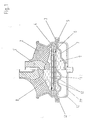
- Fig. ein Gummilager in längsgeschnittener Darstellung. Der linke Teil der Darstellung nimmt Bezug auf eine Belastungssituation, in der die Lagerplatte ausgefedert ist, der rechte Teil der Darstellung nimmt Bezug auf eine Belastungssituation, in der die Lagerplatte unter Einwirkung einer Last eingefedert ist.
- Fig. zeigt die
Anschlagplatten - Fig. 3 zeigt die Anschlagplatten gemäss Fig. 1 in längsgeschnittener Darstellung.
- Fig.4 nimmt Bezug auf einen Längsschnitt durch die
Düse 6 bei einer Lagerplatte entsprechend den Fig. 2und 3.
- Fig. A rubber bearing in a longitudinal section. The left part of the illustration refers to a load situation in which the bearing plate is spring-loaded, the right part of the representation relates to a load situation in which the bearing plate is spring-loaded under the influence of a load.
- Fig. Shows the
stop plates - FIG. 3 shows the stop plates according to FIG. 1 in a longitudinal section.
- FIG. 4 refers to a longitudinal section through the
nozzle 6 in the case of a bearing plate corresponding to FIGS. 2 and 3.
Das dargestellte Gummilager besteht aus einer Lagerplatte 1 mit einer darin angeordneten Bohrung mit einem Gewinde zur Befestigung eines darauf zu lagernden, schwingenden Maschinenelementes, beispielsweise eines Motors oder eines Radlagers. Die Lagerplatte hat eine kreisförmige Gestalt, und sie ist durch ein kegeliges Federelement 2 aus einem gummielastischen Werkstoff unlösbar an die Bodenplatte 3 anvulkanisiert. Die das Federelement gegenüber der Lagerplatte und gegenüber der Bodenplatte begrenzenden Flächen sind im wesentlichen zueinander parallel ausgerichtet. Die Bodenplatte ist darüber hinaus mit einem Flansch mit mehreren Bohrungen versehen, um eine Verschraubung beispielsweise an einer Fahrzeugkarosserie zu ermöglichen.The rubber bearing shown consists of a bearing plate 1 with a bore arranged therein with a thread for fastening a vibrating machine element to be mounted thereon, for example a motor or a wheel bearing. The bearing plate has a circular shape, and is non-releasably vulcanized to the
Die Bodenplatte weist auf der Innenseite eine umlaufende, winkelförmig nach innen geöffnete Aussparung auf, in der die Anschlagplatten 4, 5 und der flexible Balg 7 mit einem Haltering 10 flüssigkeitsdicht verankert sind. Die Anschlagplatten weisen im mittleren Bereich gitterartige Durchbrechungen 12 auf, und die Aussparungen sind so bemessen, dass sich beiderseits ein axialer Abstand von der beweglichen Scheibe 11 aus einem elastomeren Werkstoff ergibt. Die Scheibe ist mit einem umlaufenden Wulst ausserhalb des Gitters zwischen den beiden Anschlagplatten flüssigkeitsdicht eingespannt.The base plate has on the inside a circumferential, angularly inwardly open recess in which the
Die Dicke der Scheibe ist in einer radialen Richtung innerhalb des Wulstes vermindert, um eine verbesserte Beweglichkeit zu erhalten. Sie kann auch ohne eine kraftschlüssige Einspannung in axialer Richtung frei beweglich in der Aussparung gelagert sein.The thickness of the disc is reduced in a radial direction within the bead in order to obtain improved mobility. It can also be freely movable in the recess in the axial direction without a frictional clamping.
Die beiden Anschlagplatten werden ausserdem von der das durch die Durchbrechungen 12 gebildete Gitter spiralig umgebenden Düse 6 durchdrungen, wobei die beiderseitigen Aussparungen möglichst gleichmäsig ineinander übergehen sollen. Im Hinblick auf eine gute Einstellmöglichkeit der Länge der Düse durch ein gegenseitiges Verdrehen der beiden Anschlagplatten 4, 5 gegeneinander haben sich kleine Winkel bewährt, beispielsweise Werte von weniger als 10°, bevorzugt in einem Bereich von 1 bis 4°. Sind auf dem Umfang der Anschlagplatten hingegen mehrere Düsen in gleichmässigen Abständen verteilt, dann kann sich aus geometrischen Gründen die Notwendigkeit ergeben, grössere Steigungswinkel zu wählen, beispielsweise solche in einem Bereich von 20 bis 30°. Ungeachtet dessen ist es in allen Fällen anzustreben, dass die beiderseitigen Enden einerseits tangential in den Arbeitsraum 8 münden, andererseits in den Ausgleichsraum 9.The two stop plates are also penetrated by the
Der Ausgleichsraum wird nach unten durch einen flexiblen Balg 7 begrenzt, der als Rollmembran ausgebildet ist. Diese besteht aus einer weichen Gummischicht, die durch ein Gewebe aus Polyesterfäden verstärkt ist.The compensation space is limited at the bottom by a flexible bellows 7, which is designed as a rolling membrane. This consists of a soft rubber layer, which is reinforced by a fabric made of polyester threads.
Die Rollmembran hat eine durchschnittliche Wandstärke von 0,3 mm. Sie ist wegen ihrer mechanischen Empfindlichkeit durch eine zusätzliche Schutzkappe 14 aus Stahlblech besonders geschützt. Die Schutzkappe weist eine Entlüftungsöffnung 13 auf, um eine freie Beweglichkeit der Rollmembrane zu gewährleisten. Es ist daneben möglich, die Schutzkappe robust auszuführen und anstelle eines Flansches der Bodenplatte zur Verankerung des Gummilagers zu verwenden.The roll membrane has an average wall thickness of 0.3 mm. Because of its mechanical sensitivity, it is particularly protected by an additional
Die verwendete hydraulische Flüssigkeit ist ein Gemisch aus Wasser und Glycerin im Verhältnis 1:2. Sie weist in einem Temperaturbereich von -30° bis +100°C eine gleichmässige Viskosität auf, und eine die Dämpfungswirkung beeinträchtigende Schaumbildung findet auch bei Einleitung hoher Frequenzen nicht statt. Der freie Durchlassquerschnitt der Düse beträgt bei einem Volumen des Arbeitsraumes von 58 cm3 43 mm2.The hydraulic fluid used is a 1: 2 mixture of water and glycerin. It has a uniform viscosity in a temperature range from -30 ° to + 100 ° C, and foam formation which affects the damping effect does not take place even when high frequencies are introduced. The free passage cross section of the nozzle is 43 mm 2 with a volume of the working space of 58 cm 3 .
In Fig. 2 sind die beiden untereinander verbundenen Anschlagplatten 4, 5 in der Draufsicht wiedergegeben. Die durch die Aussparung gebildete Düse 6 durchdringt in einer spiraligen Windung die einzelne Anschlagplatte mit einer Dicke von ca. 6 mm auf einer Länge von ca. 430° mit gleichmässiger Steigung. Durch die Fortsetzung der Aussparung in der Aussparung der spiegelbildlich zugeordneten Gegenplatte ergibt sich nahezu auf der gesamten Länge ein gleichbleibender Querschnitt. Die Länge kann durch ein gegenseitiges Verdrehen der beiden Anschlagplatten eingestellt werden, was durch Fig. 4 verdeutlicht werden soll. Fig. 4 nimmt Bezug auf den Verlauf der Düse 6 durch die beiden Anschlagplatten 4, 5, wobei aus Gründen der Anschaulichkeit auf eine massstäbliche Wiedergabe verzichtet wurde. Im Vergleich zur Dicke der Anschlagplatten ist die Länge der Düse deshalb in wesentlich verkürzter Form wiedergegeben. Es ist jedoch erkennbar, dass bei einer relativen Verschiebung der Anschlagplatte 5 in bezug auf die Anschlagplatte 4 eine Verlängerung bzw. eine Verkürzung der Düse 6 eintritt, und in begrenztem Masse auch von deren Querschnitt. Dieser Vorgang wird bei den Anschlagplatten gemäss Fig. 2 durch ein gegenseitiges Verdrehen praktisch nachvollzogen. Das vorgeschlagene Gummilager lässt sich dadurch hinsichtlich der erzielten Dämpfungswirkung sowohl grössenmässig optimieren als auch hinsichtlich der Lage der Dämpfungswirkung auf einen bestimmten Frequenzbereich einstellen. Die Anschlagplatten können aus Metall oder Kunststoff bestehen, wobei jedoch eine Ausführung aus Aluminiumdruckguss wegen der grossen mechanischen Steifigkeit bevorzugt wird.In Fig. 2, the two
Der rechnerische Durchmesser der Düse ergibt sich bei dem dargestellten, von einem runden Profil abweichenden Querschnitt als quadratische Wurzel aus dem Produkt des Faktors 1,27 und der Querschnittsfläche der Düse. Abweichende Querschnittsformen können entsprechend in die beanspruchte Formel eingesetzt werden. Sie haben keinen Einfluss auf die Wirkungsweise.The calculated diameter of the nozzle results in the cross-section shown, which differs from a round profile, as a square root of the product of factor 1.27 and the cross-sectional area of the nozzle. Different cross-sectional shapes can be used accordingly in the claimed formula. They have no influence on how it works.
Die Länge der Düse entspricht der Strecke, auf der das Profil der Aussparung auf allen Seiten durch feste Wände begrenzt ist. Die sich an diesen Bereich beiderseits anschliessenden Ein- und Auslaufkeile gleicher Steigung werden nicht mitgerechnet und bleiben ausser Betracht. Die Länge ist in Fig. 4 mit «L» bezeichnet.The length of the nozzle corresponds to the distance on which the profile of the recess is delimited by solid walls on all sides. The inlet and outlet wedges of the same pitch adjoining this area on both sides are not counted and are not taken into account. The length is designated in Fig. 4 with "L".
Als Volumen des Arbeitsraumes wird das Volumen eingesetzt, das sich bei entlastetem Gummilager ergibt.The volume that results when the rubber bearing is relieved is used as the volume of the work area.
Claims (7)
Applications Claiming Priority (2)
| Application Number | Priority Date | Filing Date | Title |
|---|---|---|---|
| DE3019337A DE3019337C2 (en) | 1980-05-21 | 1980-05-21 | Elastic rubber mount |
| DE3019337 | 1980-05-21 |
Publications (4)
| Publication Number | Publication Date |
|---|---|
| EP0040290A2 EP0040290A2 (en) | 1981-11-25 |
| EP0040290A3 EP0040290A3 (en) | 1982-03-31 |
| EP0040290B1 EP0040290B1 (en) | 1984-02-01 |
| EP0040290B2 true EP0040290B2 (en) | 1989-03-22 |
Family
ID=6102931
Family Applications (1)
| Application Number | Title | Priority Date | Filing Date |
|---|---|---|---|
| EP81100930A Expired EP0040290B2 (en) | 1980-05-21 | 1981-02-11 | Elastic rubber mount |
Country Status (4)
| Country | Link |
|---|---|
| EP (1) | EP0040290B2 (en) |
| JP (1) | JPS579340A (en) |
| DE (2) | DE3019337C2 (en) |
| ES (1) | ES258456Y (en) |
Cited By (1)
| Publication number | Priority date | Publication date | Assignee | Title |
|---|---|---|---|---|
| DE102009021994A1 (en) | 2009-05-19 | 2010-11-25 | Carl Freudenberg Kg | hydromount |
Families Citing this family (105)
| Publication number | Priority date | Publication date | Assignee | Title |
|---|---|---|---|---|
| DE3024089C3 (en) * | 1980-06-27 | 1992-10-08 | Boge Gmbh | Hydraulically damping bearing |
| US4483521A (en) * | 1981-07-01 | 1984-11-20 | Nissan Motor Company, Limited | Rubber and fluid type vibration damper |
| DE3225700C1 (en) * | 1982-07-09 | 1983-11-17 | Fa. Carl Freudenberg, 6940 Weinheim | Elastic rubber bearing |
| DE3225701C2 (en) * | 1982-07-09 | 1986-03-20 | Fa. Carl Freudenberg, 6940 Weinheim | Elastic rubber mount |
| US4489921A (en) * | 1982-10-29 | 1984-12-25 | The Standard Products Company | Resilient engine mount |
| JPS5989844A (en) * | 1982-11-13 | 1984-05-24 | Tokai Rubber Ind Ltd | Vibration isolating supporter |
| DE3246587C2 (en) * | 1982-12-16 | 1986-09-25 | Boge Gmbh, 5208 Eitorf | Hydraulically damping rubber mount |
| GB8313111D0 (en) * | 1983-05-12 | 1983-06-15 | Avon Ind Polymers | Hydraulically damped mounting |
| US4595183A (en) * | 1983-03-09 | 1986-06-17 | Bridgestone Tire Company Limited | Vibration isolating device |
| EP0326665B1 (en) * | 1983-03-09 | 1993-02-03 | Bridgestone Tire Company Limited | Vibration damping device |
| JPS59177841U (en) * | 1983-07-13 | 1984-11-28 | 株式会社ブリヂストン | Vibration isolator |
| DE3474272D1 (en) * | 1983-07-22 | 1988-11-03 | Honda Motor Co Ltd | Fluid-sealed engine mounting |
| JPS6040843A (en) * | 1983-08-15 | 1985-03-04 | Bridgestone Corp | Orifice structure for vibration-proof device |
| DE3480421D1 (en) * | 1983-08-15 | 1989-12-14 | Bridgestone Corp | Vibration isolating device and system |
| DE3336966C2 (en) * | 1983-10-11 | 1986-11-06 | Metzeler Kautschuk GmbH, 8000 München | Two-chamber engine mount with hydraulic damping |
| DE3336965A1 (en) * | 1983-10-11 | 1985-05-02 | Metzeler Kautschuk GmbH, 8000 München | TWO-CHAMBER ENGINE MOUNT WITH HYDRAULIC DAMPING |
| FR2555273A1 (en) * | 1983-11-22 | 1985-05-24 | Hutchinson Sa | Improvements made to hydraulic anti-vibration supports |
| CA1226230A (en) * | 1983-11-23 | 1987-09-01 | Richard A. Muzechuk | Hydraulic-elastomeric mount |
| DE3342300A1 (en) * | 1983-11-23 | 1985-05-30 | Dr.Ing.H.C. F. Porsche Ag, 7000 Stuttgart | HYDRAULICALLY DAMPED TWO-CHAMBER BEARING |
| JPH0660664B2 (en) * | 1983-11-24 | 1994-08-10 | トヨタ自動車株式会社 | Fluid-filled mount |
| DE3347274A1 (en) * | 1983-12-28 | 1985-07-11 | Lemförder Metallwaren AG, 2844 Lemförde | HYDRAULIC VIBRATION DAMPER FOR ELASTIC SUPPORT BEARINGS IN MOTOR VEHICLES |
| DE3402715A1 (en) * | 1984-01-26 | 1985-08-01 | Metzeler Kautschuk GmbH, 8000 München | TWO-CHAMBER ENGINE MOUNT WITH HYDRAULIC DAMPING |
| JPS60159435A (en) * | 1984-01-30 | 1985-08-20 | Nissan Motor Co Ltd | Fluid enclosed power unit mount device |
| JPS60184737A (en) * | 1984-02-21 | 1985-09-20 | Honda Motor Co Ltd | Hydraulic mount |
| JPS60179541A (en) * | 1984-02-27 | 1985-09-13 | Nissan Motor Co Ltd | Liquid charged power unit mount device |
| FR2560326B1 (en) * | 1984-02-27 | 1988-07-29 | Hutchinson | IMPROVEMENTS ON HYDRAULIC ANTIVIBRATORY SUPPORTS |
| JPS60145636U (en) * | 1984-03-07 | 1985-09-27 | 東洋ゴム工業株式会社 | Anti-vibration rubber device |
| DE3410781C2 (en) * | 1984-03-23 | 1986-08-07 | Metzeler Kautschuk GmbH, 8000 München | Two-chamber engine mount with hydraulic damping |
| DE3410669A1 (en) * | 1984-03-23 | 1985-10-24 | Metabowerke GmbH & Co, 7440 Nürtingen | DAMPING ELEMENT AND ITS INSTALLATION IN A MOTOR-DRIVEN HAND TOOL |
| JPS60215131A (en) * | 1984-04-06 | 1985-10-28 | Nissan Motor Co Ltd | Fluid-filled power unit mount device |
| JPS60234144A (en) * | 1984-05-03 | 1985-11-20 | Toyoda Gosei Co Ltd | Liquid encapsulated vibro-preventive device |
| JPS60249749A (en) * | 1984-05-24 | 1985-12-10 | Bridgestone Corp | Vibro-isolator |
| DE3421134A1 (en) * | 1984-06-07 | 1985-12-12 | Audi AG, 8070 Ingolstadt | PNEUMATIC ENGINE MOUNT |
| JPS6145130A (en) * | 1984-08-07 | 1986-03-05 | Toyo Tire & Rubber Co Ltd | Liquid damping type vibration insulating supporting device |
| JPS6155429A (en) * | 1984-08-27 | 1986-03-19 | Tokai Rubber Ind Ltd | Vibration isolating supporter |
| JPS6165933A (en) * | 1984-09-05 | 1986-04-04 | Tokai Rubber Ind Ltd | Anti-vibration support |
| JPS6165932A (en) * | 1984-09-05 | 1986-04-04 | Bridgestone Corp | Anti-vibration device |
| JPH0754131B2 (en) * | 1984-09-07 | 1995-06-07 | 株式会社ブリヂストン | Anti-vibration device |
| DE3441806A1 (en) * | 1984-11-15 | 1986-05-15 | Phoenix Ag, 2100 Hamburg | Elastic bush |
| JPS61136032A (en) * | 1984-12-05 | 1986-06-23 | Tokai Rubber Ind Ltd | Power unit mounting device |
| JPS61140635A (en) * | 1984-12-13 | 1986-06-27 | Kinugawa Rubber Ind Co Ltd | Valve device for liquid filled type insulator |
| JPS61103642U (en) * | 1984-12-14 | 1986-07-01 | ||
| JPS61144443A (en) * | 1984-12-14 | 1986-07-02 | Kinugawa Rubber Ind Co Ltd | Valve device of liquid sealing type insulator |
| JPS61144442A (en) * | 1984-12-14 | 1986-07-02 | Kinugawa Rubber Ind Co Ltd | Valve device of liquid-sealed type insulator |
| JPS61144444A (en) * | 1984-12-19 | 1986-07-02 | Tokai Rubber Ind Ltd | Bush containing fluid |
| JPS61189340A (en) * | 1985-02-15 | 1986-08-23 | Kinugawa Rubber Ind Co Ltd | Liquid-containing, vibration isolating device |
| JPS61197833A (en) * | 1985-02-23 | 1986-09-02 | Tokai Rubber Ind Ltd | Vibration preventing rubber mount containing fluid |
| JPH0756314B2 (en) * | 1985-02-27 | 1995-06-14 | 株式会社ブリヂストン | Anti-vibration device |
| DE3525673A1 (en) * | 1985-07-18 | 1987-01-22 | Metzeler Kautschuk | ACTIVE TWO-CHAMBER ENGINE MOUNT WITH HYDRAULIC DAMPING |
| DE3526607A1 (en) * | 1985-07-25 | 1987-01-29 | Continental Gummi Werke Ag | HYDRAULIC DAMPED ELASTIC BEARING |
| DE3526686A1 (en) * | 1985-07-25 | 1987-02-05 | Metzeler Kautschuk | TWO-CHAMBER ENGINE MOUNT WITH HYDRAULIC DAMPING |
| US4709907A (en) | 1986-01-30 | 1987-12-01 | Thorn Richard P | Quiet fluid filled vibration isolator |
| DE3770650D1 (en) * | 1986-02-03 | 1992-07-16 | Lord Corp | HYDRAULIC DAMPING BEARING. |
| JPS62215141A (en) * | 1986-03-14 | 1987-09-21 | Bridgestone Corp | Vibration isolating device |
| DE3611529A1 (en) * | 1986-04-05 | 1987-10-08 | Freudenberg Carl Fa | ENGINE MOUNT WITH HYDRAULIC DAMPING |
| DE3614161A1 (en) * | 1986-04-26 | 1987-11-05 | Lemfoerder Metallwaren Ag | TWO CHAMBER SUPPORT BEARINGS WITH HYDRAULIC DAMPING, IN PARTICULAR ENGINE BEARINGS IN MOTOR VEHICLES |
| JPS62288741A (en) * | 1986-06-06 | 1987-12-15 | Tokai Rubber Ind Ltd | Mounting device for power unit |
| JP2776463B2 (en) * | 1986-07-08 | 1998-07-16 | 株式会社ブリヂストン | Anti-vibration device |
| US4721292A (en) * | 1986-07-24 | 1988-01-26 | Tokai Rubber Industries, Ltd. | Fluid-filled elastic mounting structure |
| US4861006A (en) * | 1986-09-16 | 1989-08-29 | Bridgestone Corporation | Anti-vibration apparatus |
| IT1197531B (en) * | 1986-10-31 | 1988-11-30 | Pirelli Accessori Ind | DAMPING DEVICE |
| DE3701264A1 (en) * | 1987-01-17 | 1988-07-28 | Opel Adam Ag | HYDRO BEARING |
| DE3703820A1 (en) * | 1987-02-07 | 1988-08-18 | Boge Ag | HYDRAULIC DAMPING RUBBER BEARING |
| GB2242724B (en) * | 1987-05-12 | 1992-01-22 | Honda Motor Co Ltd | Fluid filled vibroisolating device |
| JPS63190637U (en) * | 1987-05-29 | 1988-12-08 | ||
| JPH06100243B2 (en) * | 1987-08-21 | 1994-12-12 | 東海ゴム工業株式会社 | Fluid-filled mounting device |
| JPS6436737U (en) * | 1987-08-28 | 1989-03-06 | ||
| DE3730425A1 (en) * | 1987-09-10 | 1989-03-23 | Metzeler Gmbh | HYDRAULIC DAMPING ENGINE MOUNT |
| DE3731495A1 (en) * | 1987-09-18 | 1989-04-06 | Metzeler Gmbh | HYDRAULIC DAMPING TWO-CHAMBER ENGINE MOUNT |
| JP2785933B2 (en) * | 1987-09-22 | 1998-08-13 | 株式会社ブリヂストン | Anti-vibration device |
| DE3744916C2 (en) * | 1987-10-21 | 1992-03-05 | Fa. Carl Freudenberg, 6940 Weinheim, De | IC engine rubber mounting with hydraulic fluid |
| DE3735553A1 (en) * | 1987-10-21 | 1989-05-03 | Freudenberg Carl Fa | RUBBER BEARING |
| JP2598969B2 (en) * | 1988-03-08 | 1997-04-09 | 東海ゴム工業株式会社 | Fluid-filled cylindrical mounting device |
| JP2598987B2 (en) * | 1988-06-06 | 1997-04-09 | 東海ゴム工業株式会社 | Fluid-filled mounting device |
| JPH029342U (en) * | 1988-07-02 | 1990-01-22 | ||
| JPH029343U (en) * | 1988-07-02 | 1990-01-22 | ||
| JPH0625727Y2 (en) * | 1988-08-23 | 1994-07-06 | 東海ゴム工業株式会社 | Fluid-filled mounting device |
| DE3833182A1 (en) * | 1988-09-30 | 1990-04-05 | Freudenberg Carl Fa | RUBBER BEARING |
| DE3833449A1 (en) * | 1988-10-01 | 1989-12-21 | Phoenix Ag | Elastic bush |
| DE68900976D1 (en) * | 1988-11-10 | 1992-04-16 | Tokai Rubber Ind Ltd | CYLINDRICAL FLUID-FILLED ELASTIC BEARING WITH A MOVABLE BLOCK AND SPIRAL OPENING. |
| JPH0271140U (en) * | 1988-11-21 | 1990-05-30 | ||
| DE3903230A1 (en) * | 1989-02-03 | 1990-08-16 | Freudenberg Carl Fa | RUBBER BEARING |
| FR2645609B1 (en) * | 1989-04-10 | 1994-04-01 | Caoutchouc Manufacture Plastique | ELASTIC SLEEVE WITH HYDRAULIC DAMPING OF RADIAL ELASTICITY AND RIGIDITY DECOUPLING |
| JPH0359544U (en) * | 1989-10-13 | 1991-06-12 | ||
| JP2843088B2 (en) * | 1990-02-02 | 1999-01-06 | 東海ゴム工業株式会社 | Fluid-filled mounting device |
| DE4015523C1 (en) * | 1990-05-15 | 1991-11-14 | Boge Ag, 5208 Eitorf, De | |
| JPH06105096B2 (en) * | 1990-06-12 | 1994-12-21 | 東海ゴム工業株式会社 | Fluid-filled mount device and manufacturing method thereof |
| JPH04101834U (en) * | 1991-02-14 | 1992-09-02 | 東海ゴム工業株式会社 | Negative pressure controlled fluid filled mounting device |
| JP2924244B2 (en) * | 1991-03-04 | 1999-07-26 | 東海ゴム工業株式会社 | Fluid-filled mounting device |
| JP2505503Y2 (en) * | 1991-04-11 | 1996-07-31 | 東海ゴム工業株式会社 | Fluid-filled mounting device |
| DE4126769C1 (en) * | 1991-08-13 | 1992-09-24 | Metzeler Gimetall Ag, 8000 Muenchen, De | |
| JP2652740B2 (en) * | 1992-03-03 | 1997-09-10 | 東海ゴム工業株式会社 | Fluid-filled mounting device |
| JPH0819993B2 (en) * | 1992-06-01 | 1996-03-04 | 株式会社ブリヂストン | Anti-vibration device |
| US5571263A (en) * | 1995-04-14 | 1996-11-05 | General Motors Corporation | Hydraulic engine mount with reduced impulse vibration |
| JP3487123B2 (en) * | 1997-03-18 | 2004-01-13 | 東海ゴム工業株式会社 | Fluid-filled vibration isolator |
| JP3849534B2 (en) | 2002-01-29 | 2006-11-22 | 東海ゴム工業株式会社 | Fluid filled vibration isolator |
| JP3918934B2 (en) | 2002-12-10 | 2007-05-23 | 東海ゴム工業株式会社 | Fluid filled vibration isolator |
| JP4016869B2 (en) | 2003-03-31 | 2007-12-05 | 東海ゴム工業株式会社 | Fluid filled engine mount |
| DE502004005487D1 (en) * | 2004-01-27 | 2007-12-27 | Contitech Vibration Control | Hydro bearing with acoustic decoupling |
| WO2009075362A1 (en) | 2007-12-12 | 2009-06-18 | Bridgestone Corporation | Vibration damping device |
| WO2009154222A1 (en) * | 2008-06-17 | 2009-12-23 | 株式会社ブリヂストン | Vibration damping device |
| EP2441976B1 (en) | 2009-06-10 | 2018-04-11 | Bridgestone Corporation | Vibrationproof device |
| DE102010021193B4 (en) | 2010-05-21 | 2012-10-25 | Carl Freudenberg Kg | Partition for a hydraulic bearing |
| DE102014108840B4 (en) | 2014-06-24 | 2019-05-09 | Vibracoustic Gmbh | Decoupled hydraulic bearing |
| DE112019003332T5 (en) | 2018-08-24 | 2021-03-18 | Sumitomo Riko Company Limited | FLUID-FILLED VIBRATION DAMPING DEVICE |
Family Cites Families (14)
| Publication number | Priority date | Publication date | Assignee | Title |
|---|---|---|---|---|
| US2387066A (en) * | 1944-03-22 | 1945-10-16 | Edmund J Lada | Mount support |
| US2670812A (en) * | 1950-03-30 | 1954-03-02 | Chrysler Corp | Shock absorber |
| GB811748A (en) * | 1956-07-31 | 1959-04-08 | Metalastik Ltd | Improvements in or relating to vibration dampers |
| US3202388A (en) * | 1959-05-05 | 1965-08-24 | Yarrow & Co Ltd | Vibration isolators |
| DE2618333C3 (en) * | 1976-04-27 | 1986-01-09 | Boge Gmbh, 5208 Eitorf | Two-chamber engine mount with hydraulic damping |
| DE2727244C2 (en) * | 1976-06-30 | 1990-06-21 | Automobiles Peugeot, 75116 Paris | Rubber spring with liquid filling |
| DE2802896C2 (en) * | 1978-01-24 | 1982-09-23 | Audi Nsu Auto Union Ag, 7107 Neckarsulm | Rubber mounts with hydraulic damping |
| DE2967072D1 (en) * | 1978-07-03 | 1984-08-02 | Peugeot | Suspension device in particular for a vehicle engine |
| EP0012638B1 (en) * | 1978-12-07 | 1982-03-24 | Automobiles Peugeot | Elastic mounting, particularly for the suspension of a vehicle motor |
| IT1110771B (en) * | 1979-02-09 | 1986-01-06 | Gomma Antivibranti Applic | CUSHIONING SUPPORT FOR THE SUSPENSION OF A SWINGING BODY TO A SUPPORT STRUCTURE, IN PARTICULAR FOR THE SUSPENSION OF THE ENGINE TO THE FRAME OF A VEHICLE |
| DE2905090C2 (en) * | 1979-02-10 | 1987-11-12 | Fa. Carl Freudenberg, 6940 Weinheim | Rubber mount with hydraulic damping |
| DE2906282C2 (en) * | 1979-02-19 | 1982-12-09 | Boge Gmbh, 5208 Eitorf | Hydraulically damping single-chamber bearing |
| FR2467724A1 (en) * | 1979-10-22 | 1981-04-30 | Peugeot | ELASTIC BODY, IN PARTICULAR FOR THE SUSPENSION OF A MOTOR VEHICLE |
| JPS5925900B2 (en) * | 1979-11-06 | 1984-06-22 | 東海ゴム工業株式会社 | Anti-vibration support |
-
1980
- 1980-05-21 DE DE3019337A patent/DE3019337C2/en not_active Expired
-
1981
- 1981-02-11 DE DE8181100930T patent/DE3162063D1/en not_active Expired
- 1981-02-11 EP EP81100930A patent/EP0040290B2/en not_active Expired
- 1981-04-17 JP JP5837481A patent/JPS579340A/en active Granted
- 1981-05-21 ES ES1981258456U patent/ES258456Y/en not_active Expired
Cited By (2)
| Publication number | Priority date | Publication date | Assignee | Title |
|---|---|---|---|---|
| DE102009021994A1 (en) | 2009-05-19 | 2010-11-25 | Carl Freudenberg Kg | hydromount |
| DE102009021994B4 (en) * | 2009-05-19 | 2015-11-05 | Carl Freudenberg Kg | hydromount |
Also Published As
| Publication number | Publication date |
|---|---|
| EP0040290B1 (en) | 1984-02-01 |
| JPS6253735B2 (en) | 1987-11-11 |
| EP0040290A2 (en) | 1981-11-25 |
| ES258456Y (en) | 1982-11-16 |
| DE3019337A1 (en) | 1981-11-26 |
| DE3162063D1 (en) | 1984-03-08 |
| ES258456U (en) | 1982-05-01 |
| EP0040290A3 (en) | 1982-03-31 |
| DE3019337C2 (en) | 1986-07-31 |
| JPS579340A (en) | 1982-01-18 |
Similar Documents
| Publication | Publication Date | Title |
|---|---|---|
| EP0040290B2 (en) | Elastic rubber mount | |
| EP0098331B1 (en) | Elastic rubber support | |
| EP0426940B1 (en) | Rubber support with hydraulic damping | |
| EP0209883B1 (en) | Hydraulically damped engine mount having two chambers | |
| DE19843558B4 (en) | Hydraulically damping rubber bearing | |
| DE3927715C2 (en) | Elastic suspension with a fluid filling | |
| DE2727244C2 (en) | Rubber spring with liquid filling | |
| DE3721444C2 (en) | ||
| EP0098330B1 (en) | Elastic rubber support | |
| EP0042910B1 (en) | Mounting with a single hydraulic damping chamber | |
| DE3821240C2 (en) | ||
| DE2950109C2 (en) | ||
| DE3731495C2 (en) | ||
| DE3639091A1 (en) | SHEAR ELEMENT | |
| DE69930446T2 (en) | Liquid-sealed, elastic storage | |
| DE3528213C2 (en) | ||
| DE3235865C2 (en) | Bearing with hydraulic damping to support an engine in a vehicle | |
| EP0534124A1 (en) | Elastic engine support | |
| DE3828132C2 (en) | Elastic suspension with a liquid filling | |
| DE3405907C2 (en) | ||
| DE3312529A1 (en) | SHOCK ABSORBER | |
| DE4005889A1 (en) | VIBRATION DAMPER | |
| DE3618767C2 (en) | Engine mounts with hydraulic damping | |
| EP0756102B1 (en) | Engine support for motor vehicles | |
| DE3908718A1 (en) | ELASTIC ENGINE SUSPENSION WITH A FLUID FILLING |
Legal Events
| Date | Code | Title | Description |
|---|---|---|---|
| PUAI | Public reference made under article 153(3) epc to a published international application that has entered the european phase |
Free format text: ORIGINAL CODE: 0009012 |
|
| AK | Designated contracting states |
Designated state(s): DE FR GB IT SE |
|
| 17P | Request for examination filed |
Effective date: 19811008 |
|
| PUAL | Search report despatched |
Free format text: ORIGINAL CODE: 0009013 |
|
| AK | Designated contracting states |
Designated state(s): DE FR GB IT SE |
|
| ITF | It: translation for a ep patent filed |
Owner name: BARZANO' E ZANARDO ROMA S.P.A. |
|
| GRAA | (expected) grant |
Free format text: ORIGINAL CODE: 0009210 |
|
| AK | Designated contracting states |
Designated state(s): DE FR GB IT SE |
|
| REF | Corresponds to: |
Ref document number: 3162063 Country of ref document: DE Date of ref document: 19840308 |
|
| ET | Fr: translation filed | ||
| PLBI | Opposition filed |
Free format text: ORIGINAL CODE: 0009260 |
|
| PLBI | Opposition filed |
Free format text: ORIGINAL CODE: 0009260 |
|
| PLBI | Opposition filed |
Free format text: ORIGINAL CODE: 0009260 |
|
| 26 | Opposition filed |
Opponent name: PHOENIX AKTIENGESELLSCHAFT Effective date: 19841002 |
|
| 26 | Opposition filed |
Opponent name: AUTOMOBILES PEUGEOT Effective date: 19841026 Opponent name: SOCIETE HUTCHINSON Effective date: 19841026 |
|
| 26 | Opposition filed |
Opponent name: METZELER KAUTSCHUK GMBH Effective date: 19841101 |
|
| PUAH | Patent maintained in amended form |
Free format text: ORIGINAL CODE: 0009272 |
|
| STAA | Information on the status of an ep patent application or granted ep patent |
Free format text: STATUS: PATENT MAINTAINED AS AMENDED |
|
| ITF | It: translation for a ep patent filed |
Owner name: BARZANO' E ZANARDO ROMA S.P.A. |
|
| 27A | Patent maintained in amended form |
Effective date: 19890322 |
|
| AK | Designated contracting states |
Kind code of ref document: B2 Designated state(s): DE FR GB IT SE |
|
| ET3 | Fr: translation filed ** decision concerning opposition | ||
| ITTA | It: last paid annual fee | ||
| EAL | Se: european patent in force in sweden |
Ref document number: 81100930.7 |
|
| APAC | Appeal dossier modified |
Free format text: ORIGINAL CODE: EPIDOS NOAPO |
|
| APAC | Appeal dossier modified |
Free format text: ORIGINAL CODE: EPIDOS NOAPO |
|
| PGFP | Annual fee paid to national office [announced via postgrant information from national office to epo] |
Ref country code: GB Payment date: 20000124 Year of fee payment: 20 |
|
| PGFP | Annual fee paid to national office [announced via postgrant information from national office to epo] |
Ref country code: DE Payment date: 20000204 Year of fee payment: 20 |
|
| PGFP | Annual fee paid to national office [announced via postgrant information from national office to epo] |
Ref country code: FR Payment date: 20000216 Year of fee payment: 20 |
|
| PGFP | Annual fee paid to national office [announced via postgrant information from national office to epo] |
Ref country code: SE Payment date: 20000222 Year of fee payment: 20 |
|
| PG25 | Lapsed in a contracting state [announced via postgrant information from national office to epo] |
Ref country code: GB Free format text: LAPSE BECAUSE OF EXPIRATION OF PROTECTION Effective date: 20010210 |
|
| PG25 | Lapsed in a contracting state [announced via postgrant information from national office to epo] |
Ref country code: SE Free format text: THE PATENT HAS BEEN ANNULLED BY A DECISION OF A NATIONAL AUTHORITY Effective date: 20010227 |
|
| REG | Reference to a national code |
Ref country code: GB Ref legal event code: PE20 Effective date: 20010210 |
|
| EUG | Se: european patent has lapsed |
Ref document number: 81100930.7 |
|
| APAH | Appeal reference modified |
Free format text: ORIGINAL CODE: EPIDOSCREFNO |