EP0098331B1 - Elastic rubber support - Google Patents
Elastic rubber support Download PDFInfo
- Publication number
- EP0098331B1 EP0098331B1 EP19820110747 EP82110747A EP0098331B1 EP 0098331 B1 EP0098331 B1 EP 0098331B1 EP 19820110747 EP19820110747 EP 19820110747 EP 82110747 A EP82110747 A EP 82110747A EP 0098331 B1 EP0098331 B1 EP 0098331B1
- Authority
- EP
- European Patent Office
- Prior art keywords
- cut
- rubber support
- support according
- dividing wall
- partition
- Prior art date
- Legal status (The legal status is an assumption and is not a legal conclusion. Google has not performed a legal analysis and makes no representation as to the accuracy of the status listed.)
- Expired
Links
Images


Classifications
-
- F—MECHANICAL ENGINEERING; LIGHTING; HEATING; WEAPONS; BLASTING
- F16—ENGINEERING ELEMENTS AND UNITS; GENERAL MEASURES FOR PRODUCING AND MAINTAINING EFFECTIVE FUNCTIONING OF MACHINES OR INSTALLATIONS; THERMAL INSULATION IN GENERAL
- F16F—SPRINGS; SHOCK-ABSORBERS; MEANS FOR DAMPING VIBRATION
- F16F13/00—Units comprising springs of the non-fluid type as well as vibration-dampers, shock-absorbers, or fluid springs
- F16F13/04—Units comprising springs of the non-fluid type as well as vibration-dampers, shock-absorbers, or fluid springs comprising both a plastics spring and a damper, e.g. a friction damper
- F16F13/06—Units comprising springs of the non-fluid type as well as vibration-dampers, shock-absorbers, or fluid springs comprising both a plastics spring and a damper, e.g. a friction damper the damper being a fluid damper, e.g. the plastics spring not forming a part of the wall of the fluid chamber of the damper
- F16F13/08—Units comprising springs of the non-fluid type as well as vibration-dampers, shock-absorbers, or fluid springs comprising both a plastics spring and a damper, e.g. a friction damper the damper being a fluid damper, e.g. the plastics spring not forming a part of the wall of the fluid chamber of the damper the plastics spring forming at least a part of the wall of the fluid chamber of the damper
- F16F13/10—Units comprising springs of the non-fluid type as well as vibration-dampers, shock-absorbers, or fluid springs comprising both a plastics spring and a damper, e.g. a friction damper the damper being a fluid damper, e.g. the plastics spring not forming a part of the wall of the fluid chamber of the damper the plastics spring forming at least a part of the wall of the fluid chamber of the damper the wall being at least in part formed by a flexible membrane or the like
- F16F13/105—Units comprising springs of the non-fluid type as well as vibration-dampers, shock-absorbers, or fluid springs comprising both a plastics spring and a damper, e.g. a friction damper the damper being a fluid damper, e.g. the plastics spring not forming a part of the wall of the fluid chamber of the damper the plastics spring forming at least a part of the wall of the fluid chamber of the damper the wall being at least in part formed by a flexible membrane or the like characterised by features of partitions between two working chambers
- F16F13/106—Design of constituent elastomeric parts, e.g. decoupling valve elements, or of immediate abutments therefor, e.g. cages
-
- Y—GENERAL TAGGING OF NEW TECHNOLOGICAL DEVELOPMENTS; GENERAL TAGGING OF CROSS-SECTIONAL TECHNOLOGIES SPANNING OVER SEVERAL SECTIONS OF THE IPC; TECHNICAL SUBJECTS COVERED BY FORMER USPC CROSS-REFERENCE ART COLLECTIONS [XRACs] AND DIGESTS
- Y10—TECHNICAL SUBJECTS COVERED BY FORMER USPC
- Y10T—TECHNICAL SUBJECTS COVERED BY FORMER US CLASSIFICATION
- Y10T137/00—Fluid handling
- Y10T137/7722—Line condition change responsive valves
- Y10T137/7771—Bi-directional flow valves
Description
Die Erfindung betrifft ein elastisches Gummilager, bei dem eine Lagerplatte, ein ringförmig ausgebildetes Federelement und eine Bodenplatte einen mit einer hydraulischen Flüssigkeit gefüllten Arbeitsraum umschließen, der durch eine bei einem bestimmten Druck optimal druchströmte Drosselöffnung mit einem volumenveränderlichen, flüssigkeitsgefüllten Ausgleichsraum verbunden ist und bei dem zwischen beiden Räumen eine zwischen Gittern unabhängig voneinander bewegliche Teilbereiche aufweisende Trennwand aus einem weichelastischen Werkstoff vorgesehen ist.The invention relates to an elastic rubber bearing, in which a bearing plate, a ring-shaped spring element and a base plate enclose a working space filled with hydraulic fluid, which is connected to a volume-variable, liquid-filled compensation space by a throttle opening which is optimally flowed through at a certain pressure, and in which between In both rooms, a partition made of a flexible material is provided between the grids, which can move independently of one another.
Auf ein Gummilager dieser Art nimmt DE-A-27 27 244 Bezug. Dieses enthält eine ebene, kreisförmig ausgebildete Trennwand aus einem gummielastischen Werkstoff, die eine zentrisch angeordnete Drosselöffnung aufweist sowie einen radialen Abstand von der in der Bodenplatte enthaltenen Aussparung. Letzterer hat einen erheblich größeren Querschnitt als die Drosselöffnung, und durch diese wird infolgedessen nur dann Flüssigkeit hindurchgepreßt, wenn die Trennwand flächig an einem der beiden Anschlagsgitter zur Anlage kommt. Die zunächst vorhandene, gute Isolierwirkung in bezug auf eingeleitete Schwingungen schlägt in diesem Falle spontan um in eine hohe Dämpfungswirkung, wie beispielsweise für die Unterdrückung der Stuckerbewegungen eines Verbrennungsmotors erwünscht. Eine große Geräuschentwicklung des Gummilagers selbst muß hierfür allerdings in Kauf genommen werden.DE-A-27 27 244 refers to a rubber bearing of this type. This contains a flat, circular partition made of a rubber-elastic material, which has a centrally arranged throttle opening and a radial distance from the recess contained in the base plate. The latter has a considerably larger cross-section than the throttle opening, and consequently liquid is only pressed through it if the partition comes to bear flat against one of the two stop grids. In this case, the good insulation effect initially present with regard to vibrations introduced spontaneously changes into a high damping effect, as is desired, for example, for suppressing the stucco movements of an internal combustion engine. A large noise development of the rubber bearing itself has to be accepted.
Bei der Ausführung nach den Figuren 20/21 der DE-A-27 27 244 ist die flexible Trennwand in auf dem Umfang verteilten, bohnenförmig begrenzten. Bereichen axial verdickt, um die beiden Betriebszustände einer guten Isolierwirkung und einer guten Dämpfungswirkung gleichmäßiger ineinander übergehen zu lassen. Dabei muß jedoch eine starke Walkbeanspruchung der aus einem gummielastischen Werkstoff bestehenden Trennwand in Kauf genommen werden, die zu einer baldigen Zerstörung führt. Außerdem wird das angestrebte Ziel, nämlich die Verbesserung des Komforts, nur in einem unbefriedigenden Maße erreicht. Eine Drucksteigerung in einem der beiden Räume führt zu einer Verminderung des zur Verfügung stehenden Drosselquerschnittes und damit zu einer Verhärtung des Gummilagers. Eine schlechte Isolierwirkung ist hiervon die Folge.In the embodiment according to FIGS. 20/21 of DE-A-27 27 244, the flexible partition wall is delimited in a bean-shaped manner distributed over the circumference. Areas thickened axially in order to allow the two operating states of a good insulating effect and a good damping effect to merge more evenly into one another. However, a heavy flexing stress on the partition wall made of a rubber-elastic material must be accepted, which leads to an early destruction. In addition, the desired goal, namely the improvement of comfort, is only achieved to an unsatisfactory degree. An increase in pressure in one of the two rooms leads to a reduction in the available throttle cross section and thus to hardening of the rubber bearing. This results in poor insulation.
Der Erfindung liegt die Aufgabe zugrunde, ein hydraulisch gedämpftes Gummilager zu entwickeln, insbesondere für die Lagerung eines Verbrennungsmotors in einem Kraftfahrzeug das sich bei einer stark reduzierten Geräuschentwicklung und einer wesentlich vergrößerten Gebrauchsdauer durch eine gute Wirksamkeit auszeichnet sowohl hinsichtlich der Bedämpfung niederfrequenter Schwingungen als auch hinsichtlich der Isolierung hochfrequenter Schwingungen ab ca. 30 Hz.The invention has for its object to develop a hydraulically damped rubber bearing, in particular for the storage of an internal combustion engine in a motor vehicle, which is characterized by a good effectiveness in terms of damping low-frequency vibrations as well as with a greatly reduced noise and a significantly increased service life Isolation of high-frequency vibrations from approx. 30 Hz.
Diese Aufgabe wird erfindungsgemäß dadurch gelöst, daß die Trennwand nicht oder nicht in einen nennenswerten Maße umströmbar ist, daß eine Durchbrechung aus wenigstens einem die Trennwand ohne oder mit minimaler Werkstoffentnahme durchtrennenden Schnitt vorgesehen ist und daß der Schnitt so bemessen ist, daß bei Überschreiten eines bestimmten Druckes eine diesen stabilisierende, elastische Aufweitung zu einem Spalt resultiert.This object is achieved according to the invention in that the partition cannot be flowed around, or not to any appreciable extent, in that an opening is provided from at least one cut that cuts the partition without or with minimal material removal, and in that the cut is dimensioned such that when a certain one is exceeded Pressure resulting in a stabilizing, elastic expansion to a gap results.
Die Trennwand besteht vorzugsweise aus einer Folie aus einem weichelastischen Werkstoff, beispielsweise aus Gummi mit einer Härte Shore A von ca. 40 bis 65. Die Dicke beträgt bevorzugt 0,2 bis 5 mm, wobei eine gegebenenfalls vorhandene, reliefartige Strukturierung beider Oberflächen bereits einbezogen ist. Sofern vorhanden, hat die Strukturierung nur eine sehr geringe Tiefe von beispielsweise 0,2 bis 1,0 mm, und sie kann aus einen Abstand voneinander aufweisenden oder ineinander übergehenden Noppen und/oder Rippen bestehen, die aus dem Werkstoff der Folie herausgeformt sind und dem Zwecke dienen, den Aufschlag bei einer Berührung der Gitter zu dämpfen und zugleich die Ablösung bei Bewegungsumkehr zu erleichtern.The partition preferably consists of a film made of a soft, elastic material, for example of rubber with a Shore A hardness of approximately 40 to 65. The thickness is preferably 0.2 to 5 mm, any existing relief-like structuring of both surfaces already being included . If present, the structuring has only a very small depth of, for example, 0.2 to 1.0 mm, and it can consist of spaced apart or merging knobs and / or ribs which are formed from the material of the film and the like Serve purposes to dampen the impact when touching the grille and at the same time facilitate the detachment when the movement is reversed.
Die Trennwand ist in Anpassung an die gebräuchlichsten Gummilager kreisförmig begrenzt und sie wird mit geringem Spiel und leicht beweglich in einer zylindrischen Bohrung der Bodenplatte geführt, die sich parallel zur Richtung der eingeleiteten Schwingungen erstreckt. Leckflüssigkeit vermag die Trennwand im Bereich des so gebildeten Spaltes nicht in nennenswertem Maße zu passieren.The partition is limited in a circle to match the most common rubber bearings and it is guided with little play and easily movable in a cylindrical bore in the base plate, which extends parallel to the direction of the vibrations introduced. Leakage liquid cannot pass through the partition in the area of the gap formed in this way to any appreciable extent.
Es ist auch möglich, die Trennwand durch ein membranartig ausgebildetes Übergangsstück axial beweglich mit der zylindrischen Aussparung der Bodenplatte zu verbinden.It is also possible to connect the partition wall to the cylindrical recess of the base plate in an axially movable manner by means of a membrane-like transition piece.
Wegen der notwendigen Stabilität des membranartigen Übergangsstückes kann dabei jedoch eine gewisse Mindestdicke nicht unterschritten werden, was sich insbesondere bei kleinen Ausführungen nachteilig auf die leichte Beweglichkeit und damit auf das Betriebsverhalten des Gummilagers auswirkt. Für leichte Ausführungen, wie beispielsweise für die Ausstattung von Kraftfahrzeugen benötigt, wird deshalb die Ausführung mit einer "schwebenden" Trennwand bevorzugt. Eine solche Ausführung läßt sich außerdem kostengünstiger herstellen, beispielsweise durch Ausstanzen aus einer breiten Bahnenware oder Folie.Because of the necessary stability of the membrane-like transition piece, however, a certain minimum thickness cannot be undershot, which has a disadvantageous effect on the easy mobility and thus on the operating behavior of the rubber bearing, in particular in the case of small designs. For light versions, such as those required for equipping motor vehicles, the version with a "floating" partition is therefore preferred. Such an embodiment can also be produced more cheaply, for example by punching out a wide sheet or film.
Die den Arbeitsraum mit dem Ausgleichsraum verbindende Drosselöffnung kann die Trennwand und/oder die Bodenplatte durchbrechen. Ein funktioneller ünterschied besteht grundsätzlich nicht. Die steife und kompakte Ausbildung der Bodenplatte ermöglicht jedoch eine bessere Präzisierung der Details der Drosselöffnung, beispielsweise die Einstellung präziser Maßverhältnisse zwischen Durchmesser und Länge der Drosselöffnung, was von wesentlicher Bedeutung ist in bezug auf die Erzielung eines definierten Dämpfungs- und Isolierverhaltens.The throttle opening connecting the working space with the compensation space can break through the partition and / or the base plate. There is basically no functional difference. However, the stiff and compact design of the base plate enables better details of the throttle opening to be specified, for example the setting more precisely Dimensional relationships between the diameter and length of the throttle opening, which is essential in relation to the achievement of a defined damping and insulation behavior.
Die Trennwand ist durch wenigstens einen sie ohne oder nur mit minimaler Werkstoffentnahme erzeugten Schnitt in Teilbereiche unterteilt. Die Teilbereiche können eine unterschiedliche Größe haben und bei Verwendung eines Werkstoffes mit von der Wichte der Flüssigkeit abweichendem Raumgewicht resultiert ein unterschiedliches Bewegungsverhalten, was die Vermeidung von Druckspitzen begünstigt. Das Verhältnis aus der Größe der beiderseits des Schnittes einander gegenüberliegenden Flächenbereiche soll 1,1 bis 6 betragen. Innerhalb dieses Bereiches werden sowohl eine optimale Geräuschminderung als auch eine optimale Dauerhaftigkeit erzielt.The partition is subdivided into partial areas by at least one cut which is produced without or only with minimal material removal. The partial areas can have a different size and when using a material with a density differing from the weight of the liquid, different movement behavior results, which favors the avoidance of pressure peaks. The ratio of the size of the surface areas opposite each other on both sides of the cut should be 1.1 to 6. Both optimal noise reduction and durability are achieved within this range.
Während das Gewicht der einzelnen Teilbereiche, jeweils für sich betrachtet, mit abnehmender Größe in dritter Potenz sinkt, geht die zugehörige druckbeaufschlagte Fläche lediglich in der zweiten Potenz zurück. Die einzelnen Teilbereiche werden dadurch bei einer gleichmäßigen Druckbeaufschlagung der gesamten Trennwand unterschiedlich stark beschleunigt, was sich positiv sowohl auf die Vermeidung von Kavitationserscheinungen und damit auf die Gebrauchsdauer des Gummilagers auswirkt als auch auf die Verminderung des Betriebsgeräusches bei niedrigen Frequenzen.While the weight of the individual sub-areas, viewed individually, decreases with decreasing size in the third power, the associated pressurized area only decreases in the second power. The individual sub-areas are accelerated to different extents when the entire partition is pressurized uniformly, which has a positive effect both on the prevention of cavitation phenomena and thus on the service life of the rubber bearing and on the reduction of operating noise at low frequencies.
Bei Einleitung von Schwingungen mit einer großen Amplitude und einer niedrigen Frequenz vergrößert sich mit zunehmender Frequenz der auf die Trennwand einwirkende Druck. Dieser Drucksteigerung entgegen wirkt jedoch der zunehmende Ubertritt von Flüssigkeit durch die Drosselöffnung, der bei Erreichen eines bestimmten Druckes sein Optimum erreicht. Danach tritt bei der Ausführung nach der DE-A-27 27 244 ein Abfall ein, was bei der erfindungsgemäßen Ausführung durch den sich zu einem Schlitz öffnenden Schnitt kompensiert wird. Der Drosselquerschnitt erfährt insofern eine stetige Erweiterung in Abhängigkeit von der zur Verfügung stehenden Druckdifferenz zwischen dem Arbeits- und dem Äusgleichsraum. Hieraus resultiert eine deutliche Erweiterung des Frequenz- und Amplitudenbereiches, in dem eine gute Dämpfungswirkung erzielt wird unter Vermeidung der bekannten elastischen Verhärtung, die bei Ausführungen mit konstantem Querschnitt der Drosselöffnung störend in Erscheinung tritt. Stuckerbewegungen eines Motors beim Überfahren von Bodenunebenheiten können hierdurch wirksam unterdrückt werden. Das vorgeschlagene Gummilager eignet sich daher besonders gut für die Lagerung eines Verbrennungsmotors in einem Kraftfahrzeug.When vibrations with a large amplitude and a low frequency are introduced, the pressure acting on the partition increases with increasing frequency. This increase in pressure is counteracted, however, by the increasing transfer of liquid through the throttle opening, which reaches its optimum when a certain pressure is reached. Thereafter, a drop occurs in the embodiment according to DE-A-27 27 244, which is compensated for in the embodiment according to the invention by the cut opening into a slot. In this respect, the throttle cross-section is continuously expanded depending on the available pressure difference between the working and the equalization space. This results in a significant expansion of the frequency and amplitude range, in which a good damping effect is achieved while avoiding the known elastic hardening, which is a nuisance in designs with a constant cross section of the throttle opening. Stucking movements of an engine when driving over uneven floors can thereby be effectively suppressed. The proposed rubber mount is therefore particularly suitable for mounting an internal combustion engine in a motor vehicle.
Die Gitter sind parallel zur Oberfläche der Trennwand angeordnet, und das Verhältnis aus ihrem gegenseitigen Abstand und der Dicke der Trennwand beträgt vorzugsweise 1,2 bis 1,8. Unerwünscht große Endgeschwindigkeiten werden durch die Einhaltung dieses Verhältnisses ebenso vermieden wie die Gefähr einer gegenseitigen Verkantung von Teilbereichen der Trennwand bei extrem unterschiedlichen Verschiebungen.The grids are arranged parallel to the surface of the partition, and the ratio of their mutual distance and the thickness of the partition is preferably 1.2 to 1.8. Adhering to this ratio avoids undesirably high final speeds, as well as the danger of partial tilting of partial areas of the partition with extremely different displacements.
Die Gitter können symmetrisch oder unsymmetrisch ausgebildet und der Trennwand spiegelbildlich oder versetzt zugeordnet sein.The grids can be symmetrical or asymmetrical and can be assigned to the partition in mirror image or offset.
Im gleichen Sinne ist die Verwendung einer Trennwand möglich, die senkrecht durch einen geraden oder auch modifizierten Schnitt durchtrennt ist. Unter letzterem ist eine gleich-oder ungleichförmig gekrümmte, eine abgeknickte oder eine sich schräg zur Oberfläche erstreckende Ausführungsform zu verstehen sowie eine unsymmetrische Zuordnung zu der Aussparung, was ebenso wie die Verwendung von Gittern mit unterschiedlich großen Aussparungen eine unterschiedliche Durchlässigkeit in beiden Richtungen ergibt. Die genannte Wirkung läßt sich durch die Kombination von mehreren der genannten Merkmale wesentlich steigern. Es können auch mehrere, gegebenenfalls unterschiedlich ausgebildete Schnitte einander musterartig zugeordnet werden, wobei das so erhaltene Muster aus parallel zueinander verlaufenden Schnitten besteht, die einen gegenseitigen Abstand haben, der mindestens so groß ist wie die Dicke der Trennwand. Eine entsprechende Ausführung läßt sich am einfachsten erhalten durch einfaches Ausstanzen aus einem Bahnenmaterial mit ebener oder reliefartig profilierter Oberfläche aus elastischem Gummi oder Kunststoff, das von entsprechend angeordneten Schnitten durchdrungen ist. Die ausgestanzte Scheibe wird so zwischen den Gittern gelagert, daß mindestens einer Gitteröffnung wenigstens ein Schnitt zugeordnet ist. Bei Verwendung von Gittern aus Gitterstäben mit einer Breite von weniger als der zweifachen Dicke der Trennwand ist eine so spezielle Zuordnung entbehrlich.In the same sense, the use of a partition is possible, which is cut vertically by a straight or modified cut. The latter is to be understood as meaning an embodiment that is curved uniformly or non-uniformly, that is kinked or that extends obliquely to the surface, as well as an asymmetrical assignment to the recess, which, like the use of gratings with recesses of different sizes, results in different permeability in both directions. The stated effect can be increased significantly by combining several of the mentioned characteristics. It is also possible to assign several, possibly differently designed, cuts to one another in a pattern-like manner, the pattern thus obtained consisting of cuts running parallel to one another and having a mutual spacing which is at least as great as the thickness of the partition. A corresponding design can be obtained most simply by simply punching out a sheet material with a flat or relief-like profiled surface made of elastic rubber or plastic, which is penetrated by suitably arranged cuts. The punched-out disk is stored between the grids in such a way that at least one cut is assigned to at least one grating opening. When using grids made of bars with a width of less than twice the thickness of the partition, such a special assignment is unnecessary.
Der Schnitt kann parallel zum ümfang der Trennwand verlaufen, und die einzelnen Teilbereiche liegen in diesem Falle bei einer kreisförmigen Ausführung konzentrisch ineinander. Sie können durch schmale Stege verbunden sein, was die Betriebssicherheit und die Montage wesentlich erleichtert.The cut can run parallel to the circumference of the partition, and in this case the individual partial areas are concentrically one inside the other with a circular design. They can be connected by narrow webs, which makes operational safety and assembly much easier.
Die Länge des Schnittes ist nach unten durch einen Wert begrenzt, der der dreifachen Dicke der Trennwand entspricht. Sie ist nach oben nicht begrenzt, solange gewährleistet ist, daß sich die beim Ausbauchen der Trennwand oberhalb des Grenzdruckes voneinander entfernenden, den Schnitt begrenzenden Flächen bei einer Richtungsumkehr wieder in die ursprüngliche Position zurückbewegen. Bei einer Länge bis zu maximal der 20 fachen Dicke der Trennwand ist das in aller Regel der Fall. Größere Verhältnisse erfordern eine Einzelüberprüfung der Funktionssicherheit. Sie haben auf den erzielten Drosseleffekt keinen Einfluß, weil dieser ausschließlich eine Frage des Öffnungsquerschnittes ist, und damit des anstehenden hydraulischen Druckes. Unterschiedliche Längengleichen sich insofern selbsttätig durch eine unterschiedliche Aufweitung des Schlitzes aus.The length of the cut is limited by a value that corresponds to three times the thickness of the partition. There is no upper limit as long as it is ensured that the surfaces delimiting the cut when the partition wall bulges above the limit pressure move back into the original position when the direction is reversed. This is usually the case with a length up to a maximum of 20 times the thickness of the partition. Larger ratios require an individual check of the functional safety. You have no influence on the throttling effect achieved because of this is only a question of the opening cross-section, and thus the hydraulic pressure. In this respect, different lengths are automatically equalized by a different widening of the slot.
Geradlinig geführte Schnitte lassen sich häufig wesentlich leichter anbringen, und eine gegebenenfalls spiralig geführte Ausführung ist möglich. Auch in diesen Fällen können die einander gegenüberliegenden Teilbereiche aus den vorgenannten Gründen durch schmale Stege verbunden sein.Straight cuts are often much easier to make, and a spiral version is possible if necessary. In these cases, too, the opposing partial areas can be connected by narrow webs for the reasons mentioned above.
Der Gegenstand der vorliegenden Erfindung wird nachfolgend anhand der in der Anlage beigefügten Zeichnungen näher erläutert. Es zeigen:
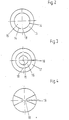
Figur 1 ein Gummilager, bei dem der Ausgleichsraum durch eine Rollmembrane begrenzt ist und bei dem die Drosselöffnung in der Bodenplatte angeordnet ist.Figuren 2 bis 6
- Figure 1 is a rubber bearing in which the compensation space is limited by a rolling membrane and in which the throttle opening is arranged in the base plate.
- Figures 2 to 6
Trennwände zur Verwendung in einem Gummilager entsprechend Figur 1.Partitions for use in a rubber bearing according to Figure 1.
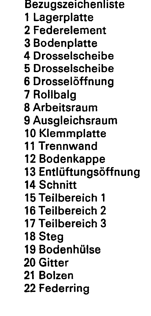
Figur 7 ein Gummilager ähnlich Figur 1, wobei die Drosselöffnung die Trennwand selbst durchdringt und wobei der Ausgleichsraum durch einen Federring begrenzt wird.Figure 7 shows a rubber bearing similar to Figure 1, wherein the throttle opening penetrates the partition itself and the compensation space is limited by a spring ring.
Figur 8 ein Gummilager, bei dem das den Arbeitsraum begrenzende Federelement und der den Ausgleichsraum begrenzende Federring durch einen die Lagerplatte und die Bodenhülse verbindenden Bolzen parallel geschaltet sind.8 shows a rubber bearing in which the spring element delimiting the working space and the spring ring delimiting the compensation space are connected in parallel by a bolt connecting the bearing plate and the base sleeve.
Das Gummilager gemäß Figur 1 besteht aus einer Bodenplatte 3, die durch das einvulkanisierte, kegelförmig ausgebildete Federelement 2 mit der Lagerplatte 1 verbunden ist. Die Bodenplatte 3 besteht aus einem tiefgezogenen Blechteil, welches im unteren Teil die Drosselscheiben 4 und 5 umschließt, einschließlich Klemmplatte 10 und der Bodenkappe 12. Die Gitteröffnungen in der Drosselscheibe 4 haben einen Durchmesser von B mm, die Gitteröffnungen in der Drosselscheibe 5 einen solchen von 12 mm. Sämtlich Teile sind durch eine Umbördelung der Bodenplatte starr verbunden.The rubber bearing according to FIG. 1 consists of a
Die Drosselscheiben 4 und 5 enthalten jeweils einen Teil des Querschnittes der spiralig ausgeführten Drosselöffnung, die den Arbeitsraum 8 und den Ausgleichsraum 9 verbindet. Durch eine gegenseitige Verdrehung der beiden Drosselscheiben 4 und 5 kann die Länge der Drosselöffnung auf ein ganz bestimmtes Maß eingestellt werden. Beide Drosselscheiben bestehen aus Zinkspritzguß und sie zeichnen sich durch eine große Maßhaltigkeit aus.The
Die Drosselscheiben enthalten im mittleren Bereich eine zylindrische Aussparung, in der die Trennwand 11 ohne ein wesentliches radiales Spiel gelagert ist. Die axiale Beweglichkeit der Trennwand wird durch Gitter 20 begrenzt. Diese haben einen gegenseitigen Abstand von 2,1 mm bei einer Dicke der Trennwand von 1,5 mm.The throttle disks contain a cylindrical recess in the central area, in which the partition 11 is mounted without any substantial radial play. The axial mobility of the partition is limited by
Der Lochdurchmesser der Trennwand beträgt bei einem Offenflächenanteil von 53 % ca. 7 mm. Die Trennwand ist oberflächlich genoppt. Sie besteht aus Weichgummi mit einer Härte Shore A von 45. Der Durchmesser beträgt 43 mm.The hole diameter of the partition is approx. 7 mm with an open area share of 53%. The partition is nubbed on the surface. It consists of soft rubber with a Shore A hardness of 45. The diameter is 43 mm.
Die Trennwand ist durch einen, parallel zum Außenumfang verlaufenden, sie senkrecht durchtrennenden Schnitt in einen innenliegenden Teilbereich 15 und einen außenliegenden Teilbereich 16 unterteilt. Der auf zwei einander gegenüberliegenden Seiten durch schmale Stege unterbrochene Schnitt 14 hat einen Durchmesser von 32 mm, woraus ein Größenverhältnis der an den Schnitt angrenzenden Flächenbereiche von 1,24 resultiert.The dividing wall is divided into an inner
Durch die Klemmplatte 10 wird ein Rollbalg 7 zugleich festgelegt und abgedichtet. Dieser besteht aus einer vorgeformten Gummifolie, die so dimensioniert ist, daß der Bodenbereich bei ruhender Belastung eine mittlere Lage einnimmt und bei extremer Ein- bzw. Ausfederung der Lagerplatte 1 die beiderseits der Mittellinie dargestellten, extremen Stellungen. Es können somit weder die Bodenkappe 12 noch die Drosselscheibe 5 von dem sich unter Betriebsbedingungen bewegenden Rollbalg 7 berührt werden.A bellows 7 is simultaneously fixed and sealed by the clamping
Die Bodenkappe 12 weist eine Entlüftungsöffnung 13 auf, durch die Luft beim Einfedern der Lagerplatte 1 entweichen kann. Der Ausgleichsraum 9 ist dadurch unter Betriebsbedingungen stets frei von Oberdrücken.The
Das dargestellte Gummilager dient der Lagerung eines Verbrennungsmotors. Dieser wird mit der Lagerplatte 1 verschraubt, das Gummilager 12 über den an der Bodenkappe 12 befindlichen Gewindebolzen mit der im Einzelfalle vorhandenen Tragkonstruktion, beispielsweise der Karosserie eines Kraftfahrzeuges.The rubber bearing shown is used to support an internal combustion engine. This is screwed to the
Bei stärkeren Motorschwingungen, wie beispielsweise durch das Oberfahren von Bodenunebenheiten verursacht, kommt es zu einer starken Ein- und Ausfederung der Lagerplatte 1, und in diesem. Zusammenhang durch ein wechselseitiges Anlegen der Trennwand an die die Bewegung beidseitig begrenzenden Gitter der Drosselscheiben 4 und 5. Das aus dem Arbeitsraum 8 verdrängte Flüssigkeitsvolumen durchströmt in diesem Falle die Drosselöffnung 6 und zunehmend die Trennwand durch den sich zu einem Spalt erweiternden Schnitt 14. Die dabei erzielte, breitbandige Dämpfungswirkung verhindert ein Aufschaukeln des Motors in sich selbst und damit die Entstehung als unangenehm empfundener Schwingungen. Es konnten weder störende Geräusche noch Kavitationserscheinungen nachgewiesen werden.With stronger engine vibrations, such as caused by driving over uneven ground, the bearing
Beim Auftreten von Motorschwingungen einer hohen Frequenz und einer kleinen Amplitude vermindert sich das die Drosselöffnung 6 und die Trennwand durch den sich verengenden Schnitt passierende Flüssigkeitsvolumen. Parallel hierzu kommt es zu einer Verminderung der Drosselwirkung und es resultiert eine zunehmende Abkopplung des schwingenden Motors von der Bodenplatte, d.h. eine gute Schwingungsisolierung. Beispielsweise Dröhnschwingungen, die bei hohen Motordrehzahlen auftreten, können nicht mehr auf die Karosserie übertragen werden. Störende Geräusche oder Kavitationserscheinungen wurden auch in diesem Falle in dem mit einer üblichen hydraulischen Flüssigkeit gefüllten Motorlager nicht beobachtet. Auch in dem Zwischenbereich zwischen den vorstehend skizzierten, extremen Betriebszuständen treten nachteilige Wirkungen nicht ein.When engine vibrations of a high frequency and a small amplitude occur, the volume of liquid passing through the
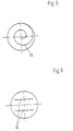
Die in einem Gummilager gemäß Figur 1 verwendete Trennwand ist in Figur 2 in der Draufsicht wiedergegeben. Der Schnitt 14 erstreckt sich parallel zum Außenumfang der Trennwand, und er ist auf einander gegenüberliegenden Seiten durch einen schmalen Steg 18 unterbrochen, dessen Breite etwa der dreifachen Dicke der Trennwand entspricht. Das Verhältnis aus der Fläche des größeren Teilbereiches 16 und des kleineren Teilbereiches 15 beträgt 1:24.The partition used in a rubber bearing according to Figure 1 is shown in Figure 2 in plan view. The
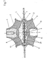
Figur 3 entspricht im wesentlichen Figur 2, wobei jedoch durch zwei konzentrisch ineinanderliegende Scnnitte eine dreifache Unterteilung in die Teilbereiche 15, 16 und 17 vorgenommen worden ist. Die einen jeden Schnitt auf einander gegenüberliegenden Seiten der Trennwand unterbrechenden Stege 18 sind den Stegen des nächstfolgenden Schnittes unter einem Winkel von 90° zugeordnet.FIG. 3 essentially corresponds to FIG. 2, but a three-fold subdivision into the sub-areas 15, 16 and 17 has been carried out by means of two concentrically arranged cuts. The
Figur 4 zeigt eine Ausführung, bei der.vier Einzelschnitte am Außenumfang beginnend in radialer Richtung nach innen erstrecken. Die Schnitte unterteilen die Trennwand in unterschiedlich große Teilbereiche.FIG. 4 shows an embodiment in which four individual cuts on the outer circumference, starting in the radial direction, extend inwards. The cuts divide the partition into sections of different sizes.
Figur 5 zeigt eine Ausführung bei der die kreisförmig begrenzte Trennwand durch einen spiralig ausgeführten Schnitt 18 in Teilbereiche einer unterschiedlichen Größe zerlegt ist, Figur 6 eine Ausführung, bei der zwei, dem selben Zwecke dienende, sich parallel zueinander erstreckende, geradlinig geführte Schnitte 18 den Umfang nicht erreichen. Auch in diesem Falle haben die beiderseits des Schnittes einander gegenüberliegenden Teilbereiche eine unterschiedliche Größe.FIG. 5 shows an embodiment in which the circularly delimited partition is divided into partial areas of different sizes by a spiral cut 18, FIG. 6 shows an embodiment in which two
Figur 7 zeigt eine Ausführung ähnlich Figur 1, wobei jedoch die Drosselöffnung 6 nicht in den Drosselscheiben 4, 5 angeordnet ist, sondern in der Trennwand 11. Sie hat eine zylindrische Gestalt und einen Durchmesser von 7 mm.Figure 7 shows an embodiment similar to Figure 1, but the
Die Trennwand ist entsprechend Figur 3 durch zwei konzentrisch ineinanderliegende Schnitte in drei verschiedene Teilbereiche 15, 16 und 17 unterteilt. Das Größenverhältnis zwischen den Teilbereichen beträgt im ersten Falle 1,4, im zweiten Falle 1,5.According to FIG. 3, the dividing wall is divided into three different sub-areas 15, 16 and 17 by two concentric cuts. The size ratio between the partial areas is 1.4 in the first case and 1.5 in the second case.
Der Ausgleichsraum 9 ist entgegen der Ausführung nach Figur 1 elastisch vorgespannt durch einen Federring 22. Dieser ist ähnlich Figur 2 ausgebildet und durch Vulkanisation mit dem Bodenteil 3 und der Bodenhülse 19 fest verbunden. Die Detailausbildung wurde auch in diesem Falle so vorgenommen, daß bei extremer Einfederung der Lagerplatte 1 bzw. der Bodenhülse 19 eine Berührung der. Drosselscheiben 4, 5 so gut wie ausgeschlossen ist.The
Figur 8 zeigt eine Ausführung ähnlich Figur 7, wobei jedoch die Bodenhülse 19 und die Lagerplatte 1 durch einen Bolzen 21 starr verbunden sind. Der Ausgleichsraum ist dadurch dem Arbeitsraum in seiner Wirkung parallel geschaltet, was eine entsprechende Ausführung besonders geeignet macht für Anwendungsfälle, in denen eine einseitig gerichtete Vorbelastung nicht vorhanden ist, wie beispielsweise bei der seitlichen Abstützung eines schwingenden Gerätes. Die Drosselöffnung wird durch den Spalt zwischen der Trennwand und dem Umfang des Bolzens 21 gebildet.
Claims (10)
Applications Claiming Priority (2)
| Application Number | Priority Date | Filing Date | Title |
|---|---|---|---|
| DE3225700A DE3225700C1 (en) | 1982-07-09 | 1982-07-09 | Elastic rubber bearing |
| DE3225700 | 1982-07-09 |
Publications (2)
| Publication Number | Publication Date |
|---|---|
| EP0098331A1 EP0098331A1 (en) | 1984-01-18 |
| EP0098331B1 true EP0098331B1 (en) | 1986-01-15 |
Family
ID=6168026
Family Applications (1)
| Application Number | Title | Priority Date | Filing Date |
|---|---|---|---|
| EP19820110747 Expired EP0098331B1 (en) | 1982-07-09 | 1982-11-20 | Elastic rubber support |
Country Status (3)
| Country | Link |
|---|---|
| US (1) | US4773634A (en) |
| EP (1) | EP0098331B1 (en) |
| DE (2) | DE3225700C1 (en) |
Cited By (1)
| Publication number | Priority date | Publication date | Assignee | Title |
|---|---|---|---|---|
| US10145443B2 (en) | 2015-01-26 | 2018-12-04 | Itt Manufacturing Enterprises Llc | Compliant elastomeric shock absorbing apparatus |
Families Citing this family (67)
| Publication number | Priority date | Publication date | Assignee | Title |
|---|---|---|---|---|
| GB8313111D0 (en) * | 1983-05-12 | 1983-06-15 | Avon Ind Polymers | Hydraulically damped mounting |
| US4595183A (en) * | 1983-03-09 | 1986-06-17 | Bridgestone Tire Company Limited | Vibration isolating device |
| DE3474272D1 (en) * | 1983-07-22 | 1988-11-03 | Honda Motor Co Ltd | Fluid-sealed engine mounting |
| US4588173A (en) * | 1983-11-23 | 1986-05-13 | General Motors Corporation | Hydraulic-elastomeric mount |
| DE3347273A1 (en) * | 1983-12-28 | 1985-07-11 | Lemförder Metallwaren AG, 2844 Lemförde | ELASTIC BEARING WITH A HYDRAULIC SHOCK ABSORBER |
| DE3347274A1 (en) * | 1983-12-28 | 1985-07-11 | Lemförder Metallwaren AG, 2844 Lemförde | HYDRAULIC VIBRATION DAMPER FOR ELASTIC SUPPORT BEARINGS IN MOTOR VEHICLES |
| US4630808A (en) * | 1983-12-28 | 1986-12-23 | Bridgestone Corporation | Vibration isolating devices |
| DE3402715A1 (en) * | 1984-01-26 | 1985-08-01 | Metzeler Kautschuk GmbH, 8000 München | TWO-CHAMBER ENGINE MOUNT WITH HYDRAULIC DAMPING |
| JPS60184737A (en) * | 1984-02-21 | 1985-09-20 | Honda Motor Co Ltd | Hydraulic mount |
| DE3407553A1 (en) * | 1984-03-01 | 1985-09-05 | Continental Gummi-Werke Ag, 3000 Hannover | HYDRAULIC DAMPED ELASTIC BEARING IN PARTICULAR FOR THE DRIVE ENGINE IN MOTOR VEHICLES |
| JPS60234144A (en) * | 1984-05-03 | 1985-11-20 | Toyoda Gosei Co Ltd | Liquid encapsulated vibro-preventive device |
| DE3418123A1 (en) * | 1984-05-16 | 1985-11-21 | Diehl GmbH & Co, 8500 Nürnberg | ELASTIC RUBBER BEARING WITH INTEGRATED HYDRAULIC DAMPING |
| JPS6145130A (en) * | 1984-08-07 | 1986-03-05 | Toyo Tire & Rubber Co Ltd | Liquid damping type vibration insulating supporting device |
| FR2575253B1 (en) * | 1984-12-24 | 1989-08-18 | Hutchinson | HYDRAULIC ANTIVIBRATORY SUPPORT |
| DE3501112C2 (en) * | 1985-01-15 | 1986-12-04 | Fa. Carl Freudenberg, 6940 Weinheim | Engine mounts |
| DE3501628A1 (en) * | 1985-01-19 | 1986-07-31 | Boge Gmbh, 5208 Eitorf | HYDRAULIC DAMPING RUBBER BEARING |
| US4641808A (en) * | 1985-02-22 | 1987-02-10 | Flower Wallace C | Dynamic vibration attenuator utilizing inertial fluid |
| DE3521246A1 (en) * | 1985-06-13 | 1987-01-02 | Kaspar Lochner | Elastic support |
| DE3522482A1 (en) | 1985-06-22 | 1987-01-15 | Freudenberg Carl Fa | HYDRAULIC DAMPING ENGINE MOUNT |
| DE3526686A1 (en) * | 1985-07-25 | 1987-02-05 | Metzeler Kautschuk | TWO-CHAMBER ENGINE MOUNT WITH HYDRAULIC DAMPING |
| US4664363A (en) * | 1985-10-07 | 1987-05-12 | General Motors Corporation | Hydraulic-elastomeric mount displacement decoupler |
| US4679777A (en) * | 1985-10-07 | 1987-07-14 | General Motors Corporation | Hydraulic-elastomeric mount displacement decoupler |
| DE3632670A1 (en) * | 1986-09-26 | 1988-04-07 | Boge Ag | HYDRAULIC DAMPING RUBBER BEARING |
| US4762308A (en) * | 1987-03-30 | 1988-08-09 | The Firestone Tire & Rubber Company | Damping valve for air spring suspension systems |
| GB2242724B (en) * | 1987-05-12 | 1992-01-22 | Honda Motor Co Ltd | Fluid filled vibroisolating device |
| US4903951A (en) * | 1987-05-12 | 1990-02-27 | Honda Giken Kogyo Kabushiki Kaisha | Fluid-filled vibroisolating device |
| FR2619179B1 (en) * | 1987-08-03 | 1989-12-22 | Hutchinson | IMPROVEMENTS ON HYDRAULIC ANTIVIBRATORY SUPPORTS |
| DE3731524A1 (en) * | 1987-09-18 | 1989-04-06 | Metzeler Gmbh | HYDRAULIC DAMPING TWO-CHAMBER ENGINE MOUNT |
| DE3737252A1 (en) * | 1987-11-03 | 1989-05-24 | Wolf Woco & Co Franz J | HYDRAULIC DAMPED ELASTOMER METAL BEARING |
| DE3739464A1 (en) * | 1987-11-21 | 1989-06-01 | Lemfoerder Metallwaren Ag | Hydraulically damped mount for motor vehicles |
| GB8730005D0 (en) * | 1987-12-23 | 1988-02-03 | Avon Ind Polymers | Hydraulically damped mounting device |
| DE3801108A1 (en) * | 1988-01-16 | 1989-07-27 | Audi Ag | Engine hydraulic bearing |
| DE3825780A1 (en) * | 1988-07-29 | 1990-02-01 | Bayerische Motoren Werke Ag | Elastic mount with hydraulic damping, especially an engine mount for motor vehicles |
| ATE104029T1 (en) * | 1989-11-09 | 1994-04-15 | Freudenberg Carl Fa | RUBBER MOUNTING WITH HYDRAULIC DAMPING. |
| DE4027808A1 (en) * | 1990-09-01 | 1992-04-30 | Boge Ag | ELASTIC RUBBER BEARING |
| US5273261A (en) * | 1992-04-17 | 1993-12-28 | General Motors Corporation | Hydraulic torque strut with decoupling and related mounting system |
| DE4435271C1 (en) * | 1994-10-01 | 1995-11-30 | Lemfoerder Metallwaren Ag | Hydraulically damped vehicle engine mount |
| US5516084A (en) * | 1995-04-14 | 1996-05-14 | General Motors Corporation | Hydraulic engine mount with diaphragm decoupler |
| DE59603462D1 (en) * | 1995-07-27 | 1999-12-02 | Lemfoerder Metallwaren Ag | Engine mounts for motor vehicles |
| ES2138503B1 (en) * | 1995-10-20 | 2001-02-16 | Btr Antivibration Syst Inc | SILENTBLOC HYDRO / ELASTIC SERIES FOR A DRIVER TRAIN. |
| DE19620976C2 (en) * | 1996-05-24 | 1998-11-19 | Freudenberg Carl Fa | Hydro bearing |
| DE19620971C2 (en) * | 1996-05-24 | 1999-02-25 | Freudenberg Carl Fa | Hydro bearing |
| US6068246A (en) * | 1998-04-28 | 2000-05-30 | General Motors Corporation | Slim profile hydraulic engine mount |
| US6056279A (en) * | 1998-04-30 | 2000-05-02 | General Motors Corporation | Duo-pumping hydraulic mount |
| DE19843558B4 (en) * | 1998-09-23 | 2004-07-22 | Zf Boge Elastmetall Gmbh | Hydraulically damping rubber bearing |
| EP1069338B1 (en) * | 1999-07-13 | 2004-08-18 | Carl Freudenberg KG | Hydraulically dampened support |
| JP3489500B2 (en) * | 1999-08-10 | 2004-01-19 | 東海ゴム工業株式会社 | Anti-vibration device |
| US6547226B2 (en) * | 2001-02-05 | 2003-04-15 | Delphi Technologies, Inc. | Bi-state hydraulic mount with annular decoupler |
| US6439556B1 (en) * | 2001-02-15 | 2002-08-27 | Delphi Technologies, Inc. | Active decoupler hydraulic mount |
| FR2828540B1 (en) | 2001-08-07 | 2003-10-31 | Hutchinson | HYDRAULIC ANTIVIBRATORY SUPPORT |
| FR2851312B1 (en) * | 2003-02-13 | 2006-06-23 | Hutchinson | HYDRAULIC ANTIVIBRATORY SUPPORT |
| JP4359889B2 (en) * | 2004-09-30 | 2009-11-11 | 東海ゴム工業株式会社 | Fluid filled vibration isolator |
| US7788808B1 (en) | 2005-02-25 | 2010-09-07 | Lord Corporation | Method of making an equipment engine mounting system |
| JP4383426B2 (en) * | 2006-05-08 | 2009-12-16 | 本田技研工業株式会社 | Power unit support device for vehicle |
| DE102007007857B4 (en) * | 2007-02-16 | 2012-03-29 | Trelleborg Automotive Germany Gmbh | Hydraulically damping bearing |
| JP5210558B2 (en) * | 2007-07-12 | 2013-06-12 | 株式会社ブリヂストン | Vibration isolator |
| EP2435269B1 (en) * | 2009-05-26 | 2017-08-16 | Trelleborg Corporation | Main rubber element for hydraulic engine mounts |
| JP5940877B2 (en) * | 2012-04-27 | 2016-06-29 | 山下ゴム株式会社 | Liquid seal vibration isolator |
| JP6072242B2 (en) * | 2013-06-03 | 2017-02-01 | 株式会社ブリヂストン | Vibration isolator |
| EP3088766B1 (en) | 2014-02-17 | 2018-04-11 | Bridgestone Corporation | Vibration-damping device |
| JP6391186B2 (en) * | 2014-08-20 | 2018-09-19 | 株式会社ブリヂストン | Vibration isolator and method for suppressing generation of abnormal noise caused by cavitation collapse |
| US10001191B2 (en) | 2015-01-16 | 2018-06-19 | Ford Global Technologies, Llc | Pneumatically tuned vehicle powertrain mounts |
| JP6674334B2 (en) * | 2016-06-23 | 2020-04-01 | 株式会社ブリヂストン | Anti-vibration device |
| EP3770463A4 (en) * | 2018-05-10 | 2021-12-29 | Bridgestone Corporation | Vibration damping device |
| JP2020139546A (en) * | 2019-02-27 | 2020-09-03 | 本田技研工業株式会社 | Variable rigidity vibration control device |
| JP2020139547A (en) * | 2019-02-27 | 2020-09-03 | 本田技研工業株式会社 | Movable rigidity vibration control device |
| KR20200142181A (en) * | 2019-06-12 | 2020-12-22 | 현대자동차주식회사 | Fluid-sealed engine mount |
Family Cites Families (14)
| Publication number | Priority date | Publication date | Assignee | Title |
|---|---|---|---|---|
| FR1112598A (en) * | 1954-10-16 | 1956-03-15 | Variable section hydraulic damper piston with oil passage | |
| FR1132284A (en) * | 1955-09-26 | 1957-03-07 | Renault | Refinements to valves |
| US2941544A (en) * | 1955-09-27 | 1960-06-21 | Renault | Fluid control devices and elastic pressure-responsive valves |
| US3245426A (en) * | 1962-11-13 | 1966-04-12 | Robertshaw Controls Co | Pneumatic selector relay |
| US3490488A (en) * | 1968-02-27 | 1970-01-20 | Jacobs Mfg Co | Elastic exhaust cap |
| US3811466A (en) * | 1972-04-06 | 1974-05-21 | J Ohringer | Slit diaphragm valve |
| US4045009A (en) * | 1975-11-17 | 1977-08-30 | General Motors Corporation | Energy absorbing unit with improved control valve |
| DE2727244C2 (en) * | 1976-06-30 | 1990-06-21 | Automobiles Peugeot, 75116 Paris | Rubber spring with liquid filling |
| DE2823720C2 (en) * | 1978-05-31 | 1983-04-07 | Boge Gmbh, 5208 Eitorf | Two-chamber engine mounts with hydraulic damping, in particular for motor vehicles |
| EP0006819B1 (en) * | 1978-07-03 | 1984-06-27 | Automobiles Peugeot | Suspension device in particular for a vehicle engine |
| US4416445A (en) * | 1978-10-13 | 1983-11-22 | Imperial Clevite Inc. | Viscous spring damper |
| FR2467724A1 (en) * | 1979-10-22 | 1981-04-30 | Peugeot | ELASTIC BODY, IN PARTICULAR FOR THE SUSPENSION OF A MOTOR VEHICLE |
| DE3019337C2 (en) * | 1980-05-21 | 1986-07-31 | Fa. Carl Freudenberg, 6940 Weinheim | Elastic rubber mount |
| DE3019377A1 (en) * | 1980-05-21 | 1981-11-26 | LuK Lamellen und Kupplungsbau GmbH, 7580 Bühl | DEVICE FOR STARTING AN INTERNAL COMBUSTION ENGINE |
-
1982
- 1982-07-09 DE DE3225700A patent/DE3225700C1/en not_active Expired
- 1982-11-20 EP EP19820110747 patent/EP0098331B1/en not_active Expired
- 1982-11-20 DE DE8282110747T patent/DE3268604D1/en not_active Expired
-
1987
- 1987-12-21 US US07/139,157 patent/US4773634A/en not_active Expired - Lifetime
Cited By (2)
| Publication number | Priority date | Publication date | Assignee | Title |
|---|---|---|---|---|
| US10145443B2 (en) | 2015-01-26 | 2018-12-04 | Itt Manufacturing Enterprises Llc | Compliant elastomeric shock absorbing apparatus |
| US11078983B2 (en) | 2015-01-26 | 2021-08-03 | Itt Manufacturing Enterprises Llc | Compliant elastomeric shock absorbing apparatus |
Also Published As
| Publication number | Publication date |
|---|---|
| EP0098331A1 (en) | 1984-01-18 |
| DE3268604D1 (en) | 1986-02-27 |
| DE3225700C1 (en) | 1983-11-17 |
| US4773634A (en) | 1988-09-27 |
Similar Documents
| Publication | Publication Date | Title |
|---|---|---|
| EP0098331B1 (en) | Elastic rubber support | |
| EP0098330B1 (en) | Elastic rubber support | |
| EP0426940B1 (en) | Rubber support with hydraulic damping | |
| DE2802896C2 (en) | Rubber mounts with hydraulic damping | |
| DE102012005991B4 (en) | Liquid-filled anti-vibration device | |
| EP0040290B2 (en) | Elastic rubber mount | |
| EP0205657B2 (en) | Hydraulically damped engine support | |
| DE102004059406B4 (en) | With a fluid-filled vibration damping device | |
| EP0209883B1 (en) | Hydraulically damped engine mount having two chambers | |
| DE3816445C2 (en) | ||
| DE3821240C2 (en) | ||
| DE19843558B4 (en) | Hydraulically damping rubber bearing | |
| DE10037954A1 (en) | Hydro bearing | |
| EP0534124B1 (en) | Elastic engine support | |
| DE69930446T2 (en) | Liquid-sealed, elastic storage | |
| DE3940004C2 (en) | ||
| DE69824135T2 (en) | Vibration-damping device with liquid chambers on opposite sides of a partition structure with movable rubber plate | |
| DE102004001322B4 (en) | Acoustic decoupled hydro bearing | |
| DE10203208A1 (en) | Vibration damping device with an independent mass element | |
| EP0415001B1 (en) | Hydraulic support | |
| EP0161554A2 (en) | Elastic rubber mount with integral hydraulic damping | |
| EP0512195B1 (en) | Engine mounting with adjustable elasticity level | |
| EP1347200B1 (en) | Hydraulic bearing | |
| EP0307693A2 (en) | Hydraulically damping two-chamber engine mounting | |
| DE112019003332T5 (en) | FLUID-FILLED VIBRATION DAMPING DEVICE |
Legal Events
| Date | Code | Title | Description |
|---|---|---|---|
| PUAI | Public reference made under article 153(3) epc to a published international application that has entered the european phase |
Free format text: ORIGINAL CODE: 0009012 |
|
| 17P | Request for examination filed |
Effective date: 19831031 |
|
| AK | Designated contracting states |
Designated state(s): DE FR GB IT |
|
| GRAA | (expected) grant |
Free format text: ORIGINAL CODE: 0009210 |
|
| ITF | It: translation for a ep patent filed |
Owner name: BARZANO' E ZANARDO ROMA S.P.A. |
|
| AK | Designated contracting states |
Designated state(s): DE FR GB IT |
|
| REF | Corresponds to: |
Ref document number: 3268604 Country of ref document: DE Date of ref document: 19860227 |
|
| ET | Fr: translation filed | ||
| R20 | Corrections of a patent specification |
Effective date: 19860407 |
|
| PLBE | No opposition filed within time limit |
Free format text: ORIGINAL CODE: 0009261 |
|
| STAA | Information on the status of an ep patent application or granted ep patent |
Free format text: STATUS: NO OPPOSITION FILED WITHIN TIME LIMIT |
|
| 26N | No opposition filed | ||
| ITTA | It: last paid annual fee | ||
| PGFP | Annual fee paid to national office [announced via postgrant information from national office to epo] |
Ref country code: GB Payment date: 20011022 Year of fee payment: 20 |
|
| PGFP | Annual fee paid to national office [announced via postgrant information from national office to epo] |
Ref country code: DE Payment date: 20011107 Year of fee payment: 20 |
|
| PGFP | Annual fee paid to national office [announced via postgrant information from national office to epo] |
Ref country code: FR Payment date: 20011122 Year of fee payment: 20 |
|
| REG | Reference to a national code |
Ref country code: GB Ref legal event code: IF02 |
|
| PG25 | Lapsed in a contracting state [announced via postgrant information from national office to epo] |
Ref country code: GB Free format text: LAPSE BECAUSE OF EXPIRATION OF PROTECTION Effective date: 20021119 |
|
| REG | Reference to a national code |
Ref country code: GB Ref legal event code: PE20 Effective date: 20021119 |