EP0040271B1 - Improvements in and relating to composite tapes and apparatus for winding composite tape - Google Patents
Improvements in and relating to composite tapes and apparatus for winding composite tape Download PDFInfo
- Publication number
- EP0040271B1 EP0040271B1 EP80301627A EP80301627A EP0040271B1 EP 0040271 B1 EP0040271 B1 EP 0040271B1 EP 80301627 A EP80301627 A EP 80301627A EP 80301627 A EP80301627 A EP 80301627A EP 0040271 B1 EP0040271 B1 EP 0040271B1
- Authority
- EP
- European Patent Office
- Prior art keywords
- tape
- roller
- foil
- insulating tape
- composite
- Prior art date
- Legal status (The legal status is an assumption and is not a legal conclusion. Google has not performed a legal analysis and makes no representation as to the accuracy of the status listed.)
- Expired
Links
Images


Classifications
-
- H—ELECTRICITY
- H01—ELECTRIC ELEMENTS
- H01B—CABLES; CONDUCTORS; INSULATORS; SELECTION OF MATERIALS FOR THEIR CONDUCTIVE, INSULATING OR DIELECTRIC PROPERTIES
- H01B13/00—Apparatus or processes specially adapted for manufacturing conductors or cables
- H01B13/06—Insulating conductors or cables
- H01B13/10—Insulating conductors or cables by longitudinal lapping
-
- B—PERFORMING OPERATIONS; TRANSPORTING
- B65—CONVEYING; PACKING; STORING; HANDLING THIN OR FILAMENTARY MATERIAL
- B65H—HANDLING THIN OR FILAMENTARY MATERIAL, e.g. SHEETS, WEBS, CABLES
- B65H39/00—Associating, collating, or gathering articles or webs
- B65H39/16—Associating two or more webs
Abstract
Description
- This invention concerns composite tapes and apparatus for forming composite tapes and in particular relates to apparatus for forming an insulated electrostatic screen for use in electrical coils, e.g. for use in the winding of transformers and the like.
- It is known to provide electrostatic screens in coil winding, the screen serving the dual purpose of insulating one winding from another and also providing an electrostatic screen to prevent unwanted spurious transfer from one winding to another in a transformer. Whilst the winding of the wire to form a coil has been a rapid process the interleaving of one winding with another by an electrostatic insulating screen has often introduced considerable delays into the process of coil winding particularly where the insulating material and metal foil has had to be interleaved by hand.
- It is obviously imperative that the metal foil is fully insulated from both windings and also from itself so that an electrical short circuit does not occur and further delays have been experienced in the past while insulation tests have been carried out prior to continuing winding.
- DE-A-2542018 concerns the manufacture of electric cables in which a laminated ribbon is wound round a cable core in a longitudinal direction, with an outer plastics casing extruded around the core and surrounding ribbon. The laminated ribbon is formed by thermally fusing a metal band and a broader plastics band, and then physically turning up and over one or both protruding edge strips of the plastics band.
- BE-A-754150 concerns the production of cable in which a series of conductors are sandwiched between two flexible strips, one of which has an inwardly facing self-adhesive layer.
- It is an object of the present invention to provide apparatus for forming an insulating electrostatic screen for electrical coils which can be wound directly around a coil during manufacture and which will have reliable insulating properties.
- It is another object to provide an improved composite tape.
- According to the present invention there is provided apparatus for forming composite tape, comprising first roller storage means of metal or metallised foil, second roller storage means of plastics insulating tape which is wider than the width of the foil, first roller means around which both the foil and the plastics insulating tape can be passed with the foil sandwiched between the roller and the insulating tape and located centrally of the tape, second roller means beyond the first roller means which progressively cause the free edges of the insulating tape on either side of the foil to be turned upwardly and over the foil as it passes through the second roller means, characterised in that the composite tape is insulated electrostatic screen for electrical coils, with the insulating tape being approximately twice the width of the foil, the apparatus further comprising third roller storage means having wound thereon self-adhesive plastics insulating tape, third roller means below which the self-adhesive insulating tape is passed with the self-adhesive surface away from the roller for urging the adhesive surface into contact with the two folded-over edges of the plastics insulating tape to cause the self-adhesive tape to adhere thereto, fourth roller means between which the composite tape is passed for exerting pressure on opposite sides of the composite tape to ensure good adhesion between the adhesive tape and the plastics insulating tape, first braking means associated with the first roller storage means to resist rotation thereof and maintain a degree of tension in the foil, and second braking means associated with the second roller storage means to resist rotation thereof and maintain a degree of tension in the insulating tape.
- Preferably two or more roller storage means are provided for the plastics insulating tape to allow one, two or more thicknesses of insulating tape to be employed.
- Preferably the width of the plastics insulating tape is just less than twice the width of the metal foil around which it is to be wrapped so that a gap exists between the turned-over edges of the plastics insulating tape along the length of the composite tape so that the self-adhesive surface of the plastics tape which is applied to the turned-over edges makes contact with the exposed surface of the metal foil to more securely anchor the latter in the composite tape.
- Means may be provided for adjusting the pressure between the rollers forming the said fourth roller means to compensate for different thicknesses of composite tape.
- Preferably means is provided for altering or replacing the rollers of the said third roller means to accommodate different widths of insulating tape.
- Preferably means is provided for each of the storage means to resist rotation of the storage means to a slight degree to maintain tension in the tapes and foil. Preferably the braking means so employed is adjustable to increase or decrease the tension so imparted to the tape or foil.
- The fourth roller means may be adjustable to accommodate different widths of composite tape.
- Preferably the self-adhesive plastics tape is self-coloured and preferably a different colour is used to denote a different standard of manufacture of the composite tape. Thus where a double thickness of insulating tape material has been used one colour self-adhesive tape may be employed and where only a single layer of insulating plastics tape has been used to form the outer sleeve, another colour of self-adhesive plastics tape may be employed.
- The apparatus can be incorporated directly into a coil winding machine so that the formed composite tape is simply pulled from the fourth roller means as and when required and wound around the coil on the machine. To this end the invention also provides a coil winding machine when fitted with apparatus embodying the invention.
- Alternatively the apparatus may include a coil-winding bobbin and drive means for preparing bobbins of composite insulating electrostatic screen which can then be stored on the bobbin either for subsequent use or for sale.
- The invention also includes within its scope composite tape when formed by apparatus embodying the invention.
- The invention will now be described by way of example with reference to the accompanying drawings in which:-
- Figure 1 is a perspective view of apparatus embodying the invention,
- Figure 2 is an exploded perspective view of the apparatus shown in Figure 1,
- Figure 3 is a perspective view of the apparatus of Figure 1 when fitted with storage drums of the various component tapes to make the composite insulating electrostatic screen with the various component tapes threaded through the apparatus to indicate the mode of operation of the apparatus,
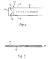
- Figure 4 is a plan view of an insulated metal foil screen for use in the winding of transformers and the like with the various component parts peeled away one from the other at the left-hand end of the screen, and
- Figure 5 is a cross-section through the tape shown in Figure 4 at the line II-II drawn to an enlarged scale.
- Referring to Figure 1 the apparatus comprises a
base 10 having anupstanding support flange 12 for carrying various drum storage devices to be described hereinafter. I - In line with the
support flange 12 is provided achannel support 14 forming the exit for the apparatus through which the formed screen tape is passed and for housing rollers (to be described later) for performing the final forming operation of the composite screen tape. - The base includes
fixing holes 16 by which the apparatus can be clamped to a bench or to a coil-winding machine or the like. - As described hitherto the apparatus is self- sufficient in that tape can be pulled directly from the exit at 18 or the apparatus can be combined with a coil-winding machine to allow the screen tape to be pulled form the exit as and when required and wound directly on a coil bobbin or it can be combined with a coil-winding bobbin and drive means for winding bobbins of the insulating electrostatic screen for storing the screen material in bulk either for subsequent use or for sale.
- Referring again to Figure 1, two
spindles flange 12 and includebacking discs spindles - A take-
off roller 28 is mounted on afurther spindle 30 which extends from theflange 12 and around which the insulating tape from spools mounted on thespindles - It should be explained at this point that the two
spindles spindles roller 28. - A reel of metallised foil typically copper tape is mounted on a
third spindle 32 which also extends from theflange 12 and includes abacking disc 34. Again the reel of metallised foil is preferably mounted on thespindle 32 so that there is a small resistance to rotation on the spindle so as to impart a slight tension to the copper tape as it is pulled therefrom. In practice the resistance to the removal of the copper tape should only be small since the metal tape will not stretch in the same way as will the Melinex. - The metal tape passes around a
further roller 36 carried on aspindle 38 which also extends from and is supported by theflange 12. The metal tape is trapped between theroller 36 and the layer or layers of Melinex tape from theroller 28.Further rollers spindles rollers - This is best seen with reference to Figure 3 in which two reels of Melinex tape at 48 and 50 supply two layers of
tape further reel 56 contains copper foil as shown at 58 which passes around theroller 36 and is trapped between the roller and the two layers of Melinextape - The width of the
copper foil 58 is approximately half the width of the Melinex tape and as the now composite tape passes between the flanges ofrollers - Reverting to Figure 1, a
fourth spindle 60 is mounted on theflange 12 again with abacking disc 62 for carrying a reel of self-adhesive tape not shown in Figure 1. The reel is shown in Figure 3 at 64 and the tape is removed as shown at 66 with the adhesive surface on the underside. Thetape 66 passes underneath aroller 68 carried in the channel support means 14 and is thereby brought into contact with the turned-over edges of the Melinex tape presented to the underside of theroller 68 by means of anotherroller 70 also located between the sides of thechannel support 14. Bothrollers - The composite tape then passes over a
block 72 and under afinal exit roller 74 forming an exit nip. - Referring to Figure 2 it will be seen that the
exit roller 74 is mounted on aspindle 76 which can readily be removed from thechannel support 14 by removing thepin 78 and withdrawing thespindle 76 using theknurled end 80. In this way theroller 74 can be removed to allow the composite tape to be threaded over thebase 72 and theroller 74 replaced so as to exert the required pressure on the tape. - It will be seen that the
channel section 14 can be removed from thebase 10 by removing the twoscrews 82 and can be replaced with a different channel section with different rollers to accommodate different tape sizes or thechannel section 14 may be formed from two parts which can be set at different spacings to accommodate different widths of composite tape. - As shown in Figure 4 an insulated metal foil screen for use in the winding of transformers and the like comprises a
metal foil 110 typically of copper foil some few thousandths of an inch thick, a first strip ofplastics tape 112 the width of which is just less than twice the width of thefoil 110 and a second strip or tape of semi-opaqueplastics sheet material 114 which is adhesively bonded to thefirst plastics tape 112 and to thefoil 110. - The foil is almost totally enclosed within a sleeve formed by the
first plastics tape 112 and to this end thefoil 110 is located midway across the width of thetape 112 and the two opposite edges of the tape are folded up and over thefoil 110 so as to overlie the upper surface thereof. In Figure 4 the extreme left-hand end of the strip ortape 114 is shown peeled away from the two in-turnededges tape 112 and these in-turnededges foil 110 with the restraining influence of thetape 114 removed. - The tape or
strip 114 is self-adhesive plastics tape and for convenience is self-coloured rendering the tape opaque or semi-opaque. - The two turned-in edges of the
tape 112 do not meet but present a gap through which theadhesive tape 114 can adhere to thefoil 110 to locate the latter in position. - Preferred materials are copper foil for the
screen 110, Melinex tape for thesleeve 112 and PVC self-adhesive tape for thestrip 114.
Claims (9)
Priority Applications (3)
| Application Number | Priority Date | Filing Date | Title |
|---|---|---|---|
| EP80301627A EP0040271B1 (en) | 1980-05-19 | 1980-05-19 | Improvements in and relating to composite tapes and apparatus for winding composite tape |
| DE8080301627T DE3069493D1 (en) | 1980-05-19 | 1980-05-19 | Improvements in and relating to composite tapes and apparatus for winding composite tape |
| AT80301627T ATE9982T1 (en) | 1980-05-19 | 1980-05-19 | COMPOSITE TAPES AND APPARATUS FOR REWINDING COMPOSITE TAPES. |
Applications Claiming Priority (1)
| Application Number | Priority Date | Filing Date | Title |
|---|---|---|---|
| EP80301627A EP0040271B1 (en) | 1980-05-19 | 1980-05-19 | Improvements in and relating to composite tapes and apparatus for winding composite tape |
Publications (2)
| Publication Number | Publication Date |
|---|---|
| EP0040271A1 EP0040271A1 (en) | 1981-11-25 |
| EP0040271B1 true EP0040271B1 (en) | 1984-10-24 |
Family
ID=8187166
Family Applications (1)
| Application Number | Title | Priority Date | Filing Date |
|---|---|---|---|
| EP80301627A Expired EP0040271B1 (en) | 1980-05-19 | 1980-05-19 | Improvements in and relating to composite tapes and apparatus for winding composite tape |
Country Status (3)
| Country | Link |
|---|---|
| EP (1) | EP0040271B1 (en) |
| AT (1) | ATE9982T1 (en) |
| DE (1) | DE3069493D1 (en) |
Cited By (1)
| Publication number | Priority date | Publication date | Assignee | Title |
|---|---|---|---|---|
| CN104319022A (en) * | 2013-02-07 | 2015-01-28 | 滁州华尊电气科技有限公司 | System used for manufacturing aluminum plastic composite belt with adhesive layers of continuous distribution and adopting gas pressure source |
Families Citing this family (1)
| Publication number | Priority date | Publication date | Assignee | Title |
|---|---|---|---|---|
| CN105858290A (en) * | 2016-05-09 | 2016-08-17 | 北京中科海讯数字科技股份有限公司 | Automatic double-layer tape wrapping device |
Family Cites Families (5)
| Publication number | Priority date | Publication date | Assignee | Title |
|---|---|---|---|---|
| BE754150A (en) * | 1970-07-30 | 1970-12-31 | Leroli S A | IMPROVEMENTS TO FLAT CABLES WITH MULTIPLE CONDUCTORS AND EQUIPMENT TO MANUFACTURE THEM, |
| US3989561A (en) * | 1973-11-23 | 1976-11-02 | General Motors Corporation | Method of applying a laminated insulating film to copper wire |
| DE2542018C3 (en) * | 1975-09-20 | 1981-08-06 | The Fujikura Cable Works, Ltd., Tokyo | Method of manufacturing a sheathed electrical cable |
| SE398570B (en) * | 1976-04-26 | 1977-12-27 | Asea Ab | METHOD OF APPLYING A BAND OF INSULATION MATERIAL IN THE LENGTH DIRECTION OF A MAINLY RECTANGULAR ELECTRICAL CONDUCTOR AND DEVICE FOR PERFORMING THE KIT |
| DE2845909C2 (en) * | 1978-10-21 | 1985-11-28 | Hans Kolbe & Co, 3202 Bad Salzdetfurth | Method for manufacturing a ribbon cable |
-
1980
- 1980-05-19 EP EP80301627A patent/EP0040271B1/en not_active Expired
- 1980-05-19 DE DE8080301627T patent/DE3069493D1/en not_active Expired
- 1980-05-19 AT AT80301627T patent/ATE9982T1/en not_active IP Right Cessation
Cited By (2)
| Publication number | Priority date | Publication date | Assignee | Title |
|---|---|---|---|---|
| CN104319022A (en) * | 2013-02-07 | 2015-01-28 | 滁州华尊电气科技有限公司 | System used for manufacturing aluminum plastic composite belt with adhesive layers of continuous distribution and adopting gas pressure source |
| CN104319022B (en) * | 2013-02-07 | 2016-11-23 | 滁州华尊电气科技有限公司 | Manufacture the system of the aluminium-plastic tape for being coated with cable cable core of adhesive-layer continuous distribution |
Also Published As
| Publication number | Publication date |
|---|---|
| ATE9982T1 (en) | 1984-11-15 |
| EP0040271A1 (en) | 1981-11-25 |
| DE3069493D1 (en) | 1984-11-29 |
Similar Documents
| Publication | Publication Date | Title |
|---|---|---|
| CA1200538A (en) | Packaged tape for electrical conductors | |
| US4737598A (en) | Shielding tape for electrical conductors | |
| US4197348A (en) | Wrapped elongated structure in which positioning of a one sided adhesive tape is such as to permit wrapping to move relative to a core | |
| US4645549A (en) | Composite tapes and apparatus for winding composite tapes | |
| EP0040271B1 (en) | Improvements in and relating to composite tapes and apparatus for winding composite tape | |
| DE2616001C2 (en) | Leader tape for a magnetic recording tape | |
| US3037852A (en) | Method of producing abrasive rolls and sheets | |
| US2275858A (en) | Taping device | |
| US3905096A (en) | Method of fabricating coils | |
| US3378626A (en) | Method and product for shielding windings | |
| JPS5919458B2 (en) | Transformer winding formed as layered winding | |
| EP0150685A2 (en) | Method and machine for insulating electric conductors for transformers by glueing insulation coating sheet and conductors thus insulated | |
| IE49809B1 (en) | Apparatus for forming insulated electrostatic screen | |
| US3617421A (en) | Device for folding insulating tape about electrical conductors | |
| US3404050A (en) | Method and apparatus for producing insulated electrical conductors | |
| US3887851A (en) | Tension speed control for a rotatable strand supply utilizing a transformer having variable primary and secondary windings | |
| GB2065062A (en) | Wrapped elongated structure | |
| US6935396B2 (en) | Splicing tape application device with rigid electrostatic charge eliminator | |
| US3362866A (en) | Machine for making laminated tape | |
| JPS58132912A (en) | Manufacture of winding core for stationary electric apparatus | |
| US2941129A (en) | Electrical coil | |
| US1047720A (en) | Apparatus for making coils. | |
| US1047899A (en) | Coil-former. | |
| US2617609A (en) | Device for packaging and dispensing ribbons, tapes, bindings, and the like | |
| JP2003045239A (en) | Horizontal coil |
Legal Events
| Date | Code | Title | Description |
|---|---|---|---|
| PUAI | Public reference made under article 153(3) epc to a published international application that has entered the european phase |
Free format text: ORIGINAL CODE: 0009012 |
|
| AK | Designated contracting states |
Designated state(s): AT BE CH DE FR IT LU NL SE |
|
| 17P | Request for examination filed |
Effective date: 19811120 |
|
| ITF | It: translation for a ep patent filed |
Owner name: STUDIO INGG. FISCHETTI & WEBER |
|
| GRAA | (expected) grant |
Free format text: ORIGINAL CODE: 0009210 |
|
| AK | Designated contracting states |
Designated state(s): AT BE CH DE FR IT LI LU NL SE |
|
| REF | Corresponds to: |
Ref document number: 9982 Country of ref document: AT Date of ref document: 19841115 Kind code of ref document: T |
|
| REF | Corresponds to: |
Ref document number: 3069493 Country of ref document: DE Date of ref document: 19841129 |
|
| ET | Fr: translation filed | ||
| PG25 | Lapsed in a contracting state [announced via postgrant information from national office to epo] |
Ref country code: LU Free format text: LAPSE BECAUSE OF NON-PAYMENT OF DUE FEES Effective date: 19850531 |
|
| PLBE | No opposition filed within time limit |
Free format text: ORIGINAL CODE: 0009261 |
|
| STAA | Information on the status of an ep patent application or granted ep patent |
Free format text: STATUS: NO OPPOSITION FILED WITHIN TIME LIMIT |
|
| 26N | No opposition filed | ||
| PGFP | Annual fee paid to national office [announced via postgrant information from national office to epo] |
Ref country code: AT Payment date: 19860530 Year of fee payment: 7 |
|
| PG25 | Lapsed in a contracting state [announced via postgrant information from national office to epo] |
Ref country code: AT Effective date: 19890519 |
|
| PG25 | Lapsed in a contracting state [announced via postgrant information from national office to epo] |
Ref country code: SE Effective date: 19890520 |
|
| PG25 | Lapsed in a contracting state [announced via postgrant information from national office to epo] |
Ref country code: LI Effective date: 19890531 Ref country code: CH Effective date: 19890531 Ref country code: BE Effective date: 19890531 |
|
| REG | Reference to a national code |
Ref country code: CH Ref legal event code: PL |
|
| PGFP | Annual fee paid to national office [announced via postgrant information from national office to epo] |
Ref country code: NL Payment date: 19900531 Year of fee payment: 11 |
|
| PGFP | Annual fee paid to national office [announced via postgrant information from national office to epo] |
Ref country code: FR Payment date: 19910529 Year of fee payment: 12 |
|
| PGFP | Annual fee paid to national office [announced via postgrant information from national office to epo] |
Ref country code: DE Payment date: 19910611 Year of fee payment: 12 |
|
| PG25 | Lapsed in a contracting state [announced via postgrant information from national office to epo] |
Ref country code: NL Effective date: 19911201 |
|
| NLV4 | Nl: lapsed or anulled due to non-payment of the annual fee | ||
| PG25 | Lapsed in a contracting state [announced via postgrant information from national office to epo] |
Ref country code: FR Effective date: 19930129 |
|
| PG25 | Lapsed in a contracting state [announced via postgrant information from national office to epo] |
Ref country code: DE Effective date: 19930202 |
|
| REG | Reference to a national code |
Ref country code: FR Ref legal event code: ST |
|
| EUG | Se: european patent has lapsed |
Ref document number: 80301627.8 Effective date: 19900412 |