EP0150685A2 - Method and machine for insulating electric conductors for transformers by glueing insulation coating sheet and conductors thus insulated - Google Patents
Method and machine for insulating electric conductors for transformers by glueing insulation coating sheet and conductors thus insulated Download PDFInfo
- Publication number
- EP0150685A2 EP0150685A2 EP84830155A EP84830155A EP0150685A2 EP 0150685 A2 EP0150685 A2 EP 0150685A2 EP 84830155 A EP84830155 A EP 84830155A EP 84830155 A EP84830155 A EP 84830155A EP 0150685 A2 EP0150685 A2 EP 0150685A2
- Authority
- EP
- European Patent Office
- Prior art keywords
- conductor
- envelopping
- strap
- tape
- insulated
- Prior art date
- Legal status (The legal status is an assumption and is not a legal conclusion. Google has not performed a legal analysis and makes no representation as to the accuracy of the status listed.)
- Withdrawn
Links
Images


Classifications
-
- H—ELECTRICITY
- H01—ELECTRIC ELEMENTS
- H01B—CABLES; CONDUCTORS; INSULATORS; SELECTION OF MATERIALS FOR THEIR CONDUCTIVE, INSULATING OR DIELECTRIC PROPERTIES
- H01B13/00—Apparatus or processes specially adapted for manufacturing conductors or cables
- H01B13/06—Insulating conductors or cables
- H01B13/10—Insulating conductors or cables by longitudinal lapping
- H01B13/106—Insulating conductors or cables by longitudinal lapping the conductor having a rectangular cross-section
-
- H—ELECTRICITY
- H01—ELECTRIC ELEMENTS
- H01F—MAGNETS; INDUCTANCES; TRANSFORMERS; SELECTION OF MATERIALS FOR THEIR MAGNETIC PROPERTIES
- H01F41/00—Apparatus or processes specially adapted for manufacturing or assembling magnets, inductances or transformers; Apparatus or processes specially adapted for manufacturing materials characterised by their magnetic properties
- H01F41/02—Apparatus or processes specially adapted for manufacturing or assembling magnets, inductances or transformers; Apparatus or processes specially adapted for manufacturing materials characterised by their magnetic properties for manufacturing cores, coils, or magnets
- H01F41/04—Apparatus or processes specially adapted for manufacturing or assembling magnets, inductances or transformers; Apparatus or processes specially adapted for manufacturing materials characterised by their magnetic properties for manufacturing cores, coils, or magnets for manufacturing coils
- H01F41/12—Insulating of windings
- H01F41/122—Insulating between turns or between winding layers
Definitions
- the present invention relates to a method and machine for insulating electric conductors for transformers by glueing insulation coating sheet, and conductors thus insulated.
- the invention is particularly suitable for use in continuous insulating of conductors by coating with one or more glued insulating sheets, especially of strap type for both dry and oil transformers.
- insulation of electric conductors generally aluminium or copper straps, for producing dry and oil transformers has always been carried out by lapping helically the conductor with an insulating material tape very thin in thickness (0.025-0.05 mm) in one or more coating layers in the same direction or in opposite direction, alternate or not.
- the tapes of insulating sheet used are kraft paper or aramide paper, cotton fabric or fiber glass or polyester fibers, and also enameling. Coating with tape or sheet according to the above-mentioned prior art was carried out without glueing but simply by adhesion. Recent improvements have shown that insulation by glueing coating sheet on the underlying surface improves considerably insulating yield and effectiveness, see for example Italian Patent Application No.
- the invention as claimed is intended to provide a remedy to the above-mentioned disadvantages. It solves the problem by coating the conductor by means of glueing with side envelopping of a continuous longitudinal sheet.
- the present invention consists in a machine suitable for realizing a coating insulating tape glued longitudinally with laterlal envelopping on a strap conductor (40, Fig. 13).
- the machine comprises a set of operative units placed in line in rational succession which include at least: - a support for feeding coil (1) of bare strap conductor (12); - a roller straightener unit (2); - opposite roller advancing means (3); - a lower coil feeder (unwinder) (4) of insulating paper tape (12); - a smearing device (5) of glue coming from the feeding tank (6) on the upper surface of the insulating paper tape (16), placed downstream the feeding-unwinding device of the insulating tape (4); - a roller pressing device (7) for pressing wider the strap conductor (12) said insulating tape (16) with simultaneous glueing on the lower surface of said conductor (12) due to the preceding glue smearing (5); - a set of envelopping device (8) for envelopping the lateral edges of the tape (16) advancing continuously.
- the glue smearing device (5) includes also the tape feeding device (4) with an insulating tape idle coil (16) suitably braked with adjustable braking means of adjustable plate type clutch (20) axially movable (19) in order to center the position of the insulating tape (16) with respect to the strap to be coated (12) and comprising downstream two lower transmission rollers (15) between which upwards a glue smearing roller presses, (13) by means of the supporting and glue feeding arm (14) of the glue coming from the tank (6). (Figs. 3, 4).
- a roller pressing device (7) comprising a smoothing runner (17) placed under the advancing strap conductor (12), ending with a guiding roller arm (22) and including on the conductor (12) a set of idle pressing rollers (18) supported by a plate (17) with adjustable spring risers (21) for pressing and glueing the tape smeared with glue (16) against the lower surface of the conductor (12) (Figs. 5, 6).
- the set of envelopping devices (8) for envelopping the tape (16) around the strap conductor (12) comprises a sequence of belts (25,28,31,33) longitudinally stretched by an hooking upstream spring (24), placed under the conductor (12) and the coating tape (16) in horizontal flat position, and hooked downstream after partially envelopping the conductor to be coated (12) with the tape (16), transversally movable, on a respective stretching and orientable bar, placed over the conductor (12), the first bar (26) being horizontal for envelopping from a first lateral base corner,
- the second bar (26') being vertical for the remaining envelopping of the same edge on the corresponding upper corner;
- the third bar (32) being horizontal for envelopping from the other opposite base corner;
- the fourth bar (32') being vertical for the final envelopping on the corresponding upper corner with superimposition on the preceding edge already envelopped on the upper face of the conductor (12), a lateral pressing roller (27) for adhering glueing the tape on the corresponding lateral surface of the conductor (12) being provided between the envelopping of the first belt (25) and the envelopping of the second belt (28), and analougously an upper pressing roller (30) with a lower counterroller (29) being provided between the envelopping of the second belt (28) and the envelopping of the third belt (31).
- a final pressing device (9) is situated with opposite rollers (43, 35) on all four faces of the conductor already coated (40).
- a smoothing runner device (10) is placed comprising a base runner (37) and an upper runner (38) pressed by springs (36), a lower idle bearing roller (39) is provided thereafter for guiding the finished insulated conductor (40) in coiling into the rewinding coil (11).
Abstract
Method and machine for producing electric strap conductors for carrying out transformers in general, by glueing to the conductor an insulating tape in longitudinal direction instead of helical direction. The conductor thus obtained has improved characteristics and can be produced at lower cost.
Description
- The present invention relates to a method and machine for insulating electric conductors for transformers by glueing insulation coating sheet, and conductors thus insulated.
- The invention is particularly suitable for use in continuous insulating of conductors by coating with one or more glued insulating sheets, especially of strap type for both dry and oil transformers.
- At the present state of the art, insulation of electric conductors, generally aluminium or copper straps, for producing dry and oil transformers has always been carried out by lapping helically the conductor with an insulating material tape very thin in thickness (0.025-0.05 mm) in one or more coating layers in the same direction or in opposite direction, alternate or not. The tapes of insulating sheet used are kraft paper or aramide paper, cotton fabric or fiber glass or polyester fibers, and also enameling. Coating with tape or sheet according to the above-mentioned prior art was carried out without glueing but simply by adhesion. Recent improvements have shown that insulation by glueing coating sheet on the underlying surface improves considerably insulating yield and effectiveness, see for example Italian Patent Application No. 22172 A/80 filed on May 19, 1980 in the name of Paolo Zanettin, Trezzano Sul Naviglio (Milan) entitled "Electric conductor coated with adhesive and wound with insulating tape", which describes the advantages obtained by using glued tape which is wound on the conductor by helical winding method well known to those skilled in the art. Winding machines are also known for winding helically insulating tape on bar in order to obtain insulation and are of two types:
- - a first type utilizes an equipment which comprises rotation of tape rolls and simultaneous advance of same for helical winding around the bar to be insulated;
- - a second type utilizes rotation of advancing bar while winding tapes unwind in a fixed position;
- - another solution causes the bar to pass inside the roll of a winding tape and while said bar is advanced, the tape roll is rotated determining the desired winding still helically but with feed of the coating sheet inside the tape. All these solutions can provide either applying a tape without glueing or by previous smearing glue on the coating surface as known to those skilled in the art (e.g. glue sprayer) or applying self-adhesive insulating tape.
- The drawbacks of the currently used solutions and of the above-mentioned prior art consist essentially in that these machines are complex and expensive and when the resulting product, involving helical winding coating, has to be bent, said coating is very likely to detach from the underlying surface thus reducing insulating effect.
- The invention as claimed is intended to provide a remedy to the above-mentioned disadvantages. It solves the problem by coating the conductor by means of glueing with side envelopping of a continuous longitudinal sheet.
- The advantages offered by this invention are mainly that insulation is extremely quicker and less expensive. Moreover, the result of insulation is much more effective.
- One way of carrying out the invention is described in detail below with reference to drawings which illustrate some preferred embodiments, in which:
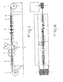
- Figure 1 is a schematic side elevation view of the machine for treating conductors according to the present invention; Figure 2 is a plan view of the machine of the preceding figure; Figures 3-4 are scrap views of the machine of the preceding figures enlarged respectively in side elevation view and in plan view of the unit relating to the glue smearer on the coating-insulating tape;
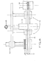
- Figures 5-6 are scrap view of the machine of Figures 1,2 enlarged respectively in side elevation and plan views of the opposite rollers pressure unit relating to the pressing-glueing step of the insulating tape on the lower surface of the strap conductor;
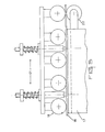
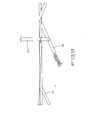
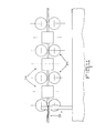
- Figures 7, 8 and 9 are plan enlarged scrap views of the machine of figures 1,2 relating the units respectively: the first one to the lateral envelopping bend and the remaining envelopping upper edge with successive glueing lateral and upper pressing respectively of the tape on a corresponding lateral and upper surface, the second lateral envelopping bend on the corresponding lateral surface opposed to the preceding one, and finally the third envelopping bend on the upper side corresponding on the same upper surface in overlapping; Figures 10, 11 and 13 show in the same scrap enlarged plan and side elevation view the final pressing step for complete the adhesion-glueing of the insulating sheet by means of opposite rollers and smooting devices to abtain the final product Fig.13.
- According to the above figures the present invention consists in a machine suitable for realizing a coating insulating tape glued longitudinally with laterlal envelopping on a strap conductor (40, Fig. 13).
- The machine comprises a set of operative units placed in line in rational succession which include at least: - a support for feeding coil (1) of bare strap conductor (12); - a roller straightener unit (2); - opposite roller advancing means (3); - a lower coil feeder (unwinder) (4) of insulating paper tape (12); - a smearing device (5) of glue coming from the feeding tank (6) on the upper surface of the insulating paper tape (16), placed downstream the feeding-unwinding device of the insulating tape (4); - a roller pressing device (7) for pressing wider the strap conductor (12) said insulating tape (16) with simultaneous glueing on the lower surface of said conductor (12) due to the preceding glue smearing (5); - a set of envelopping device (8) for envelopping the lateral edges of the tape (16) advancing continuously. with the strap conductor (12) for envelopping first one edge and then the other one superimposing the first one around the strap conductor (12); - an opposite roller pressing unit on the four sides for completing the glueing by compression with final rolling of adhesion and glueing of the coating thus envelopped (16) on the strap of bar conductor (12); - a smoothing runner device in sliding material for smoothing the surfaces of the conductor thus insulated (40) removing possible air bubbles or harmful wrinklings; - a coil rewinding device (11) of the conductor thus insulated (40). In the glueing system it is very important that excess glue did not get out of the coating edges causing possible glueing between turns during rewinding.
- More in detail, the glue smearing device (5) includes also the tape feeding device (4) with an insulating tape idle coil (16) suitably braked with adjustable braking means of adjustable plate type clutch (20) axially movable (19) in order to center the position of the insulating tape (16) with respect to the strap to be coated (12) and comprising downstream two lower transmission rollers (15) between which upwards a glue smearing roller presses, (13) by means of the supporting and glue feeding arm (14) of the glue coming from the tank (6). (Figs. 3, 4).
- Downstream the glue feeding device (5) a roller pressing device (7) is provided comprising a smoothing runner (17) placed under the advancing strap conductor (12), ending with a guiding roller arm (22) and including on the conductor (12) a set of idle pressing rollers (18) supported by a plate (17) with adjustable spring risers (21) for pressing and glueing the tape smeared with glue (16) against the lower surface of the conductor (12) (Figs. 5, 6).
- The set of envelopping devices (8) for envelopping the tape (16) around the strap conductor (12) comprises a sequence of belts (25,28,31,33) longitudinally stretched by an hooking upstream spring (24), placed under the conductor (12) and the coating tape (16) in horizontal flat position, and hooked downstream after partially envelopping the conductor to be coated (12) with the tape (16), transversally movable, on a respective stretching and orientable bar, placed over the conductor (12), the first bar (26) being horizontal for envelopping from a first lateral base corner,
- the second bar (26') being vertical for the remaining envelopping of the same edge on the corresponding upper corner; the third bar (32) being horizontal for envelopping from the other opposite base corner; the fourth bar (32') being vertical for the final envelopping on the corresponding upper corner with superimposition on the preceding edge already envelopped on the upper face of the conductor (12), a lateral pressing roller (27) for adhering glueing the tape on the corresponding lateral surface of the conductor (12) being provided between the envelopping of the first belt (25) and the envelopping of the second belt (28), and analougously an upper pressing roller (30) with a lower counterroller (29) being provided between the envelopping of the second belt (28) and the envelopping of the third belt (31).
- After the last belt (33) a final pressing device (9) is situated with opposite rollers (43, 35) on all four faces of the conductor already coated (40).
- Downstream the pressing roller device (9) a smoothing runner device (10) is placed comprising a base runner (37) and an upper runner (38) pressed by springs (36), a lower idle bearing roller (39) is provided thereafter for guiding the finished insulated conductor (40) in coiling into the rewinding coil (11).
- In the illustrated embodiment smearing of room temperature setting glue is provided, but it is obvious that also a hot-setting glue can be used, but in this case a more complex machine is required as heating devices have Lo be provided for drying glue getting out of the envelopping.
- Of course, changes and modifications can be made without departing from the spirit or scope of the invention as defined in the appended claims. Udine, June, 1984.
Claims (11)
1. Method for producing electric insulated conductors by coating the conductor with one or more glued insulating sheets, particularly of strap type for carrying out transformers, characterised in that it comprises:
- continuous feeding by advancing meeens (3) of a bare strap conductor (12) on a working line from a coil (1);
- straightening said bare strap (12) on said continuous line (2);
- feeding under said strap (12) a continuous insulating material tape (16) with adhesive upper surface (5), wider than said conductor strap (12) and larger in width than the length of the perimeter development of the section of said strap (12);
- glueing centrally approx (7) said continuous insulating tape (16) under and with said conductor strap (12) making same to advance together;
- envelopping at an envelopping unit (8) first an edge (25, 28) and than the other (31, 33) of the said insulating tape and making them to adhere around the strap conductor for coating thereof in superimposition glued on the top;
- pressing the coating applied for making it to adhere glued (9, 10);
rewinding the insulated conductor (40) on a coil (11).2. Machine for carrying out the method as claimed in claim 1, characterised in that it consists in a set of operative units placed in line in rational sequence, said units comprising at least:
- a support (1) for nude conductor bare strap conductor coil (12);
- a roller straightening unit (2);
- an opposite roller conveying conductor advancing device (3);
- a lower feeding coil (4) of insulating tape (12);
- a roller pressing device (7) for pressing under the strap conductor (12) said insulating tape (16) with simultaneous glueing on the lower surface of said conductor (12) due to the previous glue smearing (5);
- a ser of envelopping devices (8) for envelopping the lateral edges of the tape (16) advancing continuously with the strap conductor (12) to envelop first one edge and then the other one superimposing to the first around the strap conductor (12);
- a pressing unit with opposite rollers on the four sides for sopping compression with final rolling of adhesion and glueing of the coating thus envelopped (16) on the bare strap conductor (12);
- a smoothing device in sliding material for smoothing the surfaces of the conductor thus insulated (40) removing possible air bubbles or harmful wrinklings;
- a coil rewinding device (11) of the conductor thus insulated (40).
3. A machine as claimed in claims 1 and 2, characterised in that a glue smearing device (5) is installed on the upper surface of the insulated paper tape (16) between said insulating tape feeding device (4) and said glueing device (17, 8).
4. A machine as claimed in the preceding claims, characterised in that said glue smearing device (5) comprises also said tape feeding device (4) with an idle insulated tape coil (16) conveniently braked by adjustable breaking means of adjustable plate type clutch (20) and axially movable (19) for centering the insulated tape position (16) with respect to the strap to be coated (12) and provided downstream with two mower transmission rollers (15) between which a glue smearing roller (13) presses upwards, by means of the supporting and glue feeding arm (14) of the glue coming from the tank (6).
5. A machine as claimed in the preceding claims, characterised in that said roller pressing device (7) for glueing the insulated tape (16) under the surface of the bare conductor (12) comprises a smoothing runner (17) placed under the advancing strap conductor
(12), ending with a guiding roller arm (22) and provided on said conductor (12) with a set of idle pressing rollers (18) supported by a plate (17) provided with adjustable spring risers (21) for pressing and glueing the tape smeared with glue (16) against the lower surface of the conductor (12).
6. A machine as claimed in the preceding claims, characterised in that said set: of envelopping devices (8) for envelopping the tape (16) around the strap conductor (12) comprises a sequence of belts (25, 28, 31, 33) longitudinally strechted by an upstream spring (24), placed upstream hooked in horizontal flat position under the conductor (12) and coating tape (16), and downstream hooked after partially envelopping the conductor to be coated (12) with the insulating tape (16), in transversally adjustable hooking position on a respective stretching and orienting bar, placed over the conductor (12), respectively:
- the first bar (26) being horizontal for envelopping from a first lateral base corner;
- the second bar (26') being vertical for the remaining envelopping of the same edge on the corresponding upper corner;
- the third bar (32) being horizontal for envelopping from the other opposite base corner;
- the fourth bar (32') being vertical for the final envelopping on the corresponding upper corner superimposing the preceding edge already envelopped on the upper face of the conductor (12);
- at least one respective lateral pressing roller (27) for adhesion glueing of the tape on the corresponding lateral surface of the conductor (12) being provided between the envelopping of the first belt (25) and the envelopping of the second belt (28), and analogously at least one respective upper pressing roller being provided between the envelopping of the second belt (28) and the envelopping of the third one (31).
7. A machine as claimed in the preceding claims, characterised in that after the last belt (33) a final pressing device (9) is placed with opposite rollers (43, 35) on all four faces of the conductor already coated (40).
8. A machine as claimed in the preceding claims, characterised in that downstream the final pressing roller device (9) the smoothing device (10) is placed comprising a base smooting (37) and an upper smooting (38) pressed by spring (36).
9. A machine as claimed in the preceding claims, characterised in that at the end of the coating and smoothing treatment (10) an idle support lower roller (39) is provided for guiding the finished insulated conductor (40) coiling in a rewinding coil (11).
10. Insulated conductor obtained by means of the method as claimed in claim 1 and/or by means of a machine as claimed in claims 2 to 9, characterised in that said insulated conductor comprises a metallic strap electric conductor (12) longitudinally coated by glueing with at least one insulating tape in lengthwise direction and with opposed lateral transversally envelopping with with respective overlapping in one of his surfaces. Udine, June, 1984.
Applications Claiming Priority (2)
| Application Number | Priority Date | Filing Date | Title |
|---|---|---|---|
| IT41522/84A IT1199513B (en) | 1984-02-01 | 1984-02-01 | MACHINE WITH WHICH ELECTRICAL CONDUCTORS ARE INSULATED FOR THE CONSTRUCTION OF TRANSFORMERS IN GENERAL, APPLYING TO THE CONDUCTOR AN INSULATING TAPE IN THE LONGITUDINAL SENSE, EVEN IN THE HELICAL SENSE |
| IT4152284 | 1984-02-01 |
Publications (2)
| Publication Number | Publication Date |
|---|---|
| EP0150685A2 true EP0150685A2 (en) | 1985-08-07 |
| EP0150685A3 EP0150685A3 (en) | 1987-05-06 |
Family
ID=11250592
Family Applications (1)
| Application Number | Title | Priority Date | Filing Date |
|---|---|---|---|
| EP84830155A Withdrawn EP0150685A3 (en) | 1984-02-01 | 1984-05-21 | Method and machine for insulating electric conductors for transformers by glueing insulation coating sheet and conductors thus insulated |
Country Status (2)
| Country | Link |
|---|---|
| EP (1) | EP0150685A3 (en) |
| IT (1) | IT1199513B (en) |
Cited By (9)
| Publication number | Priority date | Publication date | Assignee | Title |
|---|---|---|---|---|
| EP0545370A1 (en) * | 1991-12-02 | 1993-06-09 | Sterling Paper Corporation | Insulated magnet wire, method of forming the same, and insulation therefor |
| WO2003105301A1 (en) * | 2002-06-05 | 2003-12-18 | Bbi Electric S.P.A. | Method for wrapping bus-bars for prefabricated electric ducts |
| WO2004057665A2 (en) * | 2002-12-20 | 2004-07-08 | Bbi Electric S.P.A. | Process and system for manufacturing prefabricated electrical conductors |
| CN103466364A (en) * | 2013-09-16 | 2013-12-25 | 苏州工业园区格米克精密机械有限公司 | Taping and winding machine for winding and packaging roll materials |
| CN103646782A (en) * | 2013-11-28 | 2014-03-19 | 国网河南省电力公司鹤壁供电公司 | Transformer coil end insulator manufacturing device |
| CN105097257A (en) * | 2014-05-16 | 2015-11-25 | 中国科学院沈阳自动化研究所 | Automatic production line for insulation oil passage of transformer |
| US10090084B1 (en) | 2018-02-12 | 2018-10-02 | Travis J. Cronkrite | Modular bus bar insulator |
| CN110444349A (en) * | 2019-09-18 | 2019-11-12 | 嘉兴田然贸易有限公司 | A kind of winding machine for special cable line |
| CN112691860A (en) * | 2020-12-09 | 2021-04-23 | 苏州砺宏电子设备有限公司 | Inductance spraying processing equipment |
Citations (5)
| Publication number | Priority date | Publication date | Assignee | Title |
|---|---|---|---|---|
| FR871678A (en) * | 1940-04-25 | 1942-05-05 | Felten & Guilleaume Carlswerk | Method and device for insulating electrical conductors |
| US2989430A (en) * | 1959-02-11 | 1961-06-20 | Plastic Wire & Cable Corp | Core wrapping apparatus |
| FR2025820A1 (en) * | 1968-12-10 | 1970-09-11 | Emile Haefely Sa Ets | |
| US3902938A (en) * | 1972-03-02 | 1975-09-02 | Ford Motor Co | Process for continuously covering a linear element |
| FR2349933A1 (en) * | 1976-04-26 | 1977-11-25 | Asea Ab | METHOD AND DEVICE FOR APPLYING A TAPE OF INSULATING MATERIAL IN THE LONGITUDINAL DIRECTION OF AN ESSENTIALLY RECTANGULAR ELECTRIC CONDUCTOR. |
-
1984
- 1984-02-01 IT IT41522/84A patent/IT1199513B/en active
- 1984-05-21 EP EP84830155A patent/EP0150685A3/en not_active Withdrawn
Patent Citations (5)
| Publication number | Priority date | Publication date | Assignee | Title |
|---|---|---|---|---|
| FR871678A (en) * | 1940-04-25 | 1942-05-05 | Felten & Guilleaume Carlswerk | Method and device for insulating electrical conductors |
| US2989430A (en) * | 1959-02-11 | 1961-06-20 | Plastic Wire & Cable Corp | Core wrapping apparatus |
| FR2025820A1 (en) * | 1968-12-10 | 1970-09-11 | Emile Haefely Sa Ets | |
| US3902938A (en) * | 1972-03-02 | 1975-09-02 | Ford Motor Co | Process for continuously covering a linear element |
| FR2349933A1 (en) * | 1976-04-26 | 1977-11-25 | Asea Ab | METHOD AND DEVICE FOR APPLYING A TAPE OF INSULATING MATERIAL IN THE LONGITUDINAL DIRECTION OF AN ESSENTIALLY RECTANGULAR ELECTRIC CONDUCTOR. |
Cited By (16)
| Publication number | Priority date | Publication date | Assignee | Title |
|---|---|---|---|---|
| EP0545370A1 (en) * | 1991-12-02 | 1993-06-09 | Sterling Paper Corporation | Insulated magnet wire, method of forming the same, and insulation therefor |
| WO2003105301A1 (en) * | 2002-06-05 | 2003-12-18 | Bbi Electric S.P.A. | Method for wrapping bus-bars for prefabricated electric ducts |
| CN100438246C (en) * | 2002-06-05 | 2008-11-26 | Bbi电气有限公司 | Method for wrapping bus-bars for prefabricated electric ducts |
| WO2004057665A2 (en) * | 2002-12-20 | 2004-07-08 | Bbi Electric S.P.A. | Process and system for manufacturing prefabricated electrical conductors |
| WO2004057665A3 (en) * | 2002-12-20 | 2004-08-12 | Bbi Electric Spa | Process and system for manufacturing prefabricated electrical conductors |
| CN100351955C (en) * | 2002-12-20 | 2007-11-28 | Bbi电气有限公司 | Process and system for manufacturing prefabricated electrical conductors |
| CN103466364A (en) * | 2013-09-16 | 2013-12-25 | 苏州工业园区格米克精密机械有限公司 | Taping and winding machine for winding and packaging roll materials |
| CN103646782B (en) * | 2013-11-28 | 2016-08-17 | 国网河南省电力公司鹤壁供电公司 | Transformer coil end insulation preparation facilities |
| CN103646782A (en) * | 2013-11-28 | 2014-03-19 | 国网河南省电力公司鹤壁供电公司 | Transformer coil end insulator manufacturing device |
| CN105097257A (en) * | 2014-05-16 | 2015-11-25 | 中国科学院沈阳自动化研究所 | Automatic production line for insulation oil passage of transformer |
| CN105097257B (en) * | 2014-05-16 | 2017-01-25 | 中国科学院沈阳自动化研究所 | Automatic production line for insulation oil passage of transformer |
| US10090084B1 (en) | 2018-02-12 | 2018-10-02 | Travis J. Cronkrite | Modular bus bar insulator |
| US10373743B1 (en) | 2018-02-12 | 2019-08-06 | Travis James Cronkrite | Modular bus bar insulator |
| US10796825B1 (en) | 2018-02-12 | 2020-10-06 | Travis James Cronkrite | Modular bus bar insulator |
| CN110444349A (en) * | 2019-09-18 | 2019-11-12 | 嘉兴田然贸易有限公司 | A kind of winding machine for special cable line |
| CN112691860A (en) * | 2020-12-09 | 2021-04-23 | 苏州砺宏电子设备有限公司 | Inductance spraying processing equipment |
Also Published As
| Publication number | Publication date |
|---|---|
| EP0150685A3 (en) | 1987-05-06 |
| IT8441522A0 (en) | 1984-02-01 |
| IT1199513B (en) | 1988-12-30 |
| IT8441522A1 (en) | 1985-08-01 |
Similar Documents
| Publication | Publication Date | Title |
|---|---|---|
| US4729814A (en) | Apparatus for making an offset laminated roofing shingle | |
| US2627645A (en) | Method of manufacturing condensers | |
| WO1986000282A1 (en) | Apparatus and method for cutting and spooling a web of paper | |
| EP0150685A2 (en) | Method and machine for insulating electric conductors for transformers by glueing insulation coating sheet and conductors thus insulated | |
| US2402038A (en) | Wood tubing manufacture | |
| US2954816A (en) | Apparatus and method for reinforcing sheet material | |
| US4434948A (en) | Apparatus for producing overlapping band rolls from superposed overlapping flat workpieces | |
| US5861071A (en) | Electrically insulated magnet wire and method of making the same | |
| US3037852A (en) | Method of producing abrasive rolls and sheets | |
| US4070214A (en) | Process for continuous precision lamination of multiple strips to a substrate | |
| RU2301765C2 (en) | Labeling method and apparatus | |
| US3796621A (en) | Method of fabricating a laminate and product thereof | |
| EP0362460A3 (en) | Method and apparatus for making electrical heater pad | |
| EP0151501A2 (en) | Method and device for arranging a wire-shaped element in a given pattern between layers of material or webs of material | |
| JPH084166Y2 (en) | Multi-strand metal band tensioning device | |
| DE3710639C2 (en) | ||
| CN211279795U (en) | Side overflow prevention adhesive tape production device for packaging paper production | |
| WO2005108050A1 (en) | Strap and methods for producing strap | |
| CN218707568U (en) | Full-automatic deviation-rectifying synchronous surface unreeling machine | |
| CN215096257U (en) | Be applied to and shell membrane device and laminating machine on laminating machine | |
| CA2125729A1 (en) | Continuous Film Feed Device and Method Therefor | |
| EP0040271A1 (en) | Improvements in and relating to composite tapes and apparatus for winding composite tape | |
| JPS6246257Y2 (en) | ||
| DE935375C (en) | High-voltage cable with insulation made of insulating strips, preferably paper strips, in particular with oil filling for nominal voltages above 200kV | |
| JP2000506824A (en) | Method for winding webs, especially paper or paperboard webs |
Legal Events
| Date | Code | Title | Description |
|---|---|---|---|
| PUAI | Public reference made under article 153(3) epc to a published international application that has entered the european phase |
Free format text: ORIGINAL CODE: 0009012 |
|
| AK | Designated contracting states |
Designated state(s): AT BE CH DE FR GB LI LU NL SE |
|
| PUAL | Search report despatched |
Free format text: ORIGINAL CODE: 0009013 |
|
| AK | Designated contracting states |
Kind code of ref document: A3 Designated state(s): AT BE CH DE FR GB LI LU NL SE |
|
| STAA | Information on the status of an ep patent application or granted ep patent |
Free format text: STATUS: THE APPLICATION IS DEEMED TO BE WITHDRAWN |
|
| 18D | Application deemed to be withdrawn |
Effective date: 19871107 |
|
| RIN1 | Information on inventor provided before grant (corrected) |
Inventor name: PALMARIN, TADDEO |