EP0040133A2 - Filteranordnung mit einer auswechselbaren Filterpatrone - Google Patents
Filteranordnung mit einer auswechselbaren Filterpatrone Download PDFInfo
- Publication number
- EP0040133A2 EP0040133A2 EP81400692A EP81400692A EP0040133A2 EP 0040133 A2 EP0040133 A2 EP 0040133A2 EP 81400692 A EP81400692 A EP 81400692A EP 81400692 A EP81400692 A EP 81400692A EP 0040133 A2 EP0040133 A2 EP 0040133A2
- Authority
- EP
- European Patent Office
- Prior art keywords
- cannister
- filter assembly
- filter
- jaw elements
- assembly
- Prior art date
- Legal status (The legal status is an assumption and is not a legal conclusion. Google has not performed a legal analysis and makes no representation as to the accuracy of the status listed.)
- Withdrawn
Links
- 230000000694 effects Effects 0.000 claims abstract description 3
- 230000006835 compression Effects 0.000 claims description 3
- 238000007906 compression Methods 0.000 claims description 3
- 230000000063 preceeding effect Effects 0.000 claims 1
- 241000283216 Phocidae Species 0.000 description 2
- 230000000712 assembly Effects 0.000 description 2
- 238000000429 assembly Methods 0.000 description 2
- 241000283118 Halichoerus grypus Species 0.000 description 1
- 239000004809 Teflon Substances 0.000 description 1
- 229920006362 Teflon® Polymers 0.000 description 1
- 239000011248 coating agent Substances 0.000 description 1
- 238000000576 coating method Methods 0.000 description 1
- 238000010276 construction Methods 0.000 description 1
- 239000012530 fluid Substances 0.000 description 1
- 238000009434 installation Methods 0.000 description 1
- 238000012423 maintenance Methods 0.000 description 1
- 230000014759 maintenance of location Effects 0.000 description 1
- 239000000463 material Substances 0.000 description 1
- 230000000737 periodic effect Effects 0.000 description 1
- 230000000717 retained effect Effects 0.000 description 1
Images

Classifications
-
- B—PERFORMING OPERATIONS; TRANSPORTING
- B01—PHYSICAL OR CHEMICAL PROCESSES OR APPARATUS IN GENERAL
- B01D—SEPARATION
- B01D35/00—Filtering devices having features not specifically covered by groups B01D24/00 - B01D33/00, or for applications not specifically covered by groups B01D24/00 - B01D33/00; Auxiliary devices for filtration; Filter housing constructions
- B01D35/30—Filter housing constructions
-
- B—PERFORMING OPERATIONS; TRANSPORTING
- B01—PHYSICAL OR CHEMICAL PROCESSES OR APPARATUS IN GENERAL
- B01D—SEPARATION
- B01D2201/00—Details relating to filtering apparatus
- B01D2201/30—Filter housing constructions
- B01D2201/301—Details of removable closures, lids, caps, filter heads
Definitions
- This invention relates to replaceable cartridge filter assemblies and relates especially but not exclusively to replaceable oil filter assemblies for vehicle engine.
- either the filter cannister as well as the enclosed filter element is disposeable and replaceable at periodic maintenance times or alternatively, the filter element is contained within a cannister which is retained as a permanent part of the installation and only the filter element itself is replaced.
- One such assembly is disclosed in United States Patent No. 3,490,594 and reference to that Specification enables one to observe that special tools are required to remove the cannister from a base structure for replacement purposes.
- the present invention seeks to provide an oil filter assembly in.which the filter cannister may be quickly and easily removed from the base assembly by a vehicle operator without the use of specialised tools.
- a filter assembly with a replaceable filter element in an open-ended filter cannister, the open end of which is slideable over and sealable with a projecting part of a base structure of the assembly to enclose the filter element, characterised by the base structure carrying a purality of jaw elements spaced around the said projecting part, said jaw elements being concommictantly laterally displaceable by a rotary actuator member adapted to effect a cam action in relation to said members and thereby enable them to retain or release the cannister.
- the filter assembly 10 includes .a generally cylindrical cannister 12 which is closed at the upper end and open at the lower end, the lower end being provided with a rolled shoulder 14 for mounting over a generally cylindrical projecting part 16 of a base structure to enclose a replaceable filter element 17 within the cannister.
- the part 16 includes a pair of inlet passages 18 and 20 of which only the inlet passage 20 is visible in the view of Fig. 1 which is provided in the drawing.
- the part 16 also includes an outlet passage 22.
- the surface 23 of the projecting part 16 co-operates with the filter elements 17 so that oil flowing from inlets 18 and 20 to outlet 22 must pass through the filter element 17.
- the part 16 includes a large diameter portion 24 separated from a smaller diameter portion 26 by a flange 28.
- An annular groove 30 in the portion 24 provides for the retention of an 0-ring 32 which provides a.seal between the open end of the cannister 12 and the base part 16.
- Six equally spaced radial bores 34 are provided for receiving press-fitted guide pins 36 which extends radially into the base part 16.
- Three mounting bores 38 also extend axially to the base part 16.
- Three equally spaced mounting bolts 40 are also provided as shown extending through the mounting bores 38 to bolt the part 16 to a supporting member 42, the member 42 being suitably provided with tap threads for this purpose.
- Support member 42 maybe either fixed to or a part of a vehicle engine block which is not shown and it is provided with a pair of inlets 46 of which only one is visible in Fig. 1 but which communicates oil from the engine block to the filter element 17 via inlet passages 18 and 20.
- An outlet passage 48 communicates oil from the filter element 17 back to the engine block via the base outlet passage 22.
- Filter element 17 is of generally known construction and such that fluid entering via inlets 18 and 20 passes through the filter 17 in order to reach the outlet 22.
- the supporting member 42 also includes a pair of annular slots 50 and 52 which contain 0-ring seals 54 and 56 which prevent oil leakage from between the support member 42 and the base member 16.
- Support member 42 also includes a partially threaded axially bore 58 which houses a ball 60 urged upwardly by a spring 62 compressed by an adjustable screw 64.
- the ball 60 engages with a recess 74 to hold the ring 70 locked against such movement as might occur as a result of vibration.
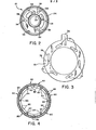
- the annular cam ring 70 rests against the supporting member 42 and is coaxially rotatable around the smaller diameter portion 26 of the base part 16.
- Six equally spaced oblong cam slots 72 extend axially through the cam ring 70 as clearly seen in Fig. 3 where the identations 74 and 76 and a manually accessible actuating tab 78 are also clearly visible.
- each jaw element 80 fits coaxially and end to end around the base diameter 16, each jaw element 80 including a base portion 82 with.an axial for 84 which receives a press fitted cam-pin 86. These cam pins 86 are slideably received by the above mentioned cam slots 72 of the cam ring 70.
- Each jaw element 80 also includes an axial bore 90 which slideably receives a corresponding one of guide pins 36.
- a downward facing abutment surface 92 of each jaw element is provided to co-operate with the shoulder 14 of the cannister 12 to positively prevent the removal of the cannister 12 from the projecting part 16 when the jaw elements 80 are in an inwardly , disposed position.
- a suitable bearing material such as "Teflon” maybe used as a coating on the sliding surfaces of 42, 16, 70 and jaw elements 80.
- the cannister In operation of the filter assembly as described above, the cannister is mounted to the assembly by pressing it downwards over the projecting part 16 until the shoulder 14 thereof moves pass the surfaces 92 on the underside of the engaging portion 88 of the jaw elements 80. The cannister 12 may then be locked to the assembly by rotating the cam ring 70 by means of the tab 78 in a clock-wise direction viewed in the direction of para.
- the cam ring 70 When it is desired to replace the filter element 17 , the cam ring 70 is rotated in an anti-clockwise direction viewed in the direction of the arrow A, to drive the cam pins 86 and jaw elements 80 radially outwards towards a position such as shown by draughtsmen licence on the right hand side of Fig. 1. In this position, the detent 76 receives the ball 60 and the cam ring is held in a position whereby the portions 88 of the jaw elements 80 are sufficiently separated from the cylindrical cannister to permit the latter to be removed from the base plant 16 and replacement of the filter element can thereby be achieved without the use of special tools to remove the cannister.
Applications Claiming Priority (2)
| Application Number | Priority Date | Filing Date | Title |
|---|---|---|---|
| US14797980A | 1980-05-08 | 1980-05-08 | |
| US147979 | 1980-05-08 |
Publications (2)
| Publication Number | Publication Date |
|---|---|
| EP0040133A2 true EP0040133A2 (de) | 1981-11-18 |
| EP0040133A3 EP0040133A3 (de) | 1982-04-21 |
Family
ID=22523718
Family Applications (1)
| Application Number | Title | Priority Date | Filing Date |
|---|---|---|---|
| EP81400692A Withdrawn EP0040133A3 (de) | 1980-05-08 | 1981-04-30 | Filteranordnung mit einer auswechselbaren Filterpatrone |
Country Status (4)
| Country | Link |
|---|---|
| EP (1) | EP0040133A3 (de) |
| JP (1) | JPS574207A (de) |
| AU (1) | AU7006381A (de) |
| CA (1) | CA1164810A (de) |
Cited By (5)
| Publication number | Priority date | Publication date | Assignee | Title |
|---|---|---|---|---|
| EP0442365A2 (de) * | 1990-02-14 | 1991-08-21 | Stanadyne Automotive Corp. | Schlüsselsystem fÀ¼r Filteranlage |
| USD492753S1 (en) | 2003-04-25 | 2004-07-06 | Procter & Gamble | Fluidic cartridge end piece |
| USD494654S1 (en) | 2003-04-25 | 2004-08-17 | Procter & Gamble Co. | Fluidic cartridge fittings |
| US10525387B2 (en) | 2017-04-06 | 2020-01-07 | Whirlpool Corporation | Filter cartridge |
| US10584040B2 (en) | 2017-10-06 | 2020-03-10 | Whirlpool Corporation | Filter cartridge |
Families Citing this family (1)
| Publication number | Priority date | Publication date | Assignee | Title |
|---|---|---|---|---|
| US4764275A (en) * | 1985-10-25 | 1988-08-16 | Robichaud Arthur W | Fluid filter and method for attaching same in sealing relation to a filter mount |
Citations (3)
| Publication number | Priority date | Publication date | Assignee | Title |
|---|---|---|---|---|
| DE939062C (de) * | 1952-10-01 | 1956-02-16 | Paul Forkardt K G | Vorderendfutter |
| US2780470A (en) * | 1953-12-01 | 1957-02-05 | Emi Ltd | Chucks |
| US3490594A (en) * | 1968-11-21 | 1970-01-20 | Fram Corp | Filter |
-
1981
- 1981-01-27 CA CA000369461A patent/CA1164810A/en not_active Expired
- 1981-04-30 EP EP81400692A patent/EP0040133A3/de not_active Withdrawn
- 1981-05-01 AU AU70063/81A patent/AU7006381A/en not_active Abandoned
- 1981-05-08 JP JP6841581A patent/JPS574207A/ja active Pending
Patent Citations (3)
| Publication number | Priority date | Publication date | Assignee | Title |
|---|---|---|---|---|
| DE939062C (de) * | 1952-10-01 | 1956-02-16 | Paul Forkardt K G | Vorderendfutter |
| US2780470A (en) * | 1953-12-01 | 1957-02-05 | Emi Ltd | Chucks |
| US3490594A (en) * | 1968-11-21 | 1970-01-20 | Fram Corp | Filter |
Cited By (7)
| Publication number | Priority date | Publication date | Assignee | Title |
|---|---|---|---|---|
| EP0442365A2 (de) * | 1990-02-14 | 1991-08-21 | Stanadyne Automotive Corp. | Schlüsselsystem fÀ¼r Filteranlage |
| EP0442365A3 (en) * | 1990-02-14 | 1991-10-23 | Stanadyne Automotive Corp. | Key system for filter assembly |
| USD492753S1 (en) | 2003-04-25 | 2004-07-06 | Procter & Gamble | Fluidic cartridge end piece |
| USD494654S1 (en) | 2003-04-25 | 2004-08-17 | Procter & Gamble Co. | Fluidic cartridge fittings |
| US10525387B2 (en) | 2017-04-06 | 2020-01-07 | Whirlpool Corporation | Filter cartridge |
| US10967313B2 (en) | 2017-04-06 | 2021-04-06 | Whirlpool Corporation | Filter cartridge |
| US10584040B2 (en) | 2017-10-06 | 2020-03-10 | Whirlpool Corporation | Filter cartridge |
Also Published As
| Publication number | Publication date |
|---|---|
| AU7006381A (en) | 1981-11-12 |
| CA1164810A (en) | 1984-04-03 |
| EP0040133A3 (de) | 1982-04-21 |
| JPS574207A (en) | 1982-01-09 |
Similar Documents
| Publication | Publication Date | Title |
|---|---|---|
| US4371439A (en) | Cam actuated filter assembly | |
| KR100710537B1 (ko) | 필터 카트리지와 이를 교체하기 위한 방법 및 장치 | |
| EP1339528B1 (de) | Handwerkzeugmaschine mit sensor zur signalgebung beim wechseln des einsatzwerkzeugs | |
| EP0731739B1 (de) | Sicherungsring für entfernplattenzusammensetzung | |
| DE3347423A1 (de) | Vorrichtung zum automatischen auswechseln und kuppeln von greifern an robotern oder handhabungsgeraeten | |
| EP0231500A2 (de) | Vorrichtung zum lösbaren Befestigen eines scheibenförmigen Werkzeugs | |
| EP0291482A1 (de) | Vorrichtung zum lösbaren und wiederholbaren Klemmen von zwei Elementen | |
| EP0040133A2 (de) | Filteranordnung mit einer auswechselbaren Filterpatrone | |
| EP1025951B1 (de) | Spanneinrichtung | |
| DE19600829A1 (de) | Bohr- und Meisselgerät | |
| EP0401471A1 (de) | Ansaugluftfilter für Brennkraftmaschinen | |
| DE10002395B4 (de) | Spanneinrichtung | |
| EP1577054B1 (de) | Spannzylinder mit Verschlusskappe | |
| DE10013975A1 (de) | Adaptives Werkstück-Spann- und Handlingssystem | |
| EP3043954A1 (de) | Spannvorrichtung zum einspannen mindestens eines spannnippels | |
| DE10360252A1 (de) | Werkzeugadapter | |
| US4258743A (en) | Expanding gate valve having mechanically secured seats | |
| EP0925872A2 (de) | Spanneinrichtung zur Fixierung eines Einzugsnippels an einer Aufspannplatte | |
| US4269221A (en) | Valve stem lock | |
| DE19806056A1 (de) | Modulare Bremse mit austauschbaren Bremsklötzen | |
| DE19911141A1 (de) | Werkzeughalter | |
| SU1082524A1 (ru) | Устройство дл креплени быстросменного инструмента | |
| US4204558A (en) | Valve assembly having remotely replaceable bearings | |
| DE3528443A1 (de) | Kupplung fuer die loesbare befestigung eines werkstuecktraegers auf einer mit einer werkzeugmaschine fest verbindbaren aufnahme | |
| WO1995014598A1 (de) | Trocknungspatrone für lufttrocknungsanlagen, insbesondere für druckluftbremsanlagen von fahrzeugen |
Legal Events
| Date | Code | Title | Description |
|---|---|---|---|
| PUAI | Public reference made under article 153(3) epc to a published international application that has entered the european phase |
Free format text: ORIGINAL CODE: 0009012 |
|
| 17P | Request for examination filed |
Effective date: 19810505 |
|
| AK | Designated contracting states |
Designated state(s): DE FR GB IT NL SE |
|
| PUAL | Search report despatched |
Free format text: ORIGINAL CODE: 0009013 |
|
| AK | Designated contracting states |
Designated state(s): DE FR GB IT NL SE |
|
| STAA | Information on the status of an ep patent application or granted ep patent |
Free format text: STATUS: THE APPLICATION IS DEEMED TO BE WITHDRAWN |
|
| 18D | Application deemed to be withdrawn |
Effective date: 19830128 |
|
| RIN1 | Information on inventor provided before grant (corrected) |
Inventor name: THORNTON, DONALD IRVING |