EP0039957A2 - Extrudierverfahren - Google Patents
Extrudierverfahren Download PDFInfo
- Publication number
- EP0039957A2 EP0039957A2 EP81103715A EP81103715A EP0039957A2 EP 0039957 A2 EP0039957 A2 EP 0039957A2 EP 81103715 A EP81103715 A EP 81103715A EP 81103715 A EP81103715 A EP 81103715A EP 0039957 A2 EP0039957 A2 EP 0039957A2
- Authority
- EP
- European Patent Office
- Prior art keywords
- pressure
- zone
- rotor
- extrusion
- extrusion system
- Prior art date
- Legal status (The legal status is an assumption and is not a legal conclusion. Google has not performed a legal analysis and makes no representation as to the accuracy of the status listed.)
- Granted
Links
Images

Classifications
-
- B—PERFORMING OPERATIONS; TRANSPORTING
- B30—PRESSES
- B30B—PRESSES IN GENERAL
- B30B11/00—Presses specially adapted for forming shaped articles from material in particulate or plastic state, e.g. briquetting presses, tabletting presses
- B30B11/22—Extrusion presses; Dies therefor
- B30B11/24—Extrusion presses; Dies therefor using screws or worms
- B30B11/246—Screw constructions
-
- A—HUMAN NECESSITIES
- A23—FOODS OR FOODSTUFFS; TREATMENT THEREOF, NOT COVERED BY OTHER CLASSES
- A23J—PROTEIN COMPOSITIONS FOR FOODSTUFFS; WORKING-UP PROTEINS FOR FOODSTUFFS; PHOSPHATIDE COMPOSITIONS FOR FOODSTUFFS
- A23J3/00—Working-up of proteins for foodstuffs
- A23J3/22—Working-up of proteins for foodstuffs by texturising
- A23J3/26—Working-up of proteins for foodstuffs by texturising using extrusion or expansion
-
- A—HUMAN NECESSITIES
- A23—FOODS OR FOODSTUFFS; TREATMENT THEREOF, NOT COVERED BY OTHER CLASSES
- A23P—SHAPING OR WORKING OF FOODSTUFFS, NOT FULLY COVERED BY A SINGLE OTHER SUBCLASS
- A23P30/00—Shaping or working of foodstuffs characterised by the process or apparatus
- A23P30/20—Extruding
-
- A—HUMAN NECESSITIES
- A23—FOODS OR FOODSTUFFS; TREATMENT THEREOF, NOT COVERED BY OTHER CLASSES
- A23P—SHAPING OR WORKING OF FOODSTUFFS, NOT FULLY COVERED BY A SINGLE OTHER SUBCLASS
- A23P30/00—Shaping or working of foodstuffs characterised by the process or apparatus
- A23P30/30—Puffing or expanding
- A23P30/32—Puffing or expanding by pressure release, e.g. explosion puffing; by vacuum treatment
- A23P30/34—Puffing or expanding by pressure release, e.g. explosion puffing; by vacuum treatment by extrusion-expansion
Definitions
- the invention relates to an extrusion process for the production of a product, in particular a product from the group of the expanded starch products or the structured protein products, a material being acted upon in a screw extruder by pressure, friction and possibly heat.
- starch e.g. of corn, barley, tapioca, milo, broken rice, potatoes, potato starch or mixtures thereof. It can also be used for substances containing protein and possibly oil, such as extraction meal, full-fat peanuts, sunflowers, wheat gluten and legumes.
- the quality of the product is not always guaranteed because the residence time spectrum shows considerable differences for different particles of the product:
- the large residence time differences between fast and slow particles are due to the fact that in the liquid part, in addition to the desired drag flow, there is an undesirable backflow between the screw flights and the housing takes place, which is disadvantageous for the homogeneity.
- plastic extrusion is different from that for food and luxury food extrusion, for the reason that the latter must be shredded (raw fiber present) in order to allow homogenization of the material.
- plastic extrusion In contrast, in plastic extrusion, homogenization is permitted in the plastic or molten state, without the need for prior comminution. When extruding expanded starch products and various structured protein products, there is also a product expansion that has no parallel within plastic extrusion.
- the process according to the invention has the task of achieving an improvement in the quality and consistency of the treated product, in particular starch carrier, with good economy.
- the aim is to achieve a stable flow by avoiding pressure pulsations, a narrow range of dwell times and a high throughput with a relatively small system outlay.
- the process should also serve as the basis for the manufacture of new products.
- This process is characterized in that in a first part of the extruder the pressure in the material is built up rapidly and in a second part in front of the extrusion nozzle the pressure is largely consumed for the purpose of mixing and homogenizing the material. It is advantageous if the maximum pressure in the goods that have not yet been liquefied, or at most shortly after the liquefaction, is reached.
- the pressure curve allows liquid and / or fat to be added in the second part of the conveyor, whereby a much better homogenization is achieved than with the previous addition into the screw or even into the extrusion nozzle. Much larger amounts can be added because in the second part no great conveying effect of the rotor is necessary, so that a reduction in the coefficient of friction of the material has no adverse effect on the conveying.
- the material is treated in a narrow annular space between the rotor and the housing, extruded in a cylindrical form and cut or broken into flakes after it emerges from this cylindrical space, a much stronger starch digestion than for example in rolled flakes can be achieved.
- the new extrusion process produces novel flakes, the starch pulping of which is 80 to 95% and more, preferably 90%, of the total starch present, and which therefore have a considerably improved digestibility.
- the invention also relates to an extrusion system with an extruder which has a rotor which rotates in a housing and is predominantly designed as a screw.
- the rotor is divided into at least two zones from the inlet of the product to the extrusion nozzle, namely into a pressure build-up zone for rapid pressure build-up and into a pressure consumption zone for mixing and homogenizing the product in front of the extrusion nozzle.
- a screw part with decreasing flight depth or with decreasing flight pitch or a combination thereof is provided to build up pressure.
- An intermediate zone is advantageously provided between the pressure build-up zone and the pressure consumption zone, in which means which act to maintain the pressure and are preferably attached to the rotor are present.
- the intermediate zone makes it possible to process different products whose liquefaction zones are not in the same place. This extends the possible uses of a machine.
- the rotor is advantageously designed as a worm with a uniform depth and pitch.
- the ratio 1 / d of the length of the rotor to the inner diameter of the housing in the pressure build-up zone is advantageously from 2 to 4, preferably 3.
- the ratio 1 / d can also be 2 to 4, preferably 3, for the pressure consumption zone and the intermediate zone. If these dimensioning rules are observed, the ratio is 1 / d for the entire rotor from the end of the material inlet to the ejection nozzle between 4 (without intermediate zone) and 12. Feeding means for liquid and / or fat can be arranged in the pressure consumption zone.
- the rotor can be cylindrical in the pressure consumption zone with longitudinally arranged pocket grooves, the direction of the pocket grooves alternating and the height of the wall being slightly reduced between a pocket groove opened on the side of the inlet and a pocket groove open on the side of the ejection nozzle is to allow the transition of the goods from the first to the second blind groove.
- the rotor in the pressure consumption zone can consist of a cylindrical part which is equipped with interrupted worm threads.
- the rotor can be designed in a helical shape with a large pitch in the pressure consumption zone, with round attachments being fastened to the rotor between the worm threads.
- the rotor in the pressure consumption zone can consist of a cylindrical part which carries square attachments.
- the rotor in the pressure consumption zone can consist of disks which alternately have a larger and a smaller diameter.
- An advantageous application of the extrusion system for expanded feed occurs when the openings of the ejection nozzle are delimited by a movable part, which on the one hand is pretensioned and on the other hand exposed to the pressure of the material, in such a way that the cross section of the openings can be changed and regulates the pressure.
- a movable part which on the one hand is pretensioned and on the other hand exposed to the pressure of the material, in such a way that the cross section of the openings can be changed and regulates the pressure.
- the rotor can be cylindrical in the pressure consumption zone and form a narrow cylindrical gap with the housing.
- the construction is particularly simple if the end of the housing and the end of the rotor form an annular extrusion die and when a breaking or cutting device, preferably, an after A uspressdüse mounted on the rotor diameter is present.
- the extruder 1 of FIGS. 1 to 4 has a cylindrical housing 2, in which a rotor 3 rotates, which conveys the material from the material inlet 5 to the extrusion nozzle 7.
- a rotor 3 rotates, which conveys the material from the material inlet 5 to the extrusion nozzle 7.
- 2 slots 8 are provided in the housing, in which ribs 9 are axially movable.
- the ribs 9 are attached to a piston 10, which is under the influence of the bias of springs 11 and under the influence of the pressure of the material at the nozzle.
- Nozzle openings 12 are formed by the distance between the ribs 9 and the end of the slots 8.
- the rotor 3 is driven by means, not shown, on the square drive 14. It is provided with a sealing cylinder 15.
- the rotor 2 has a pressure build-up zone 16, which in the embodiment shown is a screw with threads 17, in which the flight depth 18 decreases in the conveying direction due to the increase in the diameter of the screw core 19.
- longitudinal grooves 20 are provided on the housing to increase the friction. It would be possible to effect or support the compression in the pressure build-up zone 16 by a decreasing screw pitch.
- the pressure build-up zone 16 is followed by an intermediate zone 22, in which the rotor 2 is a worm with worm threads 24 is trained.
- the diameter of the screw core 25 and the screw pitch remain constant in the intermediate zone 22, so that there is no further compression of the material. However, the screw flights 24 continue to support the promotion and act in the sense of maintaining pressure.
- a pressure consumer zone 27 extends from the end of the intermediate zone 22 to the nozzle openings 12, in which the rotor 3 is formed into an extension 28 with a triangular cross section. It is cut off at the edges and delimited there by circular arc 29 in accordance with the cross section of the housing.
- the extension 28 extends beyond the nozzle openings 12, and in these nozzle openings 12 serves as an inner knife for cutting off individual pieces 30 of the extruded product.
- the pressure of the material acts on the piston 10. If this pressure increases, the piston 10 is displaced to the right against the biasing force of the springs 11, and the cross section of the nozzle openings 12 increases. As a result, the pressure of the material in front of the nozzle openings 12 decreases and is thus regulated by the squeezing nozzle 7.
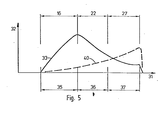
- the function of the extruder 1 can be followed by means of FIG. 5.
- the abscissa 31 indicates the axial position in the extruder 1 and the position of the pressure build-up zone 16, the intermediate zone 22 and the pressure consumption zone 27 is shown.
- the ordinate 32 gives. the pressure p.
- the solid pressure curve 33 shows the pressure curve in the extruder of FIG. 1, along the abscissa 31 the position of the solid area 35, the liquefaction area 36 and the liquid area 37 of a product treated in this way is indicated.
- the pressure of the solid material rises steeply. It reaches its maximum at the beginning of the intermediate zone 22, while the material is still solid or at least only liquefied to a small extent. Due to the progressive liquefaction, the coefficient of friction in the goods decreases and with it the pressure.
- the material is transferred to the pressure consumption zone 27, in which it is mixed and homogenized by the triangular extension 28 of the rotor 3.
- the pressure In front of the nozzle openings 12, the pressure reaches a minimum, for example 50 bar, which is still sufficient for extrusion.
- the cutting action of the extension 28 cuts the material in front of the nozzle openings 12 and escapes in portions to form product pieces 30, which are shown in FIG. 1 in the expanded state.
- the dashed curve 40 shows the pressure build-up in a conventional extruder, which as usual increases steadily up to the extrusion nozzle. Because the pressure is greatest here; fluctuations in the extrusion process propagate through the extrusion nozzle into the entire extruder.
- the position of the maximum pressure can vary depending on the compression behavior of the processed products and the degree of screw filling.
- This degree of screw filling can e.g. can be adjusted by regulating the supply. Products of very different nature can still be processed because the intermediate zone 22 controls most of the liquefaction area 36.
- an upstream steam feed apparatus can be assembled.
- this apparatus built like a continuous mixer for granular material, the material to be processed can be conditioned with steam.
- the squeezing nozzle 7 shown is particularly advantageous for the production of lumpy, expanded products.
- Other types of squeeze nozzles can of course be used for other products, e.g. those with one or more axial openings.
- the cylindrical rotor has 3 pocket grooves 45, 46, the direction of which alternates.
- the height of the wall 47 between a blind groove 45 opened on the side of the material inlet 5 and a blind groove 46 opened on the side of the squeezing nozzle 7 is slightly reduced in order to allow the transition of the material from the first to the second blind groove.
- the rotor 53 consists of a cylindrical part which is equipped with interrupted worm threads 55.
- the rotor 63 is of helical design with a large screw pitch, with 65 round attachments 66 being fastened to the rotor 63 between the worm threads.
- the rotor 73 consists of a cylindrical part which carries square attachments 75.
- the rotor 83 consists of disks 85, 86 which alternately have a larger and a smaller diameter.
- the housing and the rotor can be designed to expand conically, which would lead to an increase in the shear forces.
- the opening angle can be 0 to 90 °, preferably 60 °.
- the rotor 93 is cylindrical in the pressure consumption zone 27 and forms a narrow cylindrical gap 94 with the housing 92.
- the end 95 of the housing 92 and the end 96 of the rotor 93 form an annular ejection nozzle 97.
- a knife 98 fastened to the rotor 93 serves as a breaking or cutting device for the expanded product cylinder, which it comminutes into flakes.
- this extruder 91 flakes with very high starch digestion can be produced.
- the starting product was an undamped wholemeal corn flour that had been ground to grain sizes smaller than 5 mm.
- the bulk density was 0.5 kg per dm 3 .
- An expanded product was obtained with a bulk density of 0.1 kg per dm 3 and a starch digestion of 85%.
- Throughput uniformity was improved from an earlier coefficient of variation from 15% to 3%.
- the pulsation of the product flow was prevented thanks to the training with pressure build-up zone and pressure consumption zone.
- the throughput was 400 kg per hour.
- the starting product was a raw fiber-rich special piglet mix that had been ground to a grain size of less than 4 mm and contained 40% oats: 40% barley, 15% wheat bran and 5% various additives such as vitamins and minerals. As in Example 1, this product was undamped.
- the end product had a starch breakdown of over 75%.
- the throughput was 450 kg per hour.
- the starting product was a mink feed mix, with 45% fish meal, 10% potato pulp, and 20% various additives. Thanks to the effectiveness of the promotion in the pressure build-up zone, it was possible to add the remaining 25% of the mixture directly to the pressure consumption zone as fat addition. It is therefore possible to extrude such a product with a very high fat content.
- the throughput for this likewise undamped mixture was 340 kg per hour.
- the rotor 3 is thus divided into a pressure build-up zone 16, an intermediate zone 22 and a pressure consumption zone 27 from the material inlet 5 to the extrusion nozzle 7 of the extruder 1.
- the pressure consumption zone 27 serves for mixing and homogenizing the material before extrusion through the extrusion nozzle 7.
- Products from the group of expanded starch products or structured protein products are treated.
- the maximum pressure is reached in the not yet liquefied material or shortly after the liquefaction.
- the intermediate zone 22 absorbs differences in the position of the liquefaction area of different products.
Applications Claiming Priority (4)
| Application Number | Priority Date | Filing Date | Title |
|---|---|---|---|
| CH377280 | 1980-05-14 | ||
| CH3772/80 | 1980-05-14 | ||
| DE3023124 | 1980-06-20 | ||
| DE3023124A DE3023124C2 (de) | 1980-05-14 | 1980-06-20 | Extrudierverfahren und Extrudieranlage zur Durchführung des Verfahrens |
Publications (3)
| Publication Number | Publication Date |
|---|---|
| EP0039957A2 true EP0039957A2 (de) | 1981-11-18 |
| EP0039957A3 EP0039957A3 (en) | 1982-09-15 |
| EP0039957B1 EP0039957B1 (de) | 1985-10-02 |
Family
ID=25693804
Family Applications (1)
| Application Number | Title | Priority Date | Filing Date |
|---|---|---|---|
| EP81103715A Expired EP0039957B1 (de) | 1980-05-14 | 1981-05-14 | Extrudierverfahren |
Country Status (1)
| Country | Link |
|---|---|
| EP (1) | EP0039957B1 (ja) |
Cited By (8)
| Publication number | Priority date | Publication date | Assignee | Title |
|---|---|---|---|---|
| US4381184A (en) * | 1979-07-19 | 1983-04-26 | Samuel Hurni | Extruder apparatus |
| FR2578153A1 (fr) * | 1985-03-04 | 1986-09-05 | Clextral | Procede et dispositif de preparation d'un produit alimentaire a base de pate molle |
| EP0303460A1 (en) * | 1987-08-12 | 1989-02-15 | Unilever Plc | Starch product |
| FR2669194A1 (fr) * | 1990-11-16 | 1992-05-22 | Inotec International | Procede de traitement d'un produit, notamment de graines oleagineuses par extrusion et cuisson sous pression, et dispositif pour la mise en óoeuvre de ce procede. |
| EP0988948A1 (fr) * | 1998-09-16 | 2000-03-29 | Toulousaine de Recherche et de Developpement "T.R.D." Société Anonyme | Procédé de moulage d'un objet par injection à partir de matière première végétale |
| US10798950B2 (en) | 2013-08-08 | 2020-10-13 | General Mills, Inc. | System and method for producing an extruded protein product |
| CN112873982A (zh) * | 2020-12-28 | 2021-06-01 | 浙江财经大学 | 颗粒状中药材自动生产系统 |
| WO2021110750A1 (en) * | 2019-12-02 | 2021-06-10 | Sp Steel Aps | Apparatus for heat treatment of semi liquid or pasty food products |
Citations (7)
| Publication number | Priority date | Publication date | Assignee | Title |
|---|---|---|---|---|
| US3239882A (en) * | 1962-07-18 | 1966-03-15 | Sterling Extruder Corp | Dispersion head for extruder |
| DE1517038A1 (de) * | 1965-11-26 | 1969-06-12 | Gen Mills Inc | Verfahren und Vorrichtung zur Herstellung von Nahrungsmitteln |
| DE2532309A1 (de) * | 1974-08-02 | 1976-02-12 | Central Soya Co | Verfahren zur herstellung eines fleischersatz-produktes auf sojabasis |
| US4125635A (en) * | 1977-04-26 | 1978-11-14 | Ruyter Peter W A De | Method for making a meat analog |
| DE2744583A1 (de) * | 1977-10-04 | 1979-04-05 | Heinz Dipl Ing Weber | Doppelschneckenextruder |
| FR2432842A2 (fr) * | 1978-08-09 | 1980-03-07 | Sodes Sa | Produit alimentaire obtenu par cuisson-extrusion |
| GB2053788A (en) * | 1979-07-19 | 1981-02-11 | Buehler Ag Geb | Extruder for producing particles of expanded foodstuff material |
-
1981
- 1981-05-14 EP EP81103715A patent/EP0039957B1/de not_active Expired
Patent Citations (7)
| Publication number | Priority date | Publication date | Assignee | Title |
|---|---|---|---|---|
| US3239882A (en) * | 1962-07-18 | 1966-03-15 | Sterling Extruder Corp | Dispersion head for extruder |
| DE1517038A1 (de) * | 1965-11-26 | 1969-06-12 | Gen Mills Inc | Verfahren und Vorrichtung zur Herstellung von Nahrungsmitteln |
| DE2532309A1 (de) * | 1974-08-02 | 1976-02-12 | Central Soya Co | Verfahren zur herstellung eines fleischersatz-produktes auf sojabasis |
| US4125635A (en) * | 1977-04-26 | 1978-11-14 | Ruyter Peter W A De | Method for making a meat analog |
| DE2744583A1 (de) * | 1977-10-04 | 1979-04-05 | Heinz Dipl Ing Weber | Doppelschneckenextruder |
| FR2432842A2 (fr) * | 1978-08-09 | 1980-03-07 | Sodes Sa | Produit alimentaire obtenu par cuisson-extrusion |
| GB2053788A (en) * | 1979-07-19 | 1981-02-11 | Buehler Ag Geb | Extruder for producing particles of expanded foodstuff material |
Non-Patent Citations (1)
| Title |
|---|
| JAPAN PLASTICS AGE, Band 13, Nr. 5/6, Mai-Juni 1975, Seiten 29-46, * |
Cited By (11)
| Publication number | Priority date | Publication date | Assignee | Title |
|---|---|---|---|---|
| US4381184A (en) * | 1979-07-19 | 1983-04-26 | Samuel Hurni | Extruder apparatus |
| FR2578153A1 (fr) * | 1985-03-04 | 1986-09-05 | Clextral | Procede et dispositif de preparation d'un produit alimentaire a base de pate molle |
| EP0195702A1 (fr) * | 1985-03-04 | 1986-09-24 | Clextral | Procédé et dispositif de préparation d'un produit alimentaire à base de pâte molle |
| EP0303460A1 (en) * | 1987-08-12 | 1989-02-15 | Unilever Plc | Starch product |
| US5098727A (en) * | 1987-08-12 | 1992-03-24 | Van Den Bergh Foods Co., Division Of Conopco, Inc. | Process for preparing pregelatinized starch products |
| FR2669194A1 (fr) * | 1990-11-16 | 1992-05-22 | Inotec International | Procede de traitement d'un produit, notamment de graines oleagineuses par extrusion et cuisson sous pression, et dispositif pour la mise en óoeuvre de ce procede. |
| EP0988948A1 (fr) * | 1998-09-16 | 2000-03-29 | Toulousaine de Recherche et de Developpement "T.R.D." Société Anonyme | Procédé de moulage d'un objet par injection à partir de matière première végétale |
| FR2784046A1 (fr) * | 1998-09-16 | 2000-04-07 | Toulousaine De Rech Et De Dev | Procede de moulage d'un objet par injection a partir de matiere premiere vegetale |
| US10798950B2 (en) | 2013-08-08 | 2020-10-13 | General Mills, Inc. | System and method for producing an extruded protein product |
| WO2021110750A1 (en) * | 2019-12-02 | 2021-06-10 | Sp Steel Aps | Apparatus for heat treatment of semi liquid or pasty food products |
| CN112873982A (zh) * | 2020-12-28 | 2021-06-01 | 浙江财经大学 | 颗粒状中药材自动生产系统 |
Also Published As
| Publication number | Publication date |
|---|---|
| EP0039957B1 (de) | 1985-10-02 |
| EP0039957A3 (en) | 1982-09-15 |
Similar Documents
| Publication | Publication Date | Title |
|---|---|---|
| DE102004033344B4 (de) | Dosierzubringer und System zum Kneten und Strangpressen eines Materials | |
| DE2235784C3 (de) | Einschnecken-Extruder zum Mischen und Homogenisieren von hochviskosen Kautschukmischungen und hochviskosen Thermoplasten | |
| EP1324869B1 (de) | Mehrwellen-extruder und verfahren zur aufbereitung und/oder verarbeitung von mit füllstoff versetzten elastomeren | |
| EP1233855B1 (de) | Vorrichtung zum vorbehandeln und anschliessenden plastifizieren oder agglomerieren von kunststoffen | |
| EP0303728B1 (de) | Vorrichtung zum Extrudieren, Expandieren und/oder thermischen Behandeln von Stoffen und Stoffgemischen | |
| CH633990A5 (de) | Vorrichtung zum kontinuierlichen mischen von materialien. | |
| WO2019007756A1 (de) | Vorrichtung und verfahren zur extrusion von thermo-mechanisch verformbaren materialien in schüttgutform und schneckenextruder kompakter bauform | |
| EP0728066A1 (de) | Mehrwellige kontinuierlich arbeitende mischmaschine für plastifizierbare massen | |
| WO2013052986A1 (de) | Vorrichtung zum aufbereiten von kunststoffmaterial | |
| EP0617050A1 (de) | Verfahren und Einrichtung zum Herstellen eines Produktes, vorzugsweise eines geschäumten Produktes oder eines Schaumstoffmaterials aus nicht modifizierter Stärke | |
| DE2364507A1 (de) | Homogenisierungsextruder | |
| EP0039957B1 (de) | Extrudierverfahren | |
| DE2943820A1 (de) | Extruderanlage | |
| EP1434679A1 (de) | Ringextruder mit teilgekappten förderelementen im einzugsbereich | |
| DE3023124C2 (de) | Extrudierverfahren und Extrudieranlage zur Durchführung des Verfahrens | |
| EP0806280B1 (de) | Vorrichtung und Anlage zur Aufbereitung von Kunststoffgut | |
| DE1729145A1 (de) | Strangpresse fuer Kunststoffe | |
| DE2905717A1 (de) | Einschneckenextruder zum verarbeiten und strangpressen von thermoplastischen massen | |
| DE1271973B (de) | Kontinuierlich arbeitende Schneckenpresse fuer thermoplastische Kunststoffe von extrem geringem Schuettgewicht | |
| DE3342812A1 (de) | Vorrichtung und verfahren zur extrusion von zellulosehaltigen stoffen | |
| DE19608379C2 (de) | Schneckenpresse mit einer Vorrichtung zur Beeinflussung der Ausbeute | |
| WO1999017625A1 (de) | Vorrichtung zum bearbeiten von nahrungs- oder futtermitteln | |
| DE3815113A1 (de) | Verfahren und vorrichtung zur herstellung von caseinaten | |
| DE2312436A1 (de) | Kontinuierliche knetvorrichtung | |
| DE3205428A1 (de) | Stau- und mischelement fuer doppelschneckenextruder |
Legal Events
| Date | Code | Title | Description |
|---|---|---|---|
| PUAI | Public reference made under article 153(3) epc to a published international application that has entered the european phase |
Free format text: ORIGINAL CODE: 0009012 |
|
| AK | Designated contracting states |
Designated state(s): CH DE FR GB IT NL SE |
|
| PUAL | Search report despatched |
Free format text: ORIGINAL CODE: 0009013 |
|
| AK | Designated contracting states |
Designated state(s): CH DE FR GB IT NL SE |
|
| 17P | Request for examination filed |
Effective date: 19830314 |
|
| GRAA | (expected) grant |
Free format text: ORIGINAL CODE: 0009210 |
|
| AK | Designated contracting states |
Designated state(s): CH DE FR GB IT LI NL SE |
|
| PG25 | Lapsed in a contracting state [announced via postgrant information from national office to epo] |
Ref country code: NL Effective date: 19851002 Ref country code: IT Free format text: LAPSE BECAUSE OF FAILURE TO SUBMIT A TRANSLATION OF THE DESCRIPTION OR TO PAY THE FEE WITHIN THE PRESCRIBED TIME-LIMIT;WARNING: LAPSES OF ITALIAN PATENTS WITH EFFECTIVE DATE BEFORE 2007 MAY HAVE OCCURRED AT ANY TIME BEFORE 2007. THE CORRECT EFFECTIVE DATE MAY BE DIFFERENT FROM THE ONE RECORDED. Effective date: 19851002 Ref country code: FR Free format text: THE PATENT HAS BEEN ANNULLED BY A DECISION OF A NATIONAL AUTHORITY Effective date: 19851002 |
|
| PG25 | Lapsed in a contracting state [announced via postgrant information from national office to epo] |
Ref country code: SE Effective date: 19851030 |
|
| REF | Corresponds to: |
Ref document number: 3172487 Country of ref document: DE Date of ref document: 19851107 |
|
| EN | Fr: translation not filed | ||
| NLV1 | Nl: lapsed or annulled due to failure to fulfill the requirements of art. 29p and 29m of the patents act | ||
| PG25 | Lapsed in a contracting state [announced via postgrant information from national office to epo] |
Ref country code: LI Effective date: 19860531 Ref country code: CH Effective date: 19860531 |
|
| PLBE | No opposition filed within time limit |
Free format text: ORIGINAL CODE: 0009261 |
|
| STAA | Information on the status of an ep patent application or granted ep patent |
Free format text: STATUS: NO OPPOSITION FILED WITHIN TIME LIMIT |
|
| 26N | No opposition filed | ||
| GBPC | Gb: european patent ceased through non-payment of renewal fee | ||
| REG | Reference to a national code |
Ref country code: CH Ref legal event code: PL |
|
| PG25 | Lapsed in a contracting state [announced via postgrant information from national office to epo] |
Ref country code: DE Effective date: 19870203 |
|
| PG25 | Lapsed in a contracting state [announced via postgrant information from national office to epo] |
Ref country code: GB Effective date: 19881118 |