EP0039300A1 - Procédé et outillage pour la standardisation de la préparation des dents en vue de la pose des couronnes - Google Patents
Procédé et outillage pour la standardisation de la préparation des dents en vue de la pose des couronnes Download PDFInfo
- Publication number
- EP0039300A1 EP0039300A1 EP81420057A EP81420057A EP0039300A1 EP 0039300 A1 EP0039300 A1 EP 0039300A1 EP 81420057 A EP81420057 A EP 81420057A EP 81420057 A EP81420057 A EP 81420057A EP 0039300 A1 EP0039300 A1 EP 0039300A1
- Authority
- EP
- European Patent Office
- Prior art keywords
- cutter
- tooth
- abrasive
- flared
- volume
- Prior art date
- Legal status (The legal status is an assumption and is not a legal conclusion. Google has not performed a legal analysis and makes no representation as to the accuracy of the status listed.)
- Withdrawn
Links
- 238000002360 preparation method Methods 0.000 title claims 2
- 238000000034 method Methods 0.000 title description 14
- 238000003801 milling Methods 0.000 claims abstract description 39
- 238000003754 machining Methods 0.000 claims abstract description 29
- 239000011324 bead Substances 0.000 claims description 8
- 238000009434 installation Methods 0.000 claims description 4
- 210000000887 face Anatomy 0.000 description 14
- 230000001720 vestibular Effects 0.000 description 9
- 230000002093 peripheral effect Effects 0.000 description 5
- 241000220223 Fragaria Species 0.000 description 4
- 238000005909 Fraise reaction Methods 0.000 description 4
- 210000001847 jaw Anatomy 0.000 description 4
- 235000021012 strawberries Nutrition 0.000 description 4
- 210000003464 cuspid Anatomy 0.000 description 3
- 210000002455 dental arch Anatomy 0.000 description 3
- 210000000056 organ Anatomy 0.000 description 3
- 210000004763 bicuspid Anatomy 0.000 description 2
- 230000006698 induction Effects 0.000 description 2
- 238000003780 insertion Methods 0.000 description 2
- 230000037431 insertion Effects 0.000 description 2
- 230000001131 transforming effect Effects 0.000 description 2
- 206010049300 Gingival injury Diseases 0.000 description 1
- 244000178289 Verbascum thapsus Species 0.000 description 1
- 235000010599 Verbascum thapsus Nutrition 0.000 description 1
- 210000003323 beak Anatomy 0.000 description 1
- 230000009286 beneficial effect Effects 0.000 description 1
- 210000000988 bone and bone Anatomy 0.000 description 1
- 238000010438 heat treatment Methods 0.000 description 1
- 239000000463 material Substances 0.000 description 1
- 210000000214 mouth Anatomy 0.000 description 1
- 230000000149 penetrating effect Effects 0.000 description 1
- 238000003825 pressing Methods 0.000 description 1
- 239000000126 substance Substances 0.000 description 1
- 230000036346 tooth eruption Effects 0.000 description 1
- 230000009466 transformation Effects 0.000 description 1
Images

Classifications
-
- A—HUMAN NECESSITIES
- A61—MEDICAL OR VETERINARY SCIENCE; HYGIENE
- A61C—DENTISTRY; APPARATUS OR METHODS FOR ORAL OR DENTAL HYGIENE
- A61C3/00—Dental tools or instruments
- A61C3/02—Tooth drilling or cutting instruments; Instruments acting like a sandblast machine
-
- A—HUMAN NECESSITIES
- A61—MEDICAL OR VETERINARY SCIENCE; HYGIENE
- A61C—DENTISTRY; APPARATUS OR METHODS FOR ORAL OR DENTAL HYGIENE
- A61C17/00—Devices for cleaning, polishing, rinsing or drying teeth, teeth cavities or prostheses; Saliva removers; Dental appliances for receiving spittle
- A61C17/02—Rinsing or air-blowing devices, e.g. using fluid jets or comprising liquid medication
- A61C17/0205—Container filling apparatus
Definitions
- the present invention relates to a method and a tool for cutting teeth for the installation of crowns.
- each of these faces is associated with a plane
- the four corresponding planes are parallel to the axis of the tooth.
- This axis itself corresponds substantially to the axis of insertion of the future prosthetic crown.
- the horizontal face corresponding to the base of the approximate spherical volume, which is the sealed face, is located at the junction of the tooth penetrating the gum and the bone supporting this tooth.
- the cusp volume and the cervical volume together form the coronary volume, an approximate spherical volume with a vertical median axis.
- the machining of the dental organ with a view to transforming it into an approximate straight trunk on which the metallic reconstruction of the dental organ must come to fit with gentle friction must be carried out freehand, using rotary tools.
- the volume to be transformed is inaccessible to machine tools such as routers or lathes.
- the tools used are cutters for which a cutter body is secured to a handle driven by an appropriate means.
- the machining processes known to date, which include the size of the tooth without preliminary roughing, do not allow absolute certainty of success of the work, on the one hand as regards the value of the taper, and on the other hand share regarding the location of the lower size limit.
- the invention aims to overcome these drawbacks with a method and a tool for obtaining a much more precise result, and less random.
- the tooth machining sequences must follow a defined procedure by the morphology of the coronary volume.
- the choice of instrumentation is induced by the dimension of this coronal volume in the vertical direction.
- operations a) to e) apply to the four lingual, vestibular, distal and mesial flanks of the tooth.
- a cutter used for the execution of operation a) is characterized in that it comprises a cutter body with lateral active surface mounted on the end of a handle and integral, in the extension of the handle, with a straight stop with rounded end, the length of which is at most equal to half the distance separating the apices of the spherical volume approximated to the tooth considered.
- a cutter used for the execution of operation b) and operation c) is characterized in that it has substantially the shape of a diabolo, with an active lateral surface and at least one edge at each end of this surface.
- a milling cutter used for the execution of operation d) is characterized in that it comprises a frustoconical active lateral surface with low taper, its end of large section being integral with the end of a handle, and its end of small section constituting a smooth stop.
- a milling cutter used for the execution of operation e) is characterized in that it comprises, from the end of a handle: a smooth cylindrical abutment surface intended to bear on the lateral frustoconical surface of the tooth; an annular abutment surface intended to bear on the shoulder sidewalk of the tooth; in the center of this flat annular surface, a curved, concave, convex, or rectilinear generator active part.
- the aim of the process according to the invention is to carry out cutting work on the tooth which consists in transforming an approximate spherical volume into a straight truncated cone allowing the seat of a prosthetic crown subsequently ensuring the reconstruction of a complete tooth.
- the method according to the invention comprises the following successive operations:
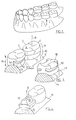
- This operation consists in cutting on the vestibular face 2 and on the lingual face 3 of the tooth a linear groove 12 situated at a constant distance from the sealed base 13 of the approximate spherical volume of the tooth, this distance 14 being at most equal to the half the height 15 separating the upper and lower ends of the approximate spherical volume.
- a cutter 16 is used for this, which is guided automatically by pressing on the edge of the gum, at the base of the cervical volume of the tooth (FIG. 23).
- the cusp volume delimited above the groove 12 is methodically machined using a roughing cutter 17 (fiô 24).
- This machining 18 is continued over the entire periphery of the tooth, that is to say also at the level of the distal 4 and nasal 5 faces, even if the latter could not be provided with a guide groove due to the closeness of the adjacent teeth (fig 4 and 25).
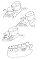
- the same roughing cutter 17 (fig 26) is used to machine the cervical volume defined below the groove 12, and to extend this machining 19 to the entire periphery of the tooth. While performing the roughing of the size of the flanks of the tooth, a peripheral shoulder pavement 20 is machined. The precision of this machining is obtained by the use of a cutter 17 of appropriate height, thanks to the presence of the groove 12 located at a constant distance from the cervical base of the tooth.
- a chamfer 24 is cut (fig 28 ).
- the milling cutter 23, with "cane tip”, makes it possible to obtain a regular chamfer, of constant height and width over the entire periphery of the tooth.
- the edge of the dencive 11 is pushed outwards, or slightly curetted.
- Such rotary curettage is known to be beneficial.
- the gum will then return to its normal place around the thinned lower edge of the prosthetic crown 25.
- Figure 8 provides an aspect of the jaw in which the cut tooth 1 is ready to receive the crown.
- the cutter 16 used for the execution of operation a) and represented in FIG. 9 comprises a cutter body 26 with an active lateral surface disposed between two smooth cylindrical surfaces of support 27 and 28 coaxial with a handle 29.
- the surfaces 27 and 28 can be of the same diameter.
- the bearing surface 27 extends between the axial end of the handle 29 and the cutter body 26, while the free end of the surface 28 can be rounded.
- the distance 30 between this free end and the middle of the cutter body 26 is at most equal to half the total height of the spherical volume approached by the tooth to be machined.
- the cutter body 26 can be designed in different ways.
- the drawing shows a body comprising two parts symmetrical to each other with respect to the plane passing through the middle of the body of the milling cutter, the two parts with concave generatrix being separated from each other by an edge, but this provision is not limiting, since we could just as easily design a cutter whose body has no symmetry, no edge, and generators concave, convex, broken line, and others.
- this cutter To use this cutter, place its rounded end with slight support on the edge of the gum line, along the line where the sidewalk 20 will then be cut, this line thus usually being the gum-tooth junction line, and the milling body mills groove 12 halfway up (fig 23). Therefore, the groove 12 remains at all points away from the line defined by the gum 11 along the tooth 1. In the case where the machining of the groove 12 is made impossible over the entire periphery of the tooth to be cut due to the presence of neighboring teeth, the size is made so that the vestibular and lingual portions of the throat 12 stop mesially and distally in line with the narrowing of the tooth at the gingival level.
- the milling cutter 17 used for the execution of operations b) and c), and represented in FIG. 10, has a milling cutter body which assumes the shape of a diabolo, with a groove 31 with a concave generator situated between two edges of end 32 and 33.
- the edge 32 located on the side of the handle 34 of the tool is adjacent to an annular surface 35 which, like the groove 31, can be abrasive.
- the end face 36 located beyond the edge 33 may be a smooth face.
- the machining is carried out by maintaining the axis of the cutter substantially parallel to the axis of the future prosthetic current, or in slight convergence with this axis, the active generator of the groove 31 in front remain "parallel" to the cord supporting the approximate spherical volume of the tooth in the cusp portion.
- the depth of the machining 18 carried out is equal to the diameter of the cutter body at the edges, or the groove.
- This milling cutter can also be used for machining the occlusal face 6 of the tooth.
- it is the medial groove with mesio-distal orientation 38 of the occlusal face of the tooth 1 which is used as induction and guide groove (fig 26).
- the handle of the cutter is then oriented parallel to the considered half of the occlusal face 6.
- the handle of the cutter is oriented lingually, while the body of the cutter is oriented vestibularly, while for machining the vestibular half 6b of the occlusal face, the handle of the cutter is oriented vestibularly and the body of the cutter lingually.
- the bearing face 36 of the milling cutter 17 is engaged in the median groove 38 to machine horizontal grooves, by choosing either the diameter of the edges 32 and / or 33 (these edges not necessarily having the same diameter), or the diameter of the groove 31 as a machining depth guide.
- the machined grooves meet in a horizontal translational movement, according to the morphology of the slopes and cusp bulges of the face 6. In this way, terminal machining of the face 6 is thus obtained at the chosen depth.
- the preliminary machining of the cusp volume improves the vision towards the cervical volume, and allows better access to this cervical volune, something particularly appreciable vis-à-vis the gum-tooth junction line to which we must pay close attention. particular, on the one hand not to injure the gum unnecessarily, and on the other hand to obtain the best possible precision for the positioning of the junction line and finishing of the future prosthetic crown.
- the axis of the bur is placed in parallel with the axis of insertion of the future crown, the latter coinciding with the general axis 8 of the tooth (see fig 5 and 26).
- the edge 32 of the cutter body is engaged in the groove 12 machined in operation a).
- the machining performed is made to penetrate the depth aise.en f r by a horizontal movement of suitable amplitude.
- the milling cutter 21 used for the execution of operation d), and represented in FIG. 11, comprises a frustoconical active lateral surface 39 with a low taper whose end of larger section is integral with the end of a handle 40 and whose free end of smaller cross section constitutes a smooth transverse bearing surface 41.
- This concave or convex surface 41 must have the same shape as the face 36 of the cutter 17.
- the surface 41 is placed in abutment on the sidewalk 20 (fig 27) while maintaining the axis of the cutter in parallel with the general axis 8 of the tooth.
- a circular movement of the cutter 21 bearing on the sidewalk 20 allows the surfacing of a frustoconical surface by the abrasive side of the instrument.
- the taper of the frustoconical surface obtained is equal to that of the abrasive flank of the cutter 21.
- the milling cutter 23 used for the execution of operation e), and represented in FIG. 12, comprises, starting from the axial end of a handle 42: a smooth cylindrical abutment surface 43, a smooth flat annular surface abutment 44, and a muffled abrasive part 45, called "cane tip” or “cane beak", located in the center of the surface 44.
- the surface 44 may have a pointed or rounded end 45a (FIG. 12a), and a generator 45b convex, concave, straight, or in a broken line.
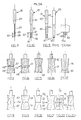
- Figures 13 and following show different cutters according to variants of the invention, which can be used to replace the cutters already described for the implementation of operations a) to c).
- the active surfaces of the milling cutter of FIG. 13 have a diabolo shape, with an annular bead 46 halfway up provided with an edge 47 in its plane of symmetry. This edge 47 is located inside the imaginary cylinder 48 constructed from the axial ends of the cutter body.
- FIG. 14 shows a substantially similar milling cutter in which the edge 47 is located outside the cylinder 48.
- the annular bead 46 comprises two surfaces whose generatrices can be, as the case may be: straight, convex or concaves.
- the cutter of Figure 15 comprises a dia- b olo shaped body with, at its free end, a concave conical face 49.
- the cutter of Figure 16 comprises a body shaped asymmetric diabolo, which comprises the c8té the handle, a tapered abrading surface 50 of relatively high taper peti- t e length, and the side of the free end of the milling cutter, a frustoconical abrasive surface 51 of low conicity of relatively large length.
- the body of the cutter of Figure 17 also includes a body in the form of an asymmetrical diabolo, but the orientations of the surfaces 50 and 51 are opposite to the previous ones.
- the cutter of Figure 18 has a diabolo-shaped body provided, conne the cutters of Figures 13 and 14, with an annular bead located substantially halfway up.
- the end surfaces 57 of the cutter body are concave and, since all the generatrices of this body are curves, there are no edges at the level of the bead 52.
- the milling cutter of FIG. 19 has a diabolo-shaped body which includes two abrasive surfaces with convexed generators and 54.
- the milling cutter of Figure 20 always has a body in form no diabolo, but with two abrasive surfaces 55 and 56 with concave generators.
- the milling cutter of FIG. 21 is similar to that of FIG. 18 in that it also comprises a diabolo-shaped body with an annular bead 52 devoid of an edge. However, while the generatrices of the end surfaces 57 of the cutter body of FIG. 18 are concave, the end surfaces 58 of the cutter body of FIG. 21 are convex.
- the milling cutter of FIG. 22 comprises a milling cutter body provided with four frustoconical abrasive surfaces with rectilinear generators forming together a double diabolo, with a central sharp edge 59.
- the milling cutter of FIG. 22a has a single edge, and a single flared surface 60, as well as a cylindrical portion 61.
Landscapes
- Health & Medical Sciences (AREA)
- Dentistry (AREA)
- Epidemiology (AREA)
- Life Sciences & Earth Sciences (AREA)
- Animal Behavior & Ethology (AREA)
- General Health & Medical Sciences (AREA)
- Public Health (AREA)
- Veterinary Medicine (AREA)
- Oral & Maxillofacial Surgery (AREA)
- Dental Tools And Instruments Or Auxiliary Dental Instruments (AREA)
Applications Claiming Priority (2)
| Application Number | Priority Date | Filing Date | Title |
|---|---|---|---|
| FR8009922 | 1980-04-25 | ||
| FR8009922A FR2481105A1 (fr) | 1980-04-25 | 1980-04-25 | Procede et outillage pour la standardisation de la preparation des dents en vue de la pose des couronnes |
Publications (1)
| Publication Number | Publication Date |
|---|---|
| EP0039300A1 true EP0039300A1 (fr) | 1981-11-04 |
Family
ID=9241586
Family Applications (1)
| Application Number | Title | Priority Date | Filing Date |
|---|---|---|---|
| EP81420057A Withdrawn EP0039300A1 (fr) | 1980-04-25 | 1981-04-16 | Procédé et outillage pour la standardisation de la préparation des dents en vue de la pose des couronnes |
Country Status (7)
| Country | Link |
|---|---|
| US (1) | US4473354A (enExample) |
| EP (1) | EP0039300A1 (enExample) |
| JP (1) | JPS5734843A (enExample) |
| CA (1) | CA1171308A (enExample) |
| ES (1) | ES267177Y (enExample) |
| FR (1) | FR2481105A1 (enExample) |
| IL (1) | IL62713A0 (enExample) |
Cited By (1)
| Publication number | Priority date | Publication date | Assignee | Title |
|---|---|---|---|---|
| WO1996014024A1 (de) * | 1994-11-04 | 1996-05-17 | Kaltenbach & Voigt Gmbh & Co. | System zur beseitigung eines defektes an einem zahn und einsatzteil oder werkzeug für ein solches system |
Families Citing this family (20)
| Publication number | Priority date | Publication date | Assignee | Title |
|---|---|---|---|---|
| JPS61106210U (enExample) * | 1984-12-19 | 1986-07-05 | ||
| US4992049A (en) * | 1988-05-12 | 1991-02-12 | Bernard Weissman | Method for applying a veneer facing to teeth |
| US5080588A (en) * | 1988-06-27 | 1992-01-14 | The University Of Michigan | Surface finishing apparatus and method |
| JP2730163B2 (ja) * | 1989-04-07 | 1998-03-25 | 日本合成ゴム株式会社 | 高トランス低ビニル共役ジエン系重合体の製造方法 |
| US5040978A (en) * | 1989-12-22 | 1991-08-20 | Dentsply Research & Development Corp. | Dental prophy angle |
| EP0806915A1 (en) * | 1995-02-03 | 1997-11-19 | 1162362 Ontario Inc. | Dental burr |
| FR2796264B1 (fr) | 1999-07-13 | 2001-10-12 | Dominique Logeart | Ensemble de fraises destine a la preparation d'une dent en vue de la pose d'une couronne prothetique |
| DE60028035D1 (de) | 1999-07-13 | 2006-06-22 | Dominique Logeart | Fräsanordnung für die vorbereitung eines zahnes zur kronenbefestigung |
| US7393211B2 (en) | 2001-10-15 | 2008-07-01 | Alfred Harper Ben Wilkinson | Tooth preparation instrument and system of its use |
| US7004757B2 (en) * | 2001-10-15 | 2006-02-28 | Alfred Harper Ben Wilkinson | Tooth preparation instrument and system of its use |
| US6511323B1 (en) * | 2001-10-15 | 2003-01-28 | Alfred Harper Ben Wilkinson | Tooth preparation instrument and system of its use |
| JP2005067006A (ja) | 2003-08-22 | 2005-03-17 | Fuji Photo Film Co Ltd | 平版印刷版の製版方法、平版印刷方法および平版印刷原版 |
| US20070238068A1 (en) * | 2006-04-06 | 2007-10-11 | Isaac Comfortes | Self-limiting depth gauge spherical dental burr and method of use |
| US8641419B2 (en) * | 2007-07-25 | 2014-02-04 | David J. Clark | Methods and devices for fixed dental restoration |
| US20100192375A1 (en) | 2009-02-02 | 2010-08-05 | Remedent Nv | Method for producing a dentist tool |
| US8640338B2 (en) | 2009-02-02 | 2014-02-04 | Viax Dental Technologies, LLC | Method of preparation for restoring tooth structure |
| ES2823723T3 (es) | 2011-05-26 | 2021-05-10 | Viax Dental Tech Llc | Herramienta dental y dispositivos de guiado |
| US11007035B2 (en) | 2017-03-16 | 2021-05-18 | Viax Dental Technologies Llc | System for preparing teeth for the placement of veneers |
| JP7210167B2 (ja) * | 2018-06-25 | 2023-01-23 | マニー株式会社 | 咬合面形成用バー |
| US12167951B1 (en) * | 2022-01-20 | 2024-12-17 | Gary Bram | Osteotomy drill bit to produce an optimally shaped jawbone opening for a dental implant and abutment |
Citations (4)
| Publication number | Priority date | Publication date | Assignee | Title |
|---|---|---|---|---|
| US2855673A (en) * | 1955-12-01 | 1958-10-14 | Gruenwald Siegfried | Dental instrument and method of preparing teeth |
| DE1516443A1 (de) * | 1965-03-20 | 1970-04-09 | Marc Reynaud | Vorrichtung zum Fraesen und zur Abdrucknahme fuer die Anfertigung kuenstlicher Stiftzaehne |
| DE2012268A1 (de) * | 1970-03-14 | 1971-10-07 | Schnitzer, Johann Georg, Dr , 7742 St Georgen | Schleifwerkzeugsatz für zahnarztliche Schleifgerate |
| BE845059A (nl) * | 1976-08-11 | 1976-12-01 | Werkwijze voor het afronden van de randen van een tandheelkundige prothese en frees voor het uitvoeren van die werkwijze |
Family Cites Families (5)
| Publication number | Priority date | Publication date | Assignee | Title |
|---|---|---|---|---|
| US2735181A (en) * | 1956-02-21 | Dental grinding tool | ||
| US749624A (en) * | 1904-01-12 | Dental bur | ||
| US2723455A (en) * | 1954-07-29 | 1955-11-15 | Oberley Ernest Paul | Dental tool |
| US4158256A (en) * | 1977-07-13 | 1979-06-19 | Lawrence Wiland | Detachable fastener for a dental cap and prosthodontic method utilizing the same |
| US4264307A (en) * | 1979-08-20 | 1981-04-28 | Neuwirth Siegmund A | Dental reducing tool |
-
1980
- 1980-04-25 FR FR8009922A patent/FR2481105A1/fr active Granted
-
1981
- 1981-04-16 EP EP81420057A patent/EP0039300A1/fr not_active Withdrawn
- 1981-04-24 ES ES1981267177U patent/ES267177Y/es not_active Expired
- 1981-04-24 US US06/256,882 patent/US4473354A/en not_active Expired - Fee Related
- 1981-04-24 IL IL62713A patent/IL62713A0/xx unknown
- 1981-04-24 JP JP6320981A patent/JPS5734843A/ja active Pending
- 1981-04-24 CA CA000376164A patent/CA1171308A/fr not_active Expired
Patent Citations (4)
| Publication number | Priority date | Publication date | Assignee | Title |
|---|---|---|---|---|
| US2855673A (en) * | 1955-12-01 | 1958-10-14 | Gruenwald Siegfried | Dental instrument and method of preparing teeth |
| DE1516443A1 (de) * | 1965-03-20 | 1970-04-09 | Marc Reynaud | Vorrichtung zum Fraesen und zur Abdrucknahme fuer die Anfertigung kuenstlicher Stiftzaehne |
| DE2012268A1 (de) * | 1970-03-14 | 1971-10-07 | Schnitzer, Johann Georg, Dr , 7742 St Georgen | Schleifwerkzeugsatz für zahnarztliche Schleifgerate |
| BE845059A (nl) * | 1976-08-11 | 1976-12-01 | Werkwijze voor het afronden van de randen van een tandheelkundige prothese en frees voor het uitvoeren van die werkwijze |
Cited By (1)
| Publication number | Priority date | Publication date | Assignee | Title |
|---|---|---|---|---|
| WO1996014024A1 (de) * | 1994-11-04 | 1996-05-17 | Kaltenbach & Voigt Gmbh & Co. | System zur beseitigung eines defektes an einem zahn und einsatzteil oder werkzeug für ein solches system |
Also Published As
| Publication number | Publication date |
|---|---|
| ES267177Y (es) | 1983-10-16 |
| FR2481105B1 (enExample) | 1983-09-02 |
| CA1171308A (fr) | 1984-07-24 |
| US4473354A (en) | 1984-09-25 |
| JPS5734843A (en) | 1982-02-25 |
| FR2481105A1 (fr) | 1981-10-30 |
| IL62713A0 (en) | 1981-06-29 |
| ES267177U (es) | 1983-03-16 |
Similar Documents
| Publication | Publication Date | Title |
|---|---|---|
| EP0039300A1 (fr) | Procédé et outillage pour la standardisation de la préparation des dents en vue de la pose des couronnes | |
| EP0214962B1 (fr) | Implant dentaire pour la fixation de protheses dentaires fixes | |
| EP1478301B9 (fr) | Outil de preparation osseuse utilisable notamment en medecine dentaire et dispositif pour sa mise en oeuvre | |
| EP1753365B1 (fr) | Guide chirurgical implantaire sur mesure et fraise associée et leur procédé de fabrication | |
| CH691163A5 (fr) | Instrument de chirurgie dentaire pour l'élargissement mécanique rapide de l'entrée du canal et la rectification spécifique des premiers deux tiers. | |
| EP1318763A2 (fr) | Jeu d'implants et implants correspondants | |
| FR2898485A1 (fr) | Dispositif de guidage d'un foret implantaire | |
| EP0151086A2 (fr) | Dispositif de préparation et de positionnement de "Dies" ou modeles positifs unitaires pour tout ou partie de l'une ou des deux arcades dentaires et de mise en occluseur ou articulateur | |
| CA2379073C (fr) | Ensemble de fraises destine a la preparation d'une dent en vue de la pose d'une couronne prothetique | |
| EP0780100B1 (fr) | Instrument pour l'alésage des canaux radiculaires dentaires | |
| FR2571608A1 (fr) | Tenon dentaire pour le maintien d'une suprastructure prothetique | |
| FR2635455A1 (fr) | Ensemble prothetique pour implant dentaire | |
| EP1830737A1 (fr) | Dispositif destine a etre utilise lors de la reconstitution dentaire | |
| WO2012123654A1 (fr) | Implant dentaire | |
| EP1251792B1 (fr) | Clef de descellement | |
| FR2737847A1 (fr) | Implant-taraud comprimant | |
| KR102252139B1 (ko) | 임플란트의 픽스쳐에 체결된 어버트먼트 취출장치 | |
| EP0159308B1 (fr) | Outil rotatif et méthode pour la confection de protheses totales en resine synthetique | |
| FR2516784A1 (fr) | Nouvel implant, outil pour la mise en place de celui-ci et procede de realisations implantaires | |
| CH700426B1 (fr) | Tournevis à usage dentaire ou chirurgical ainsi que procédé pour la fabrication d'un tel tournevis. | |
| FR3017531B1 (fr) | Implant dento-osteo integre | |
| WO2002069834A1 (fr) | Procede de fabrication et attachement pour protheses dentaires mobiles definitives ou provisoires | |
| CH677600A5 (enExample) | ||
| FR2716795A1 (fr) | Fraises dentaires. | |
| WO2012175724A2 (fr) | Instrument endodontique presentant au moins une arete de decoupe frontale |
Legal Events
| Date | Code | Title | Description |
|---|---|---|---|
| PUAI | Public reference made under article 153(3) epc to a published international application that has entered the european phase |
Free format text: ORIGINAL CODE: 0009012 |
|
| AK | Designated contracting states |
Designated state(s): AT BE CH DE GB IT SE |
|
| 17P | Request for examination filed |
Effective date: 19811027 |
|
| STAA | Information on the status of an ep patent application or granted ep patent |
Free format text: STATUS: THE APPLICATION IS DEEMED TO BE WITHDRAWN |
|
| 18D | Application deemed to be withdrawn |
Effective date: 19870328 |