EP0039255B1 - Capteur de pression pour organe rotatif - Google Patents
Capteur de pression pour organe rotatif Download PDFInfo
- Publication number
- EP0039255B1 EP0039255B1 EP81400244A EP81400244A EP0039255B1 EP 0039255 B1 EP0039255 B1 EP 0039255B1 EP 81400244 A EP81400244 A EP 81400244A EP 81400244 A EP81400244 A EP 81400244A EP 0039255 B1 EP0039255 B1 EP 0039255B1
- Authority
- EP
- European Patent Office
- Prior art keywords
- shaft
- assembly
- housing
- pressure
- detector according
- Prior art date
- Legal status (The legal status is an assumption and is not a legal conclusion. Google has not performed a legal analysis and makes no representation as to the accuracy of the status listed.)
- Expired
Links
Images

Classifications
-
- B—PERFORMING OPERATIONS; TRANSPORTING
- B60—VEHICLES IN GENERAL
- B60C—VEHICLE TYRES; TYRE INFLATION; TYRE CHANGING; CONNECTING VALVES TO INFLATABLE ELASTIC BODIES IN GENERAL; DEVICES OR ARRANGEMENTS RELATED TO TYRES
- B60C23/00—Devices for measuring, signalling, controlling, or distributing tyre pressure or temperature, specially adapted for mounting on vehicles; Arrangement of tyre inflating devices on vehicles, e.g. of pumps or of tanks; Tyre cooling arrangements
- B60C23/02—Signalling devices actuated by tyre pressure
- B60C23/04—Signalling devices actuated by tyre pressure mounted on the wheel or tyre
- B60C23/0408—Signalling devices actuated by tyre pressure mounted on the wheel or tyre transmitting the signals by non-mechanical means from the wheel or tyre to a vehicle body mounted receiver
- B60C23/0422—Signalling devices actuated by tyre pressure mounted on the wheel or tyre transmitting the signals by non-mechanical means from the wheel or tyre to a vehicle body mounted receiver characterised by the type of signal transmission means
- B60C23/0427—Near field transmission with inductive or capacitive coupling means
- B60C23/043—Near field transmission with inductive or capacitive coupling means using transformer type signal transducers, e.g. rotary transformers
Definitions
- the present invention relates to a pressure sensor for a rotary member, making it possible to supply an electric voltage which is a function of the pressure which prevails in the member.
- the invention finds a particularly important, although not exclusive, application in the measurement of the pressure prevailing in the tires of aircraft wheels.
- the invention aims to provide a space-saving sensor, the presence of which does not exclude that of other devices which must also be driven by the rotary member, and which can easily be carried out in a sealed manner.
- the invention proposes in particular a pressure sensor comprising a fixed housing in which a central shaft for coupling with said member is mounted fixed in translation and free in rotation, characterized in particular in that it comprises a movable assembly sliding on the shaft, connected to the shaft by deformable walls which delimit, with surfaces of the crew, a pressure chamber connected to the interior of said member by a passage formed in the shaft, said surfaces of the crew being such that the pressure exerts on the crew a resultant axial force which is opposed to that of a return spring placed between the shaft and the crew, and in that said crew comprises a ferromagnetic mass ensuring variable coupling between the exciting and receiving coils of a differential transformer carried by the housing.
- the ferromagnetic mass has a shape such that its axial displacement varies the reluctance of the differential transformer and induces a signal on the take-up coil, advantageously placed between two excitation coils in the axial direction.
- the shaft is provided with radial flanges of different diameter, connected, by bellows constituting the deformable walls, to opposite faces of a disc secured to the movable assembly, so as to delimit surfaces different action of pressure on both sides of the disc.
- the box will be fixed on the fixed spindle, while the shaft will ensure the coupling between the rotary part of the wheel and the tachometer generator which is generally necessary, in particular to control the traction control system.
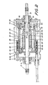
- Figs. 1 and 2 which accompany it and which show, by way of examples, two embodiments of the sensor, in section along a plane passing through its axis.
- the senor 10 comprises a housing 11 made of non-magnetic material, for example of light alloy, provided with means (not shown) making it possible to fix it on a rocket.
- This housing 11 carries sealed bearings 13 supporting a rotary shaft 12 and retaining it in translation.
- the shaft is made up of two sections 14 and 15 fixed to each other by a threaded connection.
- One of the sections is provided with a thread and a nut 16 for coupling with the rotating part of a wheel.
- the other section 15 is provided with a grooved extension 17 for connection with another member, such as a tachometer generator.
- the two sections protrude through terminal sealing partitions 18 of the housing 11.
- the shaft constitutes a movement transmission member at the same time as an input member for the sensor 10.
- an assembly 19 comprising a mass of ferromagnetic material 20, constituted in the embodiment represented by a ring of soft iron. Screws 21 and 22 fix this ring to cheeks 23 and 24 keyed sliding on the shaft 12. The screws 22 also retain, against an internal shoulder of the ring 20, a disc 25 pierced with a central hole of sufficient diameter so that a clearance remains between the disc 25 and the section 14 of the shaft 12.
- the deformable partitions constituted by bellows 26 and 27, sealingly connect the disc 25 to flanges 28 and 29 respectively formed on the sections 14 and 15.
- These bellows 26 and 27 delimit, with the flanges 28 and 29 and the disc 25, a pressure chamber 30 into which opens a pressure supply passage 31 pierced in the section 14.
- the bellows 26 and 27 have different radial dimensions, so that the pressure prevailing in the chamber 30 exerts on the disc 25 a resulting force, directed from left to right in the figure.
- Resilient calibrated return means are provided to balance this force.
- they are constituted by a return spring 32 compressed between the disc 25 and a washer 33 whose position is adjustable using a setting nut 34.
- a stop 35 makes it possible to limit the movement of the mobile assembly 19 when no pressure reigns in the chamber 30.
- the means of the sensor 10 intended to supply an electrical signal in response to the axial displacements of the crew 19 are constituted by a differential transformer with variable reluctance.
- This transformer comprises a take-up coil 36 carried by the housing 11 between two excitation coils 37.
- the magnetic circuit of this differential transformer comprises a ring 38 placed in the housing 11 and providing a recess for receiving the coils 36 and 37, as well as the ground ferromagnetic 20 of the movable member 19. In this mass is formed a groove of axial dimension corresponding to that of the recess.
- the senor is easy to make and also to assemble, given the splitting of the shaft into two sections. It is easily adjustable at the factory by action on the calibration nut 34.
- the air gap of the magnetic circuit of the transformer can be reduced to a very low value, which gives the sensor a high sensitivity and makes it possible to achieve satisfactory precision, even by giving the moving element 19 a small amplitude of axial movement, of a few millimeters.
- the rotary shaft 12 is in one piece.
- the bellows 26 is placed around the bellows 27.
- the two bellows each connect a tip disc 40, secured to the cheek 23 by the screws 21, and a bulge 41 of the shaft, forming the flanges 28 and 29 between which the passage 31 opens into the chamber 30.
- the sensor is provided with means making it possible to adjust the pressure for which the electrical output signal is zero.
- These means comprise an adjustment nut 34 whose position is adjustable in the cheek 24 and which constitutes the support of the return spring 32.
- a screw 42 makes it possible to lock the nut 34 once the adjustment has been made.
- the variation in reluctance is obtained by providing the movable assembly with a ring 43 of material with high permeability, such as the alloy called Armco.
Landscapes
- Engineering & Computer Science (AREA)
- Mechanical Engineering (AREA)
- Measuring Fluid Pressure (AREA)
Applications Claiming Priority (2)
| Application Number | Priority Date | Filing Date | Title |
|---|---|---|---|
| FR8004381 | 1980-02-27 | ||
| FR8004381A FR2476835A1 (fr) | 1980-02-27 | 1980-02-27 | Capteur de pression pour organe rotatif |
Publications (2)
| Publication Number | Publication Date |
|---|---|
| EP0039255A1 EP0039255A1 (fr) | 1981-11-04 |
| EP0039255B1 true EP0039255B1 (fr) | 1984-04-18 |
Family
ID=9239067
Family Applications (1)
| Application Number | Title | Priority Date | Filing Date |
|---|---|---|---|
| EP81400244A Expired EP0039255B1 (fr) | 1980-02-27 | 1981-02-17 | Capteur de pression pour organe rotatif |
Country Status (4)
| Country | Link |
|---|---|
| US (1) | US4373385A (enExample) |
| EP (1) | EP0039255B1 (enExample) |
| DE (1) | DE3163148D1 (enExample) |
| FR (1) | FR2476835A1 (enExample) |
Families Citing this family (2)
| Publication number | Priority date | Publication date | Assignee | Title |
|---|---|---|---|---|
| US5704073A (en) | 1995-08-01 | 1998-01-06 | Figgie International Inc. | Quick donning goggles for use with breathing mask |
| US6279403B1 (en) | 1999-10-22 | 2001-08-28 | Henlex, Inc. | Differential pressure triggering device |
Citations (1)
| Publication number | Priority date | Publication date | Assignee | Title |
|---|---|---|---|---|
| US3374460A (en) * | 1964-04-06 | 1968-03-19 | Cie Generale Des Establissment | System for signaling conditions on relatively moving members of a vehicle |
Family Cites Families (5)
| Publication number | Priority date | Publication date | Assignee | Title |
|---|---|---|---|---|
| GB330898A (en) * | 1929-03-18 | 1930-06-18 | Arthur George Foulds | Improvements relating to deflation indicating means for motor vehicles and aircraft fitted with pneumatic tyres |
| US2056064A (en) * | 1932-10-15 | 1936-09-29 | Fenton Warren | Alarm and inflation equalizer for pneumatic tires |
| US2822530A (en) * | 1956-02-17 | 1958-02-04 | Geter J Roten | Tire pressure indicating system |
| US3730146A (en) * | 1971-11-29 | 1973-05-01 | Gen Motors Corp | Pressure-inductance transducer |
| US4161886A (en) * | 1978-04-19 | 1979-07-24 | Chrysler Corporation | Pressure transducer and method |
-
1980
- 1980-02-27 FR FR8004381A patent/FR2476835A1/fr active Granted
-
1981
- 1981-02-17 EP EP81400244A patent/EP0039255B1/fr not_active Expired
- 1981-02-17 DE DE8181400244T patent/DE3163148D1/de not_active Expired
- 1981-02-20 US US06/236,555 patent/US4373385A/en not_active Expired - Fee Related
Patent Citations (1)
| Publication number | Priority date | Publication date | Assignee | Title |
|---|---|---|---|---|
| US3374460A (en) * | 1964-04-06 | 1968-03-19 | Cie Generale Des Establissment | System for signaling conditions on relatively moving members of a vehicle |
Also Published As
| Publication number | Publication date |
|---|---|
| FR2476835A1 (fr) | 1981-08-28 |
| FR2476835B1 (enExample) | 1982-04-16 |
| DE3163148D1 (en) | 1984-05-24 |
| US4373385A (en) | 1983-02-15 |
| EP0039255A1 (fr) | 1981-11-04 |
Similar Documents
| Publication | Publication Date | Title |
|---|---|---|
| EP0576310B1 (fr) | Dispositif de mesure d'un couple de torsion sur un arbre tournant | |
| EP1053457B1 (fr) | Capteur de couple pour arbre tournant | |
| EP1239274B1 (fr) | Dispositif de mesure analogique d'un couple de torsion, colonne de direction et module le comprenant | |
| EP0326454B1 (fr) | Montage de palier à roulement avec dispositif capteur | |
| EP0847520B1 (fr) | Dispositif de mesure de couple de torsion d'un arbre tournant | |
| FR2862382A1 (fr) | Systeme capteur de couple absolu de torsion et module le comprenant | |
| FR2816047A1 (fr) | Dispositif de palier a roulement instrumente, notamment pour volant de commande | |
| FR2462696A1 (fr) | Dispositif de surveillance de la pression des pneumatiques d'un aerodyne | |
| EP0474562B1 (fr) | Manchon de roulement à codeur pour dispositif capteur | |
| EP0039255B1 (fr) | Capteur de pression pour organe rotatif | |
| FR2459462A1 (fr) | Dynanometre a diaphragmes | |
| EP4271976B1 (fr) | Ensemble de transmission et de mesure de couple pour une turbomachine | |
| EP0923716B1 (fr) | Perfectionnement a un dispositif de mesure de couple de torsion d'un arbre tournant | |
| FR2911528A1 (fr) | Outil de vissage incluant un ou plusieurs capteurs de couple montes pour mesurer des deformations dans un plan perpendiculaire a un axe de revolution, et support de capteur correspondant | |
| FR3124239A1 (fr) | Dispositif d’actionnement électromagnétique et système de transmission équipé de ce dispositif d’actionnement électromagnétique | |
| EP1029226B1 (fr) | Dispositif de mesure d'un couple de torsion sur un element mecanique | |
| FR2563795A1 (fr) | Capteur de couple pour direction assistee | |
| FR3163133A1 (fr) | Dispositif de freinage d’aéronef équipé d’un capteur de mesure du couple de freinage dudit dispositif. | |
| EP0517592A1 (fr) | Procédé et dispositif d'étalonnage de couplemètre et couplemètre compact adapté au dispositif | |
| FR2537278A1 (fr) | Manometre transmetteur | |
| EP0189721A1 (fr) | Procédé et dispositif de mesure de l'angle de braquage d'une roue avant de véhicule automobile | |
| FR2879990A1 (fr) | Systeme d'actionnement d'arbre de direction instrumente comprenant un centre fixe | |
| EP0294279B1 (fr) | Enceinte étanche comportant une sortie d'arbre | |
| FR2940436A1 (fr) | Dispositif d'etalonnage d'appareils de mesure de contraintes | |
| FR2930821A3 (fr) | Dispositif de mesure d'un couple de torsion et de vitesse pour roue de vehicule automobile |
Legal Events
| Date | Code | Title | Description |
|---|---|---|---|
| PUAI | Public reference made under article 153(3) epc to a published international application that has entered the european phase |
Free format text: ORIGINAL CODE: 0009012 |
|
| AK | Designated contracting states |
Designated state(s): DE GB NL SE |
|
| 17P | Request for examination filed |
Effective date: 19810914 |
|
| GRAA | (expected) grant |
Free format text: ORIGINAL CODE: 0009210 |
|
| AK | Designated contracting states |
Designated state(s): DE GB NL SE |
|
| PG25 | Lapsed in a contracting state [announced via postgrant information from national office to epo] |
Ref country code: SE Effective date: 19840418 Ref country code: NL Effective date: 19840418 |
|
| REF | Corresponds to: |
Ref document number: 3163148 Country of ref document: DE Date of ref document: 19840524 |
|
| NLV1 | Nl: lapsed or annulled due to failure to fulfill the requirements of art. 29p and 29m of the patents act | ||
| PLBE | No opposition filed within time limit |
Free format text: ORIGINAL CODE: 0009261 |
|
| STAA | Information on the status of an ep patent application or granted ep patent |
Free format text: STATUS: NO OPPOSITION FILED WITHIN TIME LIMIT |
|
| 26N | No opposition filed | ||
| PGFP | Annual fee paid to national office [announced via postgrant information from national office to epo] |
Ref country code: GB Payment date: 19940211 Year of fee payment: 14 |
|
| PGFP | Annual fee paid to national office [announced via postgrant information from national office to epo] |
Ref country code: DE Payment date: 19940218 Year of fee payment: 14 |
|
| PG25 | Lapsed in a contracting state [announced via postgrant information from national office to epo] |
Ref country code: GB Effective date: 19950217 |
|
| GBPC | Gb: european patent ceased through non-payment of renewal fee |
Effective date: 19950217 |
|
| PG25 | Lapsed in a contracting state [announced via postgrant information from national office to epo] |
Ref country code: DE Effective date: 19951101 |