EP0039255B1 - Pressure transducer for a rotating implement - Google Patents
Pressure transducer for a rotating implement Download PDFInfo
- Publication number
- EP0039255B1 EP0039255B1 EP81400244A EP81400244A EP0039255B1 EP 0039255 B1 EP0039255 B1 EP 0039255B1 EP 81400244 A EP81400244 A EP 81400244A EP 81400244 A EP81400244 A EP 81400244A EP 0039255 B1 EP0039255 B1 EP 0039255B1
- Authority
- EP
- European Patent Office
- Prior art keywords
- shaft
- assembly
- housing
- pressure
- detector according
- Prior art date
- Legal status (The legal status is an assumption and is not a legal conclusion. Google has not performed a legal analysis and makes no representation as to the accuracy of the status listed.)
- Expired
Links
Images

Classifications
-
- B—PERFORMING OPERATIONS; TRANSPORTING
- B60—VEHICLES IN GENERAL
- B60C—VEHICLE TYRES; TYRE INFLATION; TYRE CHANGING; CONNECTING VALVES TO INFLATABLE ELASTIC BODIES IN GENERAL; DEVICES OR ARRANGEMENTS RELATED TO TYRES
- B60C23/00—Devices for measuring, signalling, controlling, or distributing tyre pressure or temperature, specially adapted for mounting on vehicles; Arrangement of tyre inflating devices on vehicles, e.g. of pumps or of tanks; Tyre cooling arrangements
- B60C23/02—Signalling devices actuated by tyre pressure
- B60C23/04—Signalling devices actuated by tyre pressure mounted on the wheel or tyre
- B60C23/0408—Signalling devices actuated by tyre pressure mounted on the wheel or tyre transmitting the signals by non-mechanical means from the wheel or tyre to a vehicle body mounted receiver
- B60C23/0422—Signalling devices actuated by tyre pressure mounted on the wheel or tyre transmitting the signals by non-mechanical means from the wheel or tyre to a vehicle body mounted receiver characterised by the type of signal transmission means
- B60C23/0427—Near field transmission with inductive or capacitive coupling means
- B60C23/043—Near field transmission with inductive or capacitive coupling means using transformer type signal transducers, e.g. rotary transformers
Definitions
- the present invention relates to a pressure sensor for a rotary member, making it possible to supply an electric voltage which is a function of the pressure which prevails in the member.
- the invention finds a particularly important, although not exclusive, application in the measurement of the pressure prevailing in the tires of aircraft wheels.
- the invention aims to provide a space-saving sensor, the presence of which does not exclude that of other devices which must also be driven by the rotary member, and which can easily be carried out in a sealed manner.
- the invention proposes in particular a pressure sensor comprising a fixed housing in which a central shaft for coupling with said member is mounted fixed in translation and free in rotation, characterized in particular in that it comprises a movable assembly sliding on the shaft, connected to the shaft by deformable walls which delimit, with surfaces of the crew, a pressure chamber connected to the interior of said member by a passage formed in the shaft, said surfaces of the crew being such that the pressure exerts on the crew a resultant axial force which is opposed to that of a return spring placed between the shaft and the crew, and in that said crew comprises a ferromagnetic mass ensuring variable coupling between the exciting and receiving coils of a differential transformer carried by the housing.
- the ferromagnetic mass has a shape such that its axial displacement varies the reluctance of the differential transformer and induces a signal on the take-up coil, advantageously placed between two excitation coils in the axial direction.
- the shaft is provided with radial flanges of different diameter, connected, by bellows constituting the deformable walls, to opposite faces of a disc secured to the movable assembly, so as to delimit surfaces different action of pressure on both sides of the disc.
- the box will be fixed on the fixed spindle, while the shaft will ensure the coupling between the rotary part of the wheel and the tachometer generator which is generally necessary, in particular to control the traction control system.
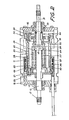
- Figs. 1 and 2 which accompany it and which show, by way of examples, two embodiments of the sensor, in section along a plane passing through its axis.
- the senor 10 comprises a housing 11 made of non-magnetic material, for example of light alloy, provided with means (not shown) making it possible to fix it on a rocket.
- This housing 11 carries sealed bearings 13 supporting a rotary shaft 12 and retaining it in translation.
- the shaft is made up of two sections 14 and 15 fixed to each other by a threaded connection.
- One of the sections is provided with a thread and a nut 16 for coupling with the rotating part of a wheel.
- the other section 15 is provided with a grooved extension 17 for connection with another member, such as a tachometer generator.
- the two sections protrude through terminal sealing partitions 18 of the housing 11.
- the shaft constitutes a movement transmission member at the same time as an input member for the sensor 10.
- an assembly 19 comprising a mass of ferromagnetic material 20, constituted in the embodiment represented by a ring of soft iron. Screws 21 and 22 fix this ring to cheeks 23 and 24 keyed sliding on the shaft 12. The screws 22 also retain, against an internal shoulder of the ring 20, a disc 25 pierced with a central hole of sufficient diameter so that a clearance remains between the disc 25 and the section 14 of the shaft 12.
- the deformable partitions constituted by bellows 26 and 27, sealingly connect the disc 25 to flanges 28 and 29 respectively formed on the sections 14 and 15.
- These bellows 26 and 27 delimit, with the flanges 28 and 29 and the disc 25, a pressure chamber 30 into which opens a pressure supply passage 31 pierced in the section 14.
- the bellows 26 and 27 have different radial dimensions, so that the pressure prevailing in the chamber 30 exerts on the disc 25 a resulting force, directed from left to right in the figure.
- Resilient calibrated return means are provided to balance this force.
- they are constituted by a return spring 32 compressed between the disc 25 and a washer 33 whose position is adjustable using a setting nut 34.
- a stop 35 makes it possible to limit the movement of the mobile assembly 19 when no pressure reigns in the chamber 30.
- the means of the sensor 10 intended to supply an electrical signal in response to the axial displacements of the crew 19 are constituted by a differential transformer with variable reluctance.
- This transformer comprises a take-up coil 36 carried by the housing 11 between two excitation coils 37.
- the magnetic circuit of this differential transformer comprises a ring 38 placed in the housing 11 and providing a recess for receiving the coils 36 and 37, as well as the ground ferromagnetic 20 of the movable member 19. In this mass is formed a groove of axial dimension corresponding to that of the recess.
- the senor is easy to make and also to assemble, given the splitting of the shaft into two sections. It is easily adjustable at the factory by action on the calibration nut 34.
- the air gap of the magnetic circuit of the transformer can be reduced to a very low value, which gives the sensor a high sensitivity and makes it possible to achieve satisfactory precision, even by giving the moving element 19 a small amplitude of axial movement, of a few millimeters.
- the rotary shaft 12 is in one piece.
- the bellows 26 is placed around the bellows 27.
- the two bellows each connect a tip disc 40, secured to the cheek 23 by the screws 21, and a bulge 41 of the shaft, forming the flanges 28 and 29 between which the passage 31 opens into the chamber 30.
- the sensor is provided with means making it possible to adjust the pressure for which the electrical output signal is zero.
- These means comprise an adjustment nut 34 whose position is adjustable in the cheek 24 and which constitutes the support of the return spring 32.
- a screw 42 makes it possible to lock the nut 34 once the adjustment has been made.
- the variation in reluctance is obtained by providing the movable assembly with a ring 43 of material with high permeability, such as the alloy called Armco.
Description
La présente invention a pour objet un capteur de pression pour organe rotatif, permettant de fournir une tension électrique fonction de la pression qui règne dans l'organe.The present invention relates to a pressure sensor for a rotary member, making it possible to supply an electric voltage which is a function of the pressure which prevails in the member.
L'invention trouve une application particulièrement importante, bien que non exclusive, dans la mesure de la pression régnant dans les pneumatiques de roues d'avions. On sait en effet que la présence d'un pneu éclaté ou dégonflé est source d'accident au décollage ou à l'atterrissage. Si l'inspection visuelle permet de déceler un pneu éclaté avant que l'avion ne quitte son poste de stationnement, la présence d'un ou de plusieurs pneumatiques dégonflés ou sous-gonflés peut au contraire passer inaperçue du personnel au sol. Il est en conséquence souhaitable de fournir une indication sur la pression qui règne dans les pneumatiques.The invention finds a particularly important, although not exclusive, application in the measurement of the pressure prevailing in the tires of aircraft wheels. We know that the presence of a flat or deflated tire is a source of accident on takeoff or landing. If the visual inspection reveals a burst tire before the airplane leaves its parking position, the presence of one or more deflated or under-inflated tires can on the contrary go unnoticed by the ground personnel. It is therefore desirable to provide an indication of the pressure prevailing in the tires.
Une solution possible au problème consiste à placer un capteur sur la partie tournante de la roue et à transmettre le signal électrique qu'il fournit par l'intermédiaire d'un collecteur électrique. Cette solution, qui implique un contact glissant, présente des inconvénients qui sont particulièrement graves lors du montage dans une roue d'avion, étant donné les écarts de température subis et la présence de polluant qui exige l'emploi d'un collecteur étanche.One possible solution to the problem consists in placing a sensor on the rotating part of the wheel and in transmitting the electrical signal which it provides via an electrical collector. This solution, which involves sliding contact, has drawbacks which are particularly serious during mounting in an airplane wheel, given the temperature differences experienced and the presence of pollutant which requires the use of a sealed collector.
L'invention vise à fournir un capteur de faible encombrement, dont la présence n'exclut pas celle d'autres dispositifs devant également être entraînés par l'organe rotatif, et facilement réalisable de façon étanche.The invention aims to provide a space-saving sensor, the presence of which does not exclude that of other devices which must also be driven by the rotary member, and which can easily be carried out in a sealed manner.
Dans ce but, l'invention propose notamment un capteur de pression comprenant un boîtier fixe dans lequel un arbre central de couplage avec ledit organe est monté fixe en translation et libre en rotation, caractérisé notamment en ce qu'il comporte un équipage mobile coulissant sur l'arbre, relié à l'arbre par des parois déformables qui délimitent, avec des surfaces de l'équipage, une chambre de pression reliée à l'intérieur dudit organe par un passage ménagé dans l'arbre, lesdites surfaces de l'équipage étant telles que la pression exerce sur l'équipage une force résultante axiale qui s'oppose à celle d'un ressort de rappel placé entre l'arbre et l'équipage, et en ce que ledit équipage comprend une masse ferromagnétique assurant un couplage variable entre les bobines excitatrices et réceptrices d'un transformateur différentiel porté par le boîtier. La masse ferromagnétique présente une forme telle que son déplacement axial fait varier la réluctance du transformateur différentiel et induit un signal sur la bobine réceptrice, avantageusement placée entre deux bobines excitatrices dans le sens axial.To this end, the invention proposes in particular a pressure sensor comprising a fixed housing in which a central shaft for coupling with said member is mounted fixed in translation and free in rotation, characterized in particular in that it comprises a movable assembly sliding on the shaft, connected to the shaft by deformable walls which delimit, with surfaces of the crew, a pressure chamber connected to the interior of said member by a passage formed in the shaft, said surfaces of the crew being such that the pressure exerts on the crew a resultant axial force which is opposed to that of a return spring placed between the shaft and the crew, and in that said crew comprises a ferromagnetic mass ensuring variable coupling between the exciting and receiving coils of a differential transformer carried by the housing. The ferromagnetic mass has a shape such that its axial displacement varies the reluctance of the differential transformer and induces a signal on the take-up coil, advantageously placed between two excitation coils in the axial direction.
Dans un mode avantageux de réalisation, l'arbre est muni de collerettes radiales de diamètre différent, reliées, par des soufflets constituant les parois déformables, à des faces opposées d'un disque solidaire de l'équipage mobile, de façon à délimiter des surfaces différentes d'action de la pression sur les deux faces du disque.In an advantageous embodiment, the shaft is provided with radial flanges of different diameter, connected, by bellows constituting the deformable walls, to opposite faces of a disc secured to the movable assembly, so as to delimit surfaces different action of pressure on both sides of the disc.
En cas de montage du capteur sur une roue d'avion, le boîtier sera fixé sur la fusée fixe, tandis que l'arbre assurera le couplage entre la partie rotative de la roue et la génératrice tachymétrique qui est généralement nécessaire, notamment pour commander le système d'antipatinage.If the sensor is mounted on an airplane wheel, the box will be fixed on the fixed spindle, while the shaft will ensure the coupling between the rotary part of the wheel and the tachometer generator which is generally necessary, in particular to control the traction control system.
L'invention sera mieux comprise à la lecture de la description qui suit d'un mode particulier de réalisation, donné à titre d'exemple non limitatif.The invention will be better understood on reading the following description of a particular embodiment, given by way of non-limiting example.
La description se réfère aux fig. 1 et 2 qui l'accompagnent et qui montrent, à titre d'exemples, deux modes de réalisation du capteur, en coupe suivant un plan passant par son axe.The description refers to Figs. 1 and 2 which accompany it and which show, by way of examples, two embodiments of the sensor, in section along a plane passing through its axis.
Dans les deux modes de réalisation, le capteur 10 comporte un boîtier 11 en matériau non magnétique, par exemple en alliage léger, muni de moyens (non représentés) permettant de le fixer sur une fusée. Ce boîtier 11 porte des roulements étanches 13 supportant un arbre rotatif 12 et le retenant en translation.In both embodiments, the
Dans le cas de la fig. 1, l'arbre est constitué en deux tronçons 14 et 15 fixés l'un à l'autre par une liaison filetée. L'un des tronçons est muni d'un pas de vis et d'un écrou 16 de couplage avec la partie rotative d'une roue. L'autre tronçon 15 est muni d'un prolongement cannelé 17 de liaison avec un autre organe, tel qu'une génératrice tachymétrique. Les deux tronçons font saillie à travers des cloisons terminales d'étanchéité 18 du boîtier 11. Ainsi, l'arbre constitue un organe de transmission de mouvement en même temps qu'un organe d'entrée du capteur 10.In the case of fig. 1, the shaft is made up of two
Sur l'arbre 12 est monté coulissant un équipage 19 comprenant une masse de matériau ferromagnétique 20, constitué dans le mode de réalisation représenté par un anneau de fer doux. Des vis 21 et 22 fixent cet anneau à des joues 23 et 24 clavetées coulissantes sur l'arbre 12. Les vis 22 retiennent également, contre un épaulement interne de l'anneau 20, un disque 25 percé d'un trou central de diamètre suffisant pour qu'un jeu subsiste entre le disque 25 et le tronçon 14 de l'arbre 12.On the
Les cloisons déformables, constituées par des soufflets 26 et 27, relient de façon étanche le disque 25 à des collerettes 28 et 29 respectivement ménagées sur les tronçons 14 et 15. Ces soufflets 26 et 27 délimitent, avec les collerettes 28 et 29 et le disque 25, une chambre de pression 30 dans laquelle débouche un passage d'amenée de pression 31 percé dans le tronçon 14.The deformable partitions, constituted by
Les soufflets 26 et 27 ont des dimensions radiales différentes, de sorte que la pression qui règne dans la chambre 30 exerce sur le disque 25 une force résultante, dirigée de la gauche vers la droite sur la figure. Des moyens élastiques de rappel tarés sont prévus pour équilibrer cette force. Dans le mode de réalisation représenté, ils sont constitués par un ressort de rappel 32 comprimé entre le disque 25 et une rondelle 33 dont la position est ajustable à l'aide d'un écrou de tarage 34. Une butée 35 permet de limiter le déplacement de l'équipage mobile 19 lorsqu'aucune pression ne règne dans la chambre 30.The
Les moyens du capteur 10 destinés à fournir un signal électrique en réponse aux déplacements axiaux de l'équipage 19 sont constitués par un transformateur différentiel à réluctance variable. Ce transformateur comprend une bobine réceptrice 36 portée par le boîtier 11 entre deux bobines excitatrices 37. Le circuit magnétique de ce transformateur différentiel comporte une bague 38 placée dans le boîtier 11 et ménageant un chambrage de réception des bobines 36 et 37, ainsi que la masse ferromagnétique 20 de l'équipage mobile 19. Dans cette masse est ménagée une gorge de dimension axiale correspondant à celle du chambrage.The means of the
On voit que le capteur est facile à réaliser et également à monter, étant donné le fractionnement de l'arbre en deux tronçons. Il est aisément réglable en usine par action sur l'écrou de tarage 34. L'entrefer du circuit magnétique du transformateur peut être réduit à une valeur très faible, ce qui donne au capteur une sensibilité élevée et permet d'atteindre une précision satisfaisante, même en donnant à l'équipage mobile 19 une amplitude de débattement axial faible, de quelques millimètres.It can be seen that the sensor is easy to make and also to assemble, given the splitting of the shaft into two sections. It is easily adjustable at the factory by action on the
Le fonctionnement du capteur qui vient d'être décrit ressort immédiatement de la description qui précède. Tout déplacement de la masse 20 par rapport à la position centrée dans laquelle elle est présentée sur la figure crée une variation de réluctance qui induit un signal, fonction du déplacement, dans la bobine réceptrice 36, lorsque les bobines excitatrices 37 sont alimentées. L'alimentation de ces bobines et le prélèvement du signal peuvent se faire par un câble électrique muni d'un connecteur aéronautique classique approprié 39.The operation of the sensor which has just been described is immediately apparent from the foregoing description. Any displacement of the
Dans la variante de réalisation montrée en fig. 2, dont les organes correspondant à ceux déjà représentés en fig. 1 sont désignés par les mêmes numéros de référence et ne seront pas décrits de nouveau, l'arbre rotatif 12 est d'une seule pièce. Pour en permettre le montage, le soufflet 26 est placé autour du soufflet 27. Les deux soufflets relient chacun un disque embout 40, solidarisé de la joue 23 par les vis 21, et un renflement 41 de l'arbre, formant les collerettes 28 et 29 entre lesquelles le passage 31 débouche dans la chambre 30.In the variant embodiment shown in FIG. 2, the members of which correspond to those already shown in FIG. 1 are designated by the same reference numbers and will not be described again, the
Le capteur est muni de moyens permettant d'ajuster la pression pour laquelle le signal de sortie électrique est nul. Ces moyens comprennent un écrou de réglage 34 dont la position est ajustable dans la joue 24 et qui constitue l'appui du ressort de rappel 32. Une vis 42 permet de bloquer l'écrou 34 une fois le réglage effectué.The sensor is provided with means making it possible to adjust the pressure for which the electrical output signal is zero. These means comprise an
La variation de réluctance est obtenue en munissant l'équipage mobile d'un anneau 43 de matériau à forte perméabilité, tel que l'alliage dénommé Armco.The variation in reluctance is obtained by providing the movable assembly with a
Claims (5)
Applications Claiming Priority (2)
| Application Number | Priority Date | Filing Date | Title |
|---|---|---|---|
| FR8004381 | 1980-02-27 | ||
| FR8004381A FR2476835A1 (en) | 1980-02-27 | 1980-02-27 | PRESSURE SENSOR FOR ROTARY MEMBER |
Publications (2)
| Publication Number | Publication Date |
|---|---|
| EP0039255A1 EP0039255A1 (en) | 1981-11-04 |
| EP0039255B1 true EP0039255B1 (en) | 1984-04-18 |
Family
ID=9239067
Family Applications (1)
| Application Number | Title | Priority Date | Filing Date |
|---|---|---|---|
| EP81400244A Expired EP0039255B1 (en) | 1980-02-27 | 1981-02-17 | Pressure transducer for a rotating implement |
Country Status (4)
| Country | Link |
|---|---|
| US (1) | US4373385A (en) |
| EP (1) | EP0039255B1 (en) |
| DE (1) | DE3163148D1 (en) |
| FR (1) | FR2476835A1 (en) |
Families Citing this family (2)
| Publication number | Priority date | Publication date | Assignee | Title |
|---|---|---|---|---|
| US5704073A (en) | 1995-08-01 | 1998-01-06 | Figgie International Inc. | Quick donning goggles for use with breathing mask |
| US6279403B1 (en) | 1999-10-22 | 2001-08-28 | Henlex, Inc. | Differential pressure triggering device |
Citations (1)
| Publication number | Priority date | Publication date | Assignee | Title |
|---|---|---|---|---|
| US3374460A (en) * | 1964-04-06 | 1968-03-19 | Cie Generale Des Establissment | System for signaling conditions on relatively moving members of a vehicle |
Family Cites Families (5)
| Publication number | Priority date | Publication date | Assignee | Title |
|---|---|---|---|---|
| GB330898A (en) * | 1929-03-18 | 1930-06-18 | Arthur George Foulds | Improvements relating to deflation indicating means for motor vehicles and aircraft fitted with pneumatic tyres |
| US2056064A (en) * | 1932-10-15 | 1936-09-29 | Fenton Warren | Alarm and inflation equalizer for pneumatic tires |
| US2822530A (en) * | 1956-02-17 | 1958-02-04 | Geter J Roten | Tire pressure indicating system |
| US3730146A (en) * | 1971-11-29 | 1973-05-01 | Gen Motors Corp | Pressure-inductance transducer |
| US4161886A (en) * | 1978-04-19 | 1979-07-24 | Chrysler Corporation | Pressure transducer and method |
-
1980
- 1980-02-27 FR FR8004381A patent/FR2476835A1/en active Granted
-
1981
- 1981-02-17 EP EP81400244A patent/EP0039255B1/en not_active Expired
- 1981-02-17 DE DE8181400244T patent/DE3163148D1/en not_active Expired
- 1981-02-20 US US06/236,555 patent/US4373385A/en not_active Expired - Fee Related
Patent Citations (1)
| Publication number | Priority date | Publication date | Assignee | Title |
|---|---|---|---|---|
| US3374460A (en) * | 1964-04-06 | 1968-03-19 | Cie Generale Des Establissment | System for signaling conditions on relatively moving members of a vehicle |
Also Published As
| Publication number | Publication date |
|---|---|
| US4373385A (en) | 1983-02-15 |
| FR2476835A1 (en) | 1981-08-28 |
| EP0039255A1 (en) | 1981-11-04 |
| DE3163148D1 (en) | 1984-05-24 |
| FR2476835B1 (en) | 1982-04-16 |
Similar Documents
| Publication | Publication Date | Title |
|---|---|---|
| EP0576310B1 (en) | Device for measuring torque in a rotating shaft | |
| EP1053457B1 (en) | Torque sensor for rotating shaft | |
| EP1239274B1 (en) | Analog torque measuring device, steering column and module incorporating this device | |
| EP0326454B1 (en) | Ball bearing with a sensor device | |
| EP0847520B1 (en) | Rotary shaft torque measuring device | |
| FR2462696A1 (en) | DEVICE FOR MONITORING TIRE PRESSURE OF AERODYNE | |
| FR2816047A1 (en) | BEARING DEVICE WITH INSTRUMENT BEARING, IN PARTICULAR FOR CONTROL WHEEL | |
| EP0474562B1 (en) | Rotating coding sleeve for sensor device | |
| EP0039255B1 (en) | Pressure transducer for a rotating implement | |
| FR2862382A1 (en) | ABSOLUTE TORSION TORQUE SENSOR SYSTEM AND MODULE COMPRISING SAME | |
| FR2459462A1 (en) | Diaphragm dynamometer for measurement of applied force - has axial guide assembly with capacitive sensor on load shaft | |
| EP0923716B1 (en) | Improved device for measuring the torsional moment of a revolving shaft | |
| FR2911528A1 (en) | SCREWDRIVER TOOL INCLUDING ONE OR MORE TORQUE SENSORS MOUNTED FOR MEASURING DEFORMATIONS IN A PLAN PERPENDICULAR TO A AXIS OF REVOLUTION, AND CORRESPONDING SENSOR SUPPORT | |
| WO2006070155A1 (en) | System for operating the shaft of a steering instrument comprising a fixed centre | |
| EP1029226B1 (en) | Device for measuring torque on a mechanical element | |
| FR2563795A1 (en) | Torque sensor for power-assisted steering | |
| FR2537278A1 (en) | Transmitting manometer | |
| EP0517592A1 (en) | Procedure and device for calibrating torquemeters and compact torquemeter adapted therefore | |
| FR3118486A1 (en) | Transmission and torque measurement assembly for a turbomachine | |
| EP0294279B1 (en) | Sealed enclosure having a shaft exit | |
| FR2940436A1 (en) | Calibration device for constraint measuring apparatus of screw/nut system, has guiding unit authorizing rotation of stop piece when driving unit applies torque on head, where driving unit is formed by groove, lever arm and standard weights | |
| FR3124239A1 (en) | Electromagnetic actuation device and transmission system equipped with this electromagnetic actuation device | |
| EP0189721A1 (en) | Process and device for measuring the steering-lock angle of a motor vehicle front wheel | |
| FR2930821A3 (en) | Torque and speed measuring device for rear drive wheel of powered motor vehicle, has electrical connection unit connected to measuring unit, and support casing arranged in manner for mounting sensor and electrical connection unit | |
| EP0194188A1 (en) | Pressure-responsive device using a diaphragm provided with temperature-compensating means |
Legal Events
| Date | Code | Title | Description |
|---|---|---|---|
| PUAI | Public reference made under article 153(3) epc to a published international application that has entered the european phase |
Free format text: ORIGINAL CODE: 0009012 |
|
| AK | Designated contracting states |
Designated state(s): DE GB NL SE |
|
| 17P | Request for examination filed |
Effective date: 19810914 |
|
| GRAA | (expected) grant |
Free format text: ORIGINAL CODE: 0009210 |
|
| AK | Designated contracting states |
Designated state(s): DE GB NL SE |
|
| PG25 | Lapsed in a contracting state [announced via postgrant information from national office to epo] |
Ref country code: SE Effective date: 19840418 Ref country code: NL Effective date: 19840418 |
|
| REF | Corresponds to: |
Ref document number: 3163148 Country of ref document: DE Date of ref document: 19840524 |
|
| NLV1 | Nl: lapsed or annulled due to failure to fulfill the requirements of art. 29p and 29m of the patents act | ||
| PLBE | No opposition filed within time limit |
Free format text: ORIGINAL CODE: 0009261 |
|
| STAA | Information on the status of an ep patent application or granted ep patent |
Free format text: STATUS: NO OPPOSITION FILED WITHIN TIME LIMIT |
|
| 26N | No opposition filed | ||
| PGFP | Annual fee paid to national office [announced via postgrant information from national office to epo] |
Ref country code: GB Payment date: 19940211 Year of fee payment: 14 |
|
| PGFP | Annual fee paid to national office [announced via postgrant information from national office to epo] |
Ref country code: DE Payment date: 19940218 Year of fee payment: 14 |
|
| PG25 | Lapsed in a contracting state [announced via postgrant information from national office to epo] |
Ref country code: GB Effective date: 19950217 |
|
| GBPC | Gb: european patent ceased through non-payment of renewal fee |
Effective date: 19950217 |
|
| PG25 | Lapsed in a contracting state [announced via postgrant information from national office to epo] |
Ref country code: DE Effective date: 19951101 |