EP0038766A1 - Dispositif automatique autorisant la mise en pot de produits laitiers, tels que fromages frais - Google Patents
Dispositif automatique autorisant la mise en pot de produits laitiers, tels que fromages frais Download PDFInfo
- Publication number
- EP0038766A1 EP0038766A1 EP81420058A EP81420058A EP0038766A1 EP 0038766 A1 EP0038766 A1 EP 0038766A1 EP 81420058 A EP81420058 A EP 81420058A EP 81420058 A EP81420058 A EP 81420058A EP 0038766 A1 EP0038766 A1 EP 0038766A1
- Authority
- EP
- European Patent Office
- Prior art keywords
- support
- dishes
- rails
- separation
- conveyor belt
- Prior art date
- Legal status (The legal status is an assumption and is not a legal conclusion. Google has not performed a legal analysis and makes no representation as to the accuracy of the status listed.)
- Withdrawn
Links
- 235000013351 cheese Nutrition 0.000 title claims abstract description 14
- 235000013365 dairy product Nutrition 0.000 title claims abstract description 6
- 238000004519 manufacturing process Methods 0.000 claims abstract description 12
- 240000002129 Malva sylvestris Species 0.000 claims abstract description 10
- 235000006770 Malva sylvestris Nutrition 0.000 claims abstract description 10
- 239000008267 milk Substances 0.000 claims abstract description 8
- 235000013336 milk Nutrition 0.000 claims abstract description 8
- 210000004080 milk Anatomy 0.000 claims abstract description 8
- 239000000470 constituent Substances 0.000 claims abstract description 5
- 239000007788 liquid Substances 0.000 claims abstract description 3
- 238000000926 separation method Methods 0.000 claims description 13
- 239000011324 bead Substances 0.000 claims description 6
- 230000002093 peripheral effect Effects 0.000 claims description 6
- 238000004140 cleaning Methods 0.000 claims description 4
- 238000004382 potting Methods 0.000 claims description 4
- 235000013305 food Nutrition 0.000 claims description 3
- 239000000725 suspension Substances 0.000 claims description 3
- 230000000295 complement effect Effects 0.000 claims description 2
- 238000006073 displacement reaction Methods 0.000 claims description 2
- 230000001174 ascending effect Effects 0.000 claims 1
- 238000000605 extraction Methods 0.000 claims 1
- 239000005862 Whey Substances 0.000 description 2
- 102000007544 Whey Proteins Human genes 0.000 description 2
- 108010046377 Whey Proteins Proteins 0.000 description 2
- 238000000034 method Methods 0.000 description 2
- 238000004806 packaging method and process Methods 0.000 description 2
- 230000007704 transition Effects 0.000 description 2
- 101100298222 Caenorhabditis elegans pot-1 gene Proteins 0.000 description 1
- 230000006978 adaptation Effects 0.000 description 1
- 239000012530 fluid Substances 0.000 description 1
- 235000015061 fromage frais Nutrition 0.000 description 1
- 238000010297 mechanical methods and process Methods 0.000 description 1
- 230000005226 mechanical processes and functions Effects 0.000 description 1
- 238000004321 preservation Methods 0.000 description 1
- 238000003825 pressing Methods 0.000 description 1
- 230000000750 progressive effect Effects 0.000 description 1
- 229940108461 rennet Drugs 0.000 description 1
- 108010058314 rennet Proteins 0.000 description 1
- 230000000284 resting effect Effects 0.000 description 1
- 239000007787 solid Substances 0.000 description 1
Images
Classifications
-
- A—HUMAN NECESSITIES
- A01—AGRICULTURE; FORESTRY; ANIMAL HUSBANDRY; HUNTING; TRAPPING; FISHING
- A01J—MANUFACTURE OF DAIRY PRODUCTS
- A01J25/00—Cheese-making
- A01J25/004—Cheese-making by filling curd into permanent containers, i.e. for sale of the final product
Definitions
- the present invention relates to a device allowing the automatic and industrial implementation of the manufacture and potting of dairy products such as fresh cheeses and similar foods.
- the invention relates to the technical sector of dairy products, such as fresh cheeses and to the implementation of their manufacture and packaging in pots.
- the curds are made in a large container, then when the milk is completely coagulated, using ladles, an operator takes a metered quantity of the curds from the container and fills the dishes one by one with the aforementioned ladles. These dishes are then taken one by one and positioned inside pots generally supported on a raised boss formed from the bottom of said pots so as to allow the flow of whey into the bottom of said pots. Therefore, the whey that irrigates the curd in the redemptionselle guarantees freshness and preservation.
- the aim sought after according to the invention was to find a solution eliminating the aforementioned manual phases while respecting the conditions for manufacturing fresh cheeses, by proposing an automatic and industrial implementation of the manufacture and packaging of said products.
- the device authorizing the automatic and industrial implementation of the production and bottling of dairy products such as fresh cheeses and similar foods is remarkable in that it comprises trays consisting of two elements which can be temporarily assembled and separated from each other according to the aforementioned implementation phases, each tray having in its thickness a series of openings arranged in successive rows in which are engaged empty dishes; said trays arranged in superposition and in alignment in a large capacity tank, being after filling of the dishes of liquid such as milk, sampled and conveyed one by one on a system of conveyors and guide rails successively authorizing the separation of the constituent elements of the tray, the separation of the dishes from their support, and the potting of the dishes.
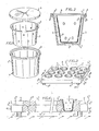
- the pot 1 in which is engaged the string 2 while a cover 3 ensures the closure of the assembly.
- the pot 1 has internally in its bottom l 1 a boss l 2 on which bears the lower part 2 1 of the dish.
- the pot has in its upper part a collar 1 3 in which engages the lips 3 - 3 2 of the cover 3.
- This collar l 3 is slightly offset towards the outside with respect to the peripheral wall l 4 of the pot so as to define a horizontal crown l 5 authorizing the support of the upper peripheral edge 2 2 of the dish.
- it has in the central part of the aforementioned border a peripheral centering bead 2 3 coming to bear after engagement of the dish in the pot against the inner wall 1 6 thereof.
- trays 4 are used which consist of two elements respectively defining an upper support 5 and a lower support 6.
- the trays thus formed and illustrated in particular in FIGS. 3 and 4 have on their surface and in their thickness a series of openings preferably arranged in rows in which the empty dishes are engaged by a mechanical process 2.
- suitable openings 5 1 and 6 1 are provided on each of the abovementioned supports 5 - 6, and are shaped according to the external shape of the crockery.
- Each dish comes to bear by its bead 2 3 on the visible part 5 2 of the support 5, and is flush with its bottom with the visible part 6 2 of the lower support 6 ( Figure 4).
- FIG. 3 illustrates, by way of example, a method of positioning the rows of dishes.
- the dishes are flush with each other to limit as much as possible areas of unused trays.
- the upper support 5 has on its lower face 5 3 protruding parts 5 4 distributed over the surface of the plate and coming to adjust ter in recesses 6 3 with complementary shapes established on the upper face 6 2 of the lower support 6, so as to ensure their assembly and prevent the mobility of the upper support relative to the lower support.
- the latter also has a base 6 4 and on its transverse edges 6 5 handles 6 6 for gripping or the like.
- the upper support has, from its lateral edges 5 5, a chamfer forming a lower ramp 5 6 , thus making a cavity 7 appear, along the sides of the supports in combination with the lateral edge of the lower support. , whose interest will appear later.
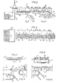
- a series of plates 4 mounted in superposition and in alignment are placed in a large capacity tank 8; the base 6 4 disposed on the lower support of a first plate bears on the apparent horizontal wall 5 2 of the upper support constituting the second plate and so on, showing between two superposed plates an interval e corresponding in fact to the base height 6 4 .
- the set of trays 4 is suitably positioned inside the tank 8.
- the tank is then filled with rennet milk and the like by means of a suitable dispenser and not illustrated.
- the milk thereby fills each of the dishes thanks in particular to the interval e authorizing the circulation of the fluid between two trays 4 superimposed.
- fastening elements integral with the lifting element 9 adjust on the handles 6 of the lower support and allow, under the actuation of the lifting element, the gripping and the movement of the plates 4 successively up to 'to a conveyor belt 10 controlled to move by an appropriate motor means (phase I).
- phase I a conveyor belt 10 controlled to move by an appropriate motor means
- the trays 4 are automatically advanced by means of the conveyor belt 10, being in abutment against each other until a second phase of treatment II.
- This second phase consists in causing the separation of the elements 5 and 6 constituting each plate 4.
- at least two guide rails 11 are provided, the ends 11 1 of which are bevelled to progressively engage in the cavity 7 and cooperate with chan brake 5 6 forming a ramp established on the edge of the lateral side of the upper support thereby causing the gradual separation of the elements 5 and 6.
- the rails 11 have an L-shaped profile 11 2 and are arranged on either side of the sides of the plate, the latter coming to bear by its longitudinal edges on the said rails. In fact, the position of the rails depends on the importance and the location of the areas of plates having no openings for the positioning of the dishes.
- the ends 11 1 of the rails 11 are situated slightly above the end of the treadmill 10.
- the rails themselves are arranged at a raised level by a height corresponding at least to the thickness of the lower support.
- the rails II are suitably positioned so that they engage longitudinally between two consecutive longitudinal rows of dishes. As illustrated in FIG. 5, when the upper support of a tray is fully engaged and resting on the guide rails I1, the lower support 6 is conveyed by means of a conveyor belt 12 to a cleaning station.
- the upper support 5 is supported on the rails 11, while the solid plates 2 are supported and suspended on the upper face 5 2 of said support their lower part projecting from below. It should be noted that the length of the rails is less than the length of the plates so that it is the consecutive supports 5 which cause the displacement of the upper support 5 preceding them on the rails.
- phase IV as illustrated in FIG. 9, the other ends 11 4 of the aforementioned rails come to bear or substantially against a treadmill 13.
- the thrust of the supports 5 causes the engagement of the first support in progressive support on the treadmill 13. From this fact, the dishes 2 are readjusted in position relative to the support 5, their upper part becoming free, and their lower part pressing on the treadmill 13.
- phase V the upper support and the dishes are advanced to this position.
- phase VI is the separation of the dishes 2 with respect to the support 5.
- a second series of guide and suspension rails 15 are provided, arranged at a level slightly above the level d 'a conveyor belt 14, so as to engage between the consecutive rows of dishes 2.
- the ends 15 1 of the rails extend beyond the end of the carpet 13 so that the dishes are gradually coming to bear by their bead 3 in engagement and suspended on the rails.
- the latter is conveyed to a cleaning station by means of conveyor belt 16.
- the number of rails is twice the number of dishes arranged in lateral rows, as illustrated in figure 8.
- phase VII we proceed to the advancement in this position of the dishes in combination possibly with other guidance and advancement means.
- the dishes are positioned in the pots 1.
- the latter are conveyed in an appropriate manner by a conveyor belt 18 to a station 19 onto which the guide rails and the suspension of the dishes flow from above. These fall in successive rows while being guided by appropriate means in the pots from being positioned in the manner described above.
- the assembly is then routed for other operations, such as positioning the cover, etc.
- the invention is in no way limited to that of its modes of application any more than to those of the embodiments of its various parts which have been more particularly indicated; on the contrary, it embraces all its variants.
Landscapes
- Life Sciences & Earth Sciences (AREA)
- Animal Husbandry (AREA)
- Environmental Sciences (AREA)
- Dairy Products (AREA)
Applications Claiming Priority (2)
| Application Number | Priority Date | Filing Date | Title |
|---|---|---|---|
| FR8009051 | 1980-04-17 | ||
| FR8009051A FR2480561A1 (fr) | 1980-04-17 | 1980-04-17 | Dispositif autorisant la mise en oeuvre automatique et industrielle de la fabrication et de la mise en pot de produits laitiers, notamment de fromages frais |
Publications (1)
| Publication Number | Publication Date |
|---|---|
| EP0038766A1 true EP0038766A1 (fr) | 1981-10-28 |
Family
ID=9241232
Family Applications (1)
| Application Number | Title | Priority Date | Filing Date |
|---|---|---|---|
| EP81420058A Withdrawn EP0038766A1 (fr) | 1980-04-17 | 1981-04-16 | Dispositif automatique autorisant la mise en pot de produits laitiers, tels que fromages frais |
Country Status (2)
| Country | Link |
|---|---|
| EP (1) | EP0038766A1 (enExample) |
| FR (1) | FR2480561A1 (enExample) |
Cited By (1)
| Publication number | Priority date | Publication date | Assignee | Title |
|---|---|---|---|---|
| EP1747728A1 (de) * | 2005-07-26 | 2007-01-31 | Hassia Verpackungsmaschinen GmbH | Verfahren zur verbrauchsfertigen Verpackung von Speisequark |
Families Citing this family (2)
| Publication number | Priority date | Publication date | Assignee | Title |
|---|---|---|---|---|
| ES8501603A1 (es) * | 1982-09-29 | 1984-12-01 | Derode Bernard | Un metodo y un aparato para tratar queso |
| FR2533411B1 (fr) * | 1982-09-29 | 1990-12-14 | Derode Bernard | Procede, dispositif et table pour fabriquer les fromages a pate fraiche ou a pate molle |
Citations (6)
| Publication number | Priority date | Publication date | Assignee | Title |
|---|---|---|---|---|
| FR1313172A (fr) * | 1961-11-13 | 1962-12-28 | Procédé de fabrication de fromages à pâte molle | |
| FR1332744A (fr) * | 1962-06-09 | 1963-07-19 | Bastert Werke Gustav Bastert | Procédé et appareil pour la mise en godets de produits dégageant de l'eau, notamment de fromages en couches superposées et de fromage blanc |
| FR1527855A (fr) * | 1967-03-02 | 1968-06-07 | Laitiere Du Forez Soc | Conditionnement pour fromages blancs |
| FR2045236A5 (en) * | 1969-06-26 | 1971-02-26 | Chanet Jacques | Cheese mould |
| FR2082779A5 (en) * | 1970-03-26 | 1971-12-10 | Entremont Marcillat | Automatic cheese-making plant - contg many conveyors |
| GB1423958A (en) * | 1974-10-30 | 1976-02-04 | Crockatt Sons Ltd W | Automatic chisset remover |
-
1980
- 1980-04-17 FR FR8009051A patent/FR2480561A1/fr active Granted
-
1981
- 1981-04-16 EP EP81420058A patent/EP0038766A1/fr not_active Withdrawn
Patent Citations (6)
| Publication number | Priority date | Publication date | Assignee | Title |
|---|---|---|---|---|
| FR1313172A (fr) * | 1961-11-13 | 1962-12-28 | Procédé de fabrication de fromages à pâte molle | |
| FR1332744A (fr) * | 1962-06-09 | 1963-07-19 | Bastert Werke Gustav Bastert | Procédé et appareil pour la mise en godets de produits dégageant de l'eau, notamment de fromages en couches superposées et de fromage blanc |
| FR1527855A (fr) * | 1967-03-02 | 1968-06-07 | Laitiere Du Forez Soc | Conditionnement pour fromages blancs |
| FR2045236A5 (en) * | 1969-06-26 | 1971-02-26 | Chanet Jacques | Cheese mould |
| FR2082779A5 (en) * | 1970-03-26 | 1971-12-10 | Entremont Marcillat | Automatic cheese-making plant - contg many conveyors |
| GB1423958A (en) * | 1974-10-30 | 1976-02-04 | Crockatt Sons Ltd W | Automatic chisset remover |
Cited By (1)
| Publication number | Priority date | Publication date | Assignee | Title |
|---|---|---|---|---|
| EP1747728A1 (de) * | 2005-07-26 | 2007-01-31 | Hassia Verpackungsmaschinen GmbH | Verfahren zur verbrauchsfertigen Verpackung von Speisequark |
Also Published As
| Publication number | Publication date |
|---|---|
| FR2480561A1 (fr) | 1981-10-23 |
| FR2480561B1 (enExample) | 1982-04-23 |
Similar Documents
| Publication | Publication Date | Title |
|---|---|---|
| FR2512780A1 (fr) | Conteneur emboitable et gerbable | |
| EP0038766A1 (fr) | Dispositif automatique autorisant la mise en pot de produits laitiers, tels que fromages frais | |
| FR2490589A1 (fr) | Procede et appareil de remplissage de recipients | |
| FR2659593A1 (fr) | Dispositif pour la fabrication automatique de produits en beton moule necessitant un demoulage par retournement. | |
| EP0736247A1 (fr) | Claies pour fabrication de fromage, procédé de fabrication de fromage mettant en oeuvre de telles claies et dispositif de retournement d'une pile de telles claies | |
| EP0263024B1 (fr) | Dispositif perfectionné de démoulage et de manutention des produits en béton coulés en moules fixes | |
| EP0559584B1 (fr) | Bloc-moule pour la fabrication de fromages | |
| FR2468299A1 (fr) | Procede et appareil pour cultiver des plantes | |
| FR2613583A1 (fr) | Procede et machine pour le remplissage d'un ensemble de moules destines a la fabrication de fromages | |
| EP0244330B1 (fr) | Moules à fromage empilables et retournables | |
| EP0352165B1 (fr) | Dispositif de moulage et retournement automatique de moules contenant du caillé | |
| EP3780949B1 (fr) | Installation de moulage de caillé pour la fabrication de fromage | |
| FR2470534A1 (fr) | Machine a demouler et a rogner des fromages | |
| EP3532389B1 (fr) | Procédés et dispositifs de remplissage de pots, lignes de conditionnement de pots | |
| FR3112921A1 (fr) | moule pour le formage d’une meule de Comté et procédé de formage d’une telle meule | |
| FR2697512A1 (fr) | Procédé de chargement sur un support de regroupement d'articles amenés au moins sensiblement en continu et dispositif en vue de la mise en Óoeuvre de ce procédé. | |
| FR2779318A1 (fr) | Procede pour le moulage modulable d'un melange de caille et de serum et dispositif | |
| EP1050210A1 (fr) | Dispositif de moulage d'un mélange de caillé et de sérum, installation de fabrication de fromages, procédé de moulage et procédé de fabrication de fromages correspondants | |
| FR2595199A1 (fr) | Procede et dispositif pour le remplissage simultane de plusieurs moules a fromage avec des quantites dosees de caille | |
| EP1088479A1 (fr) | Support d'égouttage pour la fabrication de fromages | |
| FR2626808A1 (fr) | Procede et dispositif pour la mise en place automatique d'une armature dans un moule propre a recevoir une matiere coulable telle que du beton | |
| FR2555017A1 (fr) | Dispositif de pressage avec possibilite de retournement pour la fabrication de fromages | |
| FR3130115A1 (fr) | Table d’égouttage pour la fabrication de fromages et Installation mécanisée comprenant une telle table d’égouttage et des plateaux d’égouttage roulants | |
| FR2551693A1 (fr) | Machine automatique a demouler des produits, en particulier des jambons | |
| FR2531406A1 (fr) | Perfectionnements a des bacs moules empilables |
Legal Events
| Date | Code | Title | Description |
|---|---|---|---|
| PUAI | Public reference made under article 153(3) epc to a published international application that has entered the european phase |
Free format text: ORIGINAL CODE: 0009012 |
|
| AK | Designated contracting states |
Designated state(s): AT BE CH DE GB IT LU NL SE |
|
| 17P | Request for examination filed |
Effective date: 19811117 |
|
| STAA | Information on the status of an ep patent application or granted ep patent |
Free format text: STATUS: THE APPLICATION IS DEEMED TO BE WITHDRAWN |
|
| 18D | Application deemed to be withdrawn |
Effective date: 19830606 |
|
| RIN1 | Information on inventor provided before grant (corrected) |
Inventor name: DUMAS, ROLAND |