EP0038672A2 - Circuits de commande pour machines à laver et machines analogues ou pour d'autres appareils - Google Patents
Circuits de commande pour machines à laver et machines analogues ou pour d'autres appareils Download PDFInfo
- Publication number
- EP0038672A2 EP0038672A2 EP81301660A EP81301660A EP0038672A2 EP 0038672 A2 EP0038672 A2 EP 0038672A2 EP 81301660 A EP81301660 A EP 81301660A EP 81301660 A EP81301660 A EP 81301660A EP 0038672 A2 EP0038672 A2 EP 0038672A2
- Authority
- EP
- European Patent Office
- Prior art keywords
- programme
- control circuit
- functional
- washing
- machine
- Prior art date
- Legal status (The legal status is an assumption and is not a legal conclusion. Google has not performed a legal analysis and makes no representation as to the accuracy of the status listed.)
- Withdrawn
Links
Images


Classifications
-
- G—PHYSICS
- G05—CONTROLLING; REGULATING
- G05B—CONTROL OR REGULATING SYSTEMS IN GENERAL; FUNCTIONAL ELEMENTS OF SUCH SYSTEMS; MONITORING OR TESTING ARRANGEMENTS FOR SUCH SYSTEMS OR ELEMENTS
- G05B19/00—Programme-control systems
- G05B19/02—Programme-control systems electric
- G05B19/04—Programme control other than numerical control, i.e. in sequence controllers or logic controllers
- G05B19/048—Monitoring; Safety
-
- D—TEXTILES; PAPER
- D06—TREATMENT OF TEXTILES OR THE LIKE; LAUNDERING; FLEXIBLE MATERIALS NOT OTHERWISE PROVIDED FOR
- D06F—LAUNDERING, DRYING, IRONING, PRESSING OR FOLDING TEXTILE ARTICLES
- D06F34/00—Details of control systems for washing machines, washer-dryers or laundry dryers
- D06F34/08—Control circuits or arrangements thereof
-
- D—TEXTILES; PAPER
- D06—TREATMENT OF TEXTILES OR THE LIKE; LAUNDERING; FLEXIBLE MATERIALS NOT OTHERWISE PROVIDED FOR
- D06F—LAUNDERING, DRYING, IRONING, PRESSING OR FOLDING TEXTILE ARTICLES
- D06F37/00—Details specific to washing machines covered by groups D06F21/00 - D06F25/00
- D06F37/42—Safety arrangements, e.g. for stopping rotation of the receptacle upon opening of the casing door
Definitions
- This invention relates to a control circuit for controlling the supply of current from a source thereof to machines (hereinafter referred to as being of the kind specified) for subjecting articles to treatment involving a liquid, which machines include a plurality of functional devices energised for operation by such current.
- the invention has been developed primarily for application to machines for washing clothes and other articles and dish washing machines for washing plates, cuttlery etc. and other items of tableware, each such machine comprising a body, including a chamber in which the articles can be placed for treatment, a plurality of functional means for performing respective functions during a treatment programme, and including means for effecting transfer of the liquid to and from the chamber so that it is brought into contact with, and removed from, the articles, and means for subjecting at least either the liquid or the articles to motion whilst both are in the chamber, said functional means being each electrically controlled or operated.
- one application of the invention is to a specific form of machine of the kind specified, namely a machine intended for washing clothes or other textile articles.
- the means for effecting transfer of liquid to and from the chamber will normally comprise valve means operative in supply ducts for the liquid and may also include pump means for assisting discharge of the liquid from the chamber.
- the means for subjecting either the liquid or the articles to motion may comprise either a drum defining the, chamber and which is mounted for rotation by a drive means such as an electric motor, or may comprise a paddle or impeller means for setting up flow patterns in the liquid whilst in the chamber.
- the means for effecting transfer of the liquid to and from the chamber may again be in the form of valve means operative in one or more ducts and may further comprise pump means for effecting discharge of the liquid from the chamber.
- the means for subjecting either the liquid or the articles to relative motion may comprise a further pump means operating in conjunction with a liquid delivery nozzle movable or otherwise for directing the liquid onto the articles to be washed and/or may further comprise means for rotating a drum, container or holder in which such articles are supported.
- the inputs to the subordinate control circuit and which control the sequence of their operation, and hence the sequence of the operation of the functional means, have heretofore been provided by the outputs of an integrated semi-conductor unit, the architecture of which has been specifically designed for a particular application, e.g. a-particular series of washing machines to be produced.
- a control circuit in or for machines of the kind specified, said control circuit comprising programming means, adapted to furnish control signals in accordance with a selected programme to a plurality of electrically energised functional means for performing respective operations in accordance with said selected programme characterised in that said programming means includes a test programme, said test programme being adapted to accelerate the rate of performance of at least some of the functional means.
- the machine may be tested prior to sale in an efficient and hence economical manner. Furthermore, if a fault occurs during use of the machine, the time in which the fault can be found and corrected is considerably decreased due to the possibility of testing via the test programme, the functional parts of the machine at a greater rate than has in the past been possible.
- said control circuit further comprises sensing means adapted to sense the performance of said functional means at least during said test programme, said sensing means being adapted to provide a fault signal on occurrence of one of said functional means operating in an incorrect manner.
- control circuit further comprises indicating means adapted to indicate the presence of a fault and, in a preferred embodiment, said indicating means is adapted to indicate the nature of the fault in as much as it provides information relating to which of the functional means is not operating correctly.
- said sensing means and said indicating means may be adapted to provided sensing of the functional means and indication of a fault should it occur during the normal programmes which the machine is adapted to perform.
- control circuit programming, and sensing means (or a substantial part of each of these means) be incorporated to form part of a micro processor.
- This enables the testing and the fault indicator facility to be provided economically in comparison with what would be possible by the use of a purpose designed integrated circuit unit and a plurality of "hard wired" subordinate circuits each associated with, and forming part of, a particular one of the functional means.
- There may nevertheless be some hard wired components in sub-circuits associated with and forming part of respective functional means, although the preponderance of the electrical functions to be performed would be carried out and in and by the micro processor.
- a further preferred feature of the invention is that the sensing means continually monitors the performance of at least some of the functional means concerned during a normal programme, and in the case of a fault occurring, if necessary stops the programme, the indicating means indicating the nature of the fault.
- the bringing of test programme into operation is effected by means of a switch or other means which is of a character, or is so located in the control circuit or-apparatus, as not to form a normal user's control (it may be confined to use by service personnel), for example by mounting the switch or other control means for the test programme in a compartment or at a location in the machine to which access can be had only through an openable closure member normally retained in its closed position under the control of a lock.
- a single drive motor may be utilised and caused to operate the respective drive means in different modes or at different speeds.
- the drive motor may be rotated successively in opposite rotational senses for establishing washing action and for establishing distribution of the articles for centrifugal extraction of the washing liquid may be rotated unidirectionally and at a speed higher than the speed involved in the washing action.
- the apparatus may further include a plurality of electrically energised functional means for performing respective operations in accordance with the programme or any one of a plurality of programmes, a control circuit comprising:
- the set of indicator elements may be arranged 'to provide both the number or other identifying symbol of the wash programme selected, and the character of a fault responsive to generation of a fault signal by the sensing means.
- respective indicator elements may be arranged to provide the number or other identifying symbol of a plurality of optional features of the selected wash programme actually selected, and the character of a fault.
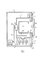
- the washing machine illustrated comprises a body which includes a stationary washing chamber 1 which may be of generally cylindrical form containing a washing drum 2 rotatable about a horizontal axis, the washing chamber being supported in any suitable manner, for example by struts 3 from a base 3a.
- a stationary washing chamber 1 which may be of generally cylindrical form containing a washing drum 2 rotatable about a horizontal axis, the washing chamber being supported in any suitable manner, for example by struts 3 from a base 3a.
- a casing 4 encloses the washing chamber and drive means for the drum which comprises a motor 12c which drives the drum spindle 2a through the intermediary of a belt and pulley drive 9.
- the spindle 2a and the drum is supported by a suitable bearing 8 carried by the washing chamber.
- the washing chamber has a plurality of inlets, for example hot water inlet controlled by a solenoid valve 12e,. a cold water inlet controlled by a solenoid valve 12g and a drain outlet preferably communicating with a well or sump in the washing chamber and controlled by an electrically driven pump 12b.
- the washing chamber 1 is sealed with respect to the casing by a flexible gasket or sealing ring 6 and the entrance to the washing chamber 1 and drum 2 is controlled by a door 5 which is hingedly connected to the casing 4 about a vertical axis 7 and is movable upon release of a solenoid controlled door lock 12a between the closed. position shown and an open position.
- a sealing ring or gasket 5 Associated with the door is a sealing ring or gasket 5 operative between the door and the casing.
- a further functional unit seen in Figure 1 is a heater 12d for heating the liquid in the washing chamber.
- Other electrically energised functional units are omitted from Figure 1 merely for the sake of simplicity and may include a solenoid operated conditioner valve controlling the flow of conditioning liquid through a duct into the washing chamber.
- the electrically energised functional units are identified at 12a to 12g.
- the supply of current to these units from a 240 volt alternating current mains is connected to the input terminals t1, t2 of a main manually operable isolator switch S1, the output terminals t3, t4 of which are connected to the primary winding of power supply transformer T1 and also to power supply rails 15 and 16, in the latter case through the intermediary of a switch S2 operated by door release splenoid 12a.
- the supply of current to the functional units 12a to 12g from the conductors 15 and 16 is controlled by respective gate controlled semi-conductor devices 13a to 13g respectively in accordance with the output signals developed at the outlets of control circuits incorporating a micro processor 10 and designated 10a to 10g respectively.
- control circuits incorporating a micro processor 10 and designated 10a to 10g respectively In the case of functional units 13b to 13g these outputs are fed through the intermediary of an output driver 17.
- supplementary devices which control or contribute to the function performed by the functional devices, these being high, medium and low level switches S3, S4, S5 serving respectively to control current to the hot water solenoid valve 12e, cold water solenoid valve 12f and heater 12d and which provide inputs to the micro processor at terminals 10k, 101, 10m to control the liquid levels in the drum.
- a further supplementary device is a tacho generator 12c 1 operatively coupled mechanically as indicated by the broken line 12c 2 to drive motor 12c and providing an input to the micro processor at terminal 10n.
- a further supplementary device is a thermistor Th 1 which senses the temperature of the washing liquid in the washing chamber and provides an input to the micro processor at terminal 10p.
- the direction of energisation of the field winding F of the drive motor 12c is controlled by a further supplementary device, namely a relay RV having reversing contacts S6 and powered from secondary winding T1c, transformer T1 (44 volts).
- the relay RV is operated under the control of the output at micro processor terminal 10i.
- the magnitude of the current in the motor is controlled by the output at terminal 10c of the micro processor 10 and current supply to the,motor is isolated by a master .
- relay MR having switch contacts S7.
- a series of switches preferably of the press button type, S8a to S8i provide inputs at terminals 11a to 11i respectively for initiating the following programmes or operations, namely cancel, open door, rinse hold, test, half load, bio, prewash, start, and programme, the significance of which is explained hereinafter.
- Indicator means 14 comprising a plurality of electrically energisable indicator elements, for example light emitting diodes 14a - 14g which constitute a 7 segment numerical indicator and elements 14h - 14m which consist of single light emitting diodes, both sets of light emitting diodes being controlled by outputs at terminals 13a - 13g of the micro processor through the intermediary of a display power driver.
- the two sets of display elements, namely 14a - 14g and 14h - 14m are each supplied respectively by alternate half cycles of the A.C. electricity supply from transformer secondary T1b via diodes 19a and 19b.
- the programming provided by the micro processor 10 is such that certain of the display elements provide different classes of information at stages of operation of the machine.
- the single L.E.D.'s 14h - 14m indicate options for selection whilst the LED's 14a - 14g providing the seven segment numerical indicator will indicate the identification number of the wash programme.
- the seven segment numerical indicator display is then used to indicate this fact by flashing alternatively 'F' and a code number signifying the nature of the fault.
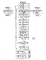
- micro processor 10 The architecture of the micro processor 10 is most conveniently comprehended by reference to the flow diagrams shown in Figures 3, 4 and 5 before referring to the former of these it is convenient briefly to refer to the setting up of the machine by the operator to carry out the required programme as follows.
- the flow diagram of Figure 3 represents graphicaly the complete set of sub-routines provided by the micro processor.
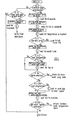
- Figure 6 is a similar flow diagram representing the programme which provides fault indication.
- Blocks with round ends designate Start or Stop operations
- ' rectangular blocks designate non-decision operations which are carried out
- diamond-shaped blocks designate interrogations to determine the route which will be determined by the programme
- the various options selected and circular blocks designate exits to await actions by the functional units to be controlled and circuitry external to the micro processor.
- This routine has three parts:-
- This routine is accessed automatically at power on and clears all registers or outputs to the correct quiescent state. It is used in the event of a cancel from the facia or partially at the end of a main wash programme.
- the basic subroutines of the general programme are repeated every half cycle of the 50 Hz mains commencing with synchronisation to the zero crossing point.
- no wash programme is running the general subroutines are scanned but no actions are initiated.
- the displays are updated but no other data is accessed until the start button is pressed.
- the main wash programme is accessed and proceeds to the first exit point.
- the programme then returns to the basic loop, synchronises to 50 Hz and scans through the action subroutines updating any changes.
- the programme jumps back to the exit point checks to see if the action under operation is complete. If not complete the programme repeats the loop just described until complete.
- the wash programme then proceeds to the next exit point and the same sequence is repeated through to the end of the programme.
- the action routines fill, heat, motor
- they have inherent fault checks so that should any hazard arise the whole sequence is terminated, all actions turned off and the appropriate fault code displayed. The only exception to this is the pump failure which would be detected prior to a spin cycle in the rinse section of the main wash control programme.
- the programme selection is effected by means of a single control (button), e.g. S8i, which is held in its operated position until the required programme number, letter or other designation appears on a seven segment numerical indicator, e.g. indicator element 14a - 14g.
- a totally blank display indicates power off or controller failure.
- a momentary depression of the start push-button control S8b starts the selected programme sequence, isolates all functional setting buttons other than "Start” (used to clear Rinse hold) and cancel (used to cancel the sequence if required), and effects transfer of function of the indicator means 14h - 14m from indicating programme options to indicating programme progress. For example, if in selecting the programme the control marked "Bio" is depressed an indicator element, e.g. 14k, will be illuminated but once the Start button has been depressed the indicator elements 14h - 14m will be illuminated in sequence to designate the following stages, namely Heat, Wash, Rinse 1, Rinse 2, Rinse 3 and End.
- the pre-wash programme can be selected alone or prior to any of the other programmes except Test or Spin only. It is selected by operation of push-button S8c and indicated by indicator element 141 (prior to depression of the Start button). If selected with Rinse and Spin it modifies the wash action and duration, and spin speed and duration but does not add pre-wash before the Rinse and Spin cycle.
- the door is mechanically locked by a solenoid release latch. Energisation of the solenoid 12a occurs only if
- the door release solenoid is energised via the off contact of the low level switch S5 and the door switch S2 and thus can be energised only long enough to release the door lock mechanism.
- An indication "door may be opened” is provided by one of the indicator elements, e.g. 14h, which is energised continuously,i.e.providing a steady illumination, before any programme is selected and is energised intermittently, i.e. providing flashing illumination, after a programme has been completed but before the door has been opened once. The opening of the door effects resetting of the control so that these are ready to select another programme.
- Operation of the push-button S8h causes immediate cancellation of data before the Start button S8b is pressed and has to be held in the operated position for a predetermined period, e.g. 2.5 seconds, before it will effect cancellation of a running programme.
- a predetermined period e.g. 2.5 seconds
- Direct connection to the outlet 10b controlling the semi-conductor device 13b for the pump 12b allows the pump to be operated independently under any conditions when the power is on.
- the indicator elements namely 14h to 14m, are used at different stages to provide indication of different characters.
- the first is to indicate programme progress and the devices are energised respectively in sequence to indicate progression of Heat, Wash, Rinse 1, Rinse 2, Rinse 3 and End of a programme.
- indicator elements applicable to the heat part of the programme and the wash part of the programme are energised cylically until the heat and wash parts of the programme are completed, i.e. heat, wash for bio or pre-wash, then blank followed by heat, wash for the main wash programme.
- this programme is basically a pre-wash with hot and cold high fill and a hold at the end of a 10 minute wash cycle. During the hold, action is limited to one wash action every 10 minutes, the wash action typically occupying 30 seconds. To end the soak period the start button is pressed. The machine then pumps out and automatically continues with three rinses and a 2 minute slow spin. Any option other than rinse hold may be added to the programme. Bio gives a 20 minute gentle wash at 30 C followed by the soak. Pre- wash and half load operate normally.
- the indicator elements energised in sequence during the soak programme and Heat 14m, Wash 141 followed by the three rinse indicator elements 14k to 14i. During soak the indicator elements 14m and 141 are permanently energised and indicator element 14i flashes on and off once per second.
- washing programmes which can be provided under the control of the micro processor, the latter is an example of such a programme.
- reference to “fill cold” and “fill hot” includes the addition of a washing powder or detergent as required.
- action means rotation of the drum firstly in one direction and then in the other.
- the reference to “pump spin” means operation of the discharge pump accompanied by spinning of the drum.
- fill cold means filling with cold water not accompanied by any detergent.
- the programme includes a wash sequence (as defined in sub-paragraph 1 above) in which the action for wash is continued for periods which are typically 5 to 12 minutes and thereafter three rinse sequences follow as typically specified in sub-paragraphs 2 to 4 inclusive.
- the micro processor is also adapted to perform a test programme in which programme the rate of performance of the various functional units of the machine is considerably accelerated.
- FIG. 6 A flow diagram illustrating the test programme is shown in Figure 6 and the,sequence of operations are as follows.
- An open circuit heater or short circuit heater triac would be indicated by fault code F6 when the low level is reached.
- F6 at switch on indicates no power to the level switch or open circuit low level input.
- An open circuit or short circuit thermister is indicated by fault code F1 at the end of the test programme. Any fault occurring between heat and the end will override a thermistor fault.
- F5 indicates failure to heat, most probable cause would be open circuit heater triac. This takes 30 minutes to occur on 30°C, 40°C, 50°C, programmes and 1 hour on the 60°C and 85°C programmes.
- the fault codes F1 to F6 above referred to are indicated by energisation of respective indicator elements, e.g. 14a to 14g of the. seven segment display.
- the total time for the test sequence depends on water pressure and inlet temperature of the hot water but is approximately 10 minutes.
- test programme may be brought into effect by operation of a control such as a push-button switch which may or may not be accessible to the muser of the machine if it is intended that the test programme should be solely for the use of experienced service personnel.
- a control such as a push-button switch which may or may not be accessible to the muser of the machine if it is intended that the test programme should be solely for the use of experienced service personnel.
- the micro processor may be so programmed to disconnect the supply to the machine or otherwise render the machine inoperative and in a safe condition.
- the speed is sensed by a tacho generator providing an electrical output dependent on the speed of revolution of the motor.
- the micro processor can be programmed such that the output from said tacho generator is compared with a stored signal and if at any required speed, for example tumbling speed, slow spin speed, high spin speed, the signal obtained from the tacho generator does not correspond with the stored signal then a fault will be displayed by the indicating means.
- the water temperature sensor may comprise.a thermostat or a plurality of thermostats adapted to open or close at predetermined temperatures.
- the state of said thermostat or thermostats i.e. whether* it is open or closed, will be registered by the micro processor and compared with a predetermined expected state at a particular time in the programme and, once again if the state of the thermostat does not comply with the expected state, a fault signal may be displayed.
- thermo-resistor An alternative method of sensing water temperature would be to provide a device such as a thermister, the electrical resistance of which changes in accordance with the temperature of its surroundings, in this case the water within the drum and the current passing in a circuit through the thermo-resistor would accordingly be varied.
- the current may be monitored by the micro processor preferably after having been converted to a digital signal and the expected value of said current compared with predetermined values at different stages during the programme.
- the height of water level within the drum may be monitored by a pressure switch adapted to open or close at a predetermined water level height.
- a pressure switch adapted to open or close at a predetermined water level height.
- the water temperature sensing means themselves may be tested by sensing the rate of temperature change sensed by the water temperature sensors, for example a thermistor. Provided the heater is working satisfactorily, for a constant volume of water, the rate of temperature change between two set values will be a known value apart from minor variations caused by outside influences such as ambient temperature. If, therefore, the rate of change is significantly different and, the value is compared with an expected value, the fault signal may be provided in which Fault is displayed on the indicating means.
- Means for testing operation of the pump may include a further tachometer, if the pump is driven by its own motor, the sensing of the value provided by the tachometer and issue of a fault signal being as afore described with reference to the motor operation for driving the drum.
- micro processors In order to determine the nature of the fault, and in particular which functional unit is operating incorrectly, it is necessary for the micro processor to compare the signals from various sensors and isolate the . faulty functional unit.
- the ability of micro processors to receive and compare signals and store the result therefrom renders them highly suitable for inclusion in the control circuit of the present invention.
- a machine could operate in accordance with the present invention using a conventional electro-mechanical programmer in which a plurality of switches are operated in sequence by rotary switch or cam means rotating on a shaft.
- the shaft is rotated by a motor at a low speed and in this case switching means may be provided to isolate the switching means used in a normal programme and bring into operation separate switches in which the rate of performance of the functional units is accelerated.
- switching means may be provided to isolate the switching means used in a normal programme and bring into operation separate switches in which the rate of performance of the functional units is accelerated.
- a conventional,programme may last for half an hour being the time taken for one complete revolution of an electro-mechanical programmer
- a set of switches may be provided all of which are operated within 10 minutes, the switches however bring into operation the majority or all the functional units of the machine for the purposes of testing their performance.
- the means for monitoring the performance of the various functional units may be as afore described and in the case of the correct operation of the motor may comprise a tacho generator using an output dependent on speed of revolution of the motor, in the case of the water temperature may comprise thermostats or thermistors, pressure switches detecting the level of water within the drum and the- current supplied to the heater element also being monitored.
- test programme may be brought into effect by operation of a control such as a push-button switch not excessible to the user. It provides two facilities. ,
Applications Claiming Priority (2)
| Application Number | Priority Date | Filing Date | Title |
|---|---|---|---|
| GB8012557 | 1980-04-16 | ||
| GB8012557A GB2079976B (en) | 1980-04-16 | 1980-04-16 | Operation of a programme controlled machine in the event of a fault |
Publications (2)
| Publication Number | Publication Date |
|---|---|
| EP0038672A2 true EP0038672A2 (fr) | 1981-10-28 |
| EP0038672A3 EP0038672A3 (fr) | 1982-06-16 |
Family
ID=10512828
Family Applications (1)
| Application Number | Title | Priority Date | Filing Date |
|---|---|---|---|
| EP81301660A Withdrawn EP0038672A3 (fr) | 1980-04-16 | 1981-04-15 | Circuits de commande pour machines à laver et machines analogues ou pour d'autres appareils |
Country Status (8)
| Country | Link |
|---|---|
| EP (1) | EP0038672A3 (fr) |
| AU (1) | AU6948581A (fr) |
| CA (1) | CA1155528A (fr) |
| DK (1) | DK174281A (fr) |
| ES (1) | ES8300900A1 (fr) |
| GB (1) | GB2079976B (fr) |
| IE (1) | IE51087B1 (fr) |
| NO (1) | NO811324L (fr) |
Cited By (6)
| Publication number | Priority date | Publication date | Assignee | Title |
|---|---|---|---|---|
| DE3146566A1 (de) * | 1981-11-24 | 1983-06-01 | Bosch-Siemens Hausgeräte GmbH, 7000 Stuttgart | Verfahren zum ueberwachen der funktionstuechtigkeit von funktionselementen in einem haushaltgeraet |
| EP0333233A2 (fr) * | 1986-01-22 | 1989-09-20 | Nordson Corporation | Méthode de détection du mauvais fonctionnement des circuits de chauffage dans un système de chauffage pour colles thermofusibles à plusieurs composants |
| EP0820718A2 (fr) * | 1996-07-26 | 1998-01-28 | SHARP Corporation | Lave vaisselle pour laver les assiettes à panier de lavage tournant et panier de lavage correspondant |
| EP1186695A3 (fr) * | 2000-09-12 | 2004-04-28 | Kabushiki Kaisha Toshiba | Commande à distance pour appareil de traitement du linge |
| EP2857570A1 (fr) * | 2004-12-02 | 2015-04-08 | Samsung Electronics Co., Ltd | Procédé pour l'élimination des plis dans le linge inclu dans un tambour d'une machine à laver |
| CN111593530A (zh) * | 2019-02-20 | 2020-08-28 | 青岛海尔洗衣机有限公司 | 一种洗衣机的控制方法及洗衣机 |
Families Citing this family (3)
| Publication number | Priority date | Publication date | Assignee | Title |
|---|---|---|---|---|
| US4546646A (en) * | 1982-10-01 | 1985-10-15 | Fuji Jukogyo Kabushiki Kaisha | System for diagnosing an internal combustion engine |
| GB2136601B (en) * | 1983-03-17 | 1987-11-18 | Hotpoint Ltd | Clothes washing and spin drying machines |
| GB8523282D0 (en) * | 1985-09-20 | 1985-10-23 | Hotpoint Ltd | Washing machines & control systems |
Citations (6)
| Publication number | Priority date | Publication date | Assignee | Title |
|---|---|---|---|---|
| US3662186A (en) * | 1969-06-27 | 1972-05-09 | Whirlpool Co | Electronic control circuit for appliances |
| DE2744694A1 (de) * | 1976-10-01 | 1978-04-06 | Servis Domestic Appliances Ltd | Steuerkreis zur steuerung der stromzufuhr, insbesondere fuer wasch- und trockenmaschinen o.dgl. |
| DE2949934A1 (de) * | 1978-12-18 | 1980-07-03 | Philips Nv | Geraet mit digitalem signalprozessor und funktionspruefmitteln |
| DE2948878A1 (de) * | 1978-12-18 | 1980-07-03 | Gen Electric | Wasch- oder geschirrspuelmaschine |
| FR2444966A1 (fr) * | 1978-12-18 | 1980-07-18 | Gen Electric | Circuit de commande a microprocesseur pour appareils de lavage |
| US4245309A (en) * | 1978-12-18 | 1981-01-13 | General Electric Company | Microprocessor based control circuit for washing appliances with diagnostic system |
-
1980
- 1980-04-16 GB GB8012557A patent/GB2079976B/en not_active Expired
-
1981
- 1981-04-13 AU AU69485/81A patent/AU6948581A/en not_active Abandoned
- 1981-04-13 IE IE835/81A patent/IE51087B1/en unknown
- 1981-04-15 DK DK174281A patent/DK174281A/da active IP Right Grant
- 1981-04-15 EP EP81301660A patent/EP0038672A3/fr not_active Withdrawn
- 1981-04-15 ES ES501428A patent/ES8300900A1/es not_active Expired
- 1981-04-15 NO NO811324A patent/NO811324L/no unknown
- 1981-04-15 CA CA000375609A patent/CA1155528A/fr not_active Expired
Patent Citations (9)
| Publication number | Priority date | Publication date | Assignee | Title |
|---|---|---|---|---|
| US3662186A (en) * | 1969-06-27 | 1972-05-09 | Whirlpool Co | Electronic control circuit for appliances |
| DE2744694A1 (de) * | 1976-10-01 | 1978-04-06 | Servis Domestic Appliances Ltd | Steuerkreis zur steuerung der stromzufuhr, insbesondere fuer wasch- und trockenmaschinen o.dgl. |
| GB1592759A (en) * | 1976-10-01 | 1981-07-08 | Servis Domestic Appliances Ltd | Control circuits in orfor washing drying and the like machines or other apparatus |
| DE2949934A1 (de) * | 1978-12-18 | 1980-07-03 | Philips Nv | Geraet mit digitalem signalprozessor und funktionspruefmitteln |
| DE2948878A1 (de) * | 1978-12-18 | 1980-07-03 | Gen Electric | Wasch- oder geschirrspuelmaschine |
| FR2444966A1 (fr) * | 1978-12-18 | 1980-07-18 | Gen Electric | Circuit de commande a microprocesseur pour appareils de lavage |
| GB2039677A (en) * | 1978-12-18 | 1980-08-13 | Philips Nv | Apparatus comprising a digital processor and function test means |
| US4241400A (en) * | 1978-12-18 | 1980-12-23 | General Electric Company | Microprocessor based control circuit for washing appliances |
| US4245309A (en) * | 1978-12-18 | 1981-01-13 | General Electric Company | Microprocessor based control circuit for washing appliances with diagnostic system |
Cited By (11)
| Publication number | Priority date | Publication date | Assignee | Title |
|---|---|---|---|---|
| DE3146566A1 (de) * | 1981-11-24 | 1983-06-01 | Bosch-Siemens Hausgeräte GmbH, 7000 Stuttgart | Verfahren zum ueberwachen der funktionstuechtigkeit von funktionselementen in einem haushaltgeraet |
| EP0333233A2 (fr) * | 1986-01-22 | 1989-09-20 | Nordson Corporation | Méthode de détection du mauvais fonctionnement des circuits de chauffage dans un système de chauffage pour colles thermofusibles à plusieurs composants |
| EP0333233A3 (en) * | 1986-01-22 | 1989-10-18 | Nordson Corporation | Method for detecting heater circuit malfunctions in a multi-component hot melt heating system |
| EP0820718A2 (fr) * | 1996-07-26 | 1998-01-28 | SHARP Corporation | Lave vaisselle pour laver les assiettes à panier de lavage tournant et panier de lavage correspondant |
| EP0820718A3 (fr) * | 1996-07-26 | 1999-04-21 | Sharp Kabushiki Kaisha | Lave vaisselle pour laver les assiettes à panier de lavage tournant et panier de lavage correspondant |
| EP1186695A3 (fr) * | 2000-09-12 | 2004-04-28 | Kabushiki Kaisha Toshiba | Commande à distance pour appareil de traitement du linge |
| US6778868B2 (en) | 2000-09-12 | 2004-08-17 | Kabushiki Kaisha Toshiba | Remote control of laundry appliance |
| EP2857570A1 (fr) * | 2004-12-02 | 2015-04-08 | Samsung Electronics Co., Ltd | Procédé pour l'élimination des plis dans le linge inclu dans un tambour d'une machine à laver |
| EP3333300A1 (fr) * | 2004-12-02 | 2018-06-13 | Samsung Electronics Co., Ltd. | Élimination des plis dans le linge |
| EP3524725A1 (fr) * | 2004-12-02 | 2019-08-14 | Samsung Electronics Co., Ltd. | Appareil et procede pour eliminer les rides dans des vetements |
| CN111593530A (zh) * | 2019-02-20 | 2020-08-28 | 青岛海尔洗衣机有限公司 | 一种洗衣机的控制方法及洗衣机 |
Also Published As
| Publication number | Publication date |
|---|---|
| AU6948581A (en) | 1981-10-22 |
| CA1155528A (fr) | 1983-10-18 |
| IE810835L (en) | 1981-10-16 |
| IE51087B1 (en) | 1986-10-01 |
| NO811324L (no) | 1981-10-19 |
| EP0038672A3 (fr) | 1982-06-16 |
| GB2079976B (en) | 1984-12-05 |
| ES501428A0 (es) | 1982-11-01 |
| DK174281A (da) | 1981-10-17 |
| GB2079976A (en) | 1982-01-27 |
| ES8300900A1 (es) | 1982-11-01 |
Similar Documents
| Publication | Publication Date | Title |
|---|---|---|
| US4245309A (en) | Microprocessor based control circuit for washing appliances with diagnostic system | |
| US4245310A (en) | Microprocessor based control circuit for washing appliances with overfill protection | |
| US4241400A (en) | Microprocessor based control circuit for washing appliances | |
| EP0984094B1 (fr) | Dispositif de commande pour sèche-linge | |
| US5306995A (en) | Reconfiguration automatic electronic control system with automatic model determination, internally restructurable control and flexible programmable test modes | |
| US4001599A (en) | Appliance programmer with integrated circuit | |
| US3114253A (en) | Automatic washing machine having means to measure the rate of change of turbidity | |
| EP0038672A2 (fr) | Circuits de commande pour machines à laver et machines analogues ou pour d'autres appareils | |
| CA1106474A (fr) | Lessiveuse automatique et methode de fonctionnement | |
| US2356816A (en) | Laundry apparatus | |
| US3477258A (en) | Total sensing automatic washer | |
| US2914935A (en) | Laundry apparatus | |
| JPS5922562Y2 (ja) | 集積回路を使用した機器プログラム装置 | |
| US5255844A (en) | Water temperature control for automatic washers | |
| US2983129A (en) | Combination washer dryer | |
| CA1166036A (fr) | Methode et machine de lavage d'articles textiles | |
| US2425788A (en) | Laundry apparatus | |
| US3861413A (en) | Indicating device for a dishwasher | |
| EP0997572A2 (fr) | Programmateur avec un commande électronique pour commander un appareil | |
| GB2043954A (en) | Microprocessor Control of Clothes Washing and Like Machines | |
| US3172277A (en) | Clothes washing machine with control means for providing a varying speed tumble operation | |
| US3122009A (en) | Laundry machine | |
| US3590605A (en) | Signal and control for washing machines | |
| US2990835A (en) | Multiple cycle dishwashing machine | |
| US3320778A (en) | Washing machine having multiple elective cycles |
Legal Events
| Date | Code | Title | Description |
|---|---|---|---|
| PUAI | Public reference made under article 153(3) epc to a published international application that has entered the european phase |
Free format text: ORIGINAL CODE: 0009012 |
|
| AK | Designated contracting states |
Designated state(s): AT BE CH DE FR IT LU NL SE |
|
| PUAL | Search report despatched |
Free format text: ORIGINAL CODE: 0009013 |
|
| AK | Designated contracting states |
Designated state(s): AT BE CH DE FR IT LU NL SE |
|
| 17P | Request for examination filed |
Effective date: 19821208 |
|
| STAA | Information on the status of an ep patent application or granted ep patent |
Free format text: STATUS: THE APPLICATION IS DEEMED TO BE WITHDRAWN |
|
| 18D | Application deemed to be withdrawn |
Effective date: 19850705 |
|
| RIN1 | Information on inventor provided before grant (corrected) |
Inventor name: HOYLE, DONALD ANDREW |