EP0038261B1 - Apparatuses for filling containers - Google Patents
Apparatuses for filling containers Download PDFInfo
- Publication number
- EP0038261B1 EP0038261B1 EP81400578A EP81400578A EP0038261B1 EP 0038261 B1 EP0038261 B1 EP 0038261B1 EP 81400578 A EP81400578 A EP 81400578A EP 81400578 A EP81400578 A EP 81400578A EP 0038261 B1 EP0038261 B1 EP 0038261B1
- Authority
- EP
- European Patent Office
- Prior art keywords
- ball
- nozzle
- container
- annular part
- external
- Prior art date
- Legal status (The legal status is an assumption and is not a legal conclusion. Google has not performed a legal analysis and makes no representation as to the accuracy of the status listed.)
- Expired
Links
Images

Classifications
-
- B—PERFORMING OPERATIONS; TRANSPORTING
- B65—CONVEYING; PACKING; STORING; HANDLING THIN OR FILAMENTARY MATERIAL
- B65B—MACHINES, APPARATUS OR DEVICES FOR, OR METHODS OF, PACKAGING ARTICLES OR MATERIALS; UNPACKING
- B65B39/00—Nozzles, funnels or guides for introducing articles or materials into containers or wrappers
- B65B39/001—Nozzles, funnels or guides for introducing articles or materials into containers or wrappers with flow cut-off means, e.g. valves
- B65B39/003—Rotating means
-
- Y—GENERAL TAGGING OF NEW TECHNOLOGICAL DEVELOPMENTS; GENERAL TAGGING OF CROSS-SECTIONAL TECHNOLOGIES SPANNING OVER SEVERAL SECTIONS OF THE IPC; TECHNICAL SUBJECTS COVERED BY FORMER USPC CROSS-REFERENCE ART COLLECTIONS [XRACs] AND DIGESTS
- Y10—TECHNICAL SUBJECTS COVERED BY FORMER USPC
- Y10T—TECHNICAL SUBJECTS COVERED BY FORMER US CLASSIFICATION
- Y10T137/00—Fluid handling
- Y10T137/6198—Non-valving motion of the valve or valve seat
-
- Y—GENERAL TAGGING OF NEW TECHNOLOGICAL DEVELOPMENTS; GENERAL TAGGING OF CROSS-SECTIONAL TECHNOLOGIES SPANNING OVER SEVERAL SECTIONS OF THE IPC; TECHNICAL SUBJECTS COVERED BY FORMER USPC CROSS-REFERENCE ART COLLECTIONS [XRACs] AND DIGESTS
- Y10—TECHNICAL SUBJECTS COVERED BY FORMER USPC
- Y10T—TECHNICAL SUBJECTS COVERED BY FORMER US CLASSIFICATION
- Y10T83/00—Cutting
- Y10T83/404—By means to misalign aligned apertured tools
- Y10T83/416—Rotary relative movement solely about a single pivot
-
- Y—GENERAL TAGGING OF NEW TECHNOLOGICAL DEVELOPMENTS; GENERAL TAGGING OF CROSS-SECTIONAL TECHNOLOGIES SPANNING OVER SEVERAL SECTIONS OF THE IPC; TECHNICAL SUBJECTS COVERED BY FORMER USPC CROSS-REFERENCE ART COLLECTIONS [XRACs] AND DIGESTS
- Y10—TECHNICAL SUBJECTS COVERED BY FORMER USPC
- Y10T—TECHNICAL SUBJECTS COVERED BY FORMER US CLASSIFICATION
- Y10T83/00—Cutting
- Y10T83/869—Means to drive or to guide tool
- Y10T83/8772—One tool edge of tool pair encompasses work [e.g., wire cutter]
Definitions
- the packaging in boxes of food products such as sausage meat or the like, comprising in particular fairly large pieces of meat, is carried out by means of automatic devices which measure the quantity of product to be introduced into each box and which cut the sausage of product introduced.
- cones in the field under consideration, which provide this filling and this finishing with more or less happiness. All are made so as to enter the container to the bottom before delivering the product so as to start filling from the bottom and gradually move the horn away from the container as the level of product rises in the container so avoid air inclusions in the box.
- some of these devices include in the horn a plunger which pushes a determined quantity of product into a stuffing duct formed in the horn and which constitutes a shutter drawer for closing a lateral supply of this stuffing duct.
- the drawer can be driven with a rotational movement.
- the main drawback of this arrangement lies in the fact that the pumped product sticks strongly to the plunger. In addition, it is unsuitable for filling high or high-speed boxes.
- the outlet opening of the horn is closed by a valve which has the drawback of hindering the passage of the product.
- the knife is noticeably eccentric with respect to the axis of the conduit and therefore the filling of the container cannot be carried out from a central area. It is the same for a known horn in which the closure and the cutting are carried out by a sleeve external to the horn with a bottom provided with an eccentric orifice which may or may not be placed in correspondence with the outlet orifice. Its use is therefore limited to cylindrical containers.
- a known device comprises as a closure member a spherical ball or a rotary cylindrical element pierced with a through channel.
- a spherical ball or a rotary cylindrical element pierced with a through channel.
- the edges of the through channel cooperate with a sleeve external to the horn provided with a bottom forming a bearing for the ball to cut the product.
- the socket can be rotated.
- the horn can only be suitable for cylindrical containers.
- the present invention intends to remedy these drawbacks by proposing an improvement to the filling cones with closing ball.
- said annular part comprises on its external lateral edge a toothed drive crown capable of cooperating with a pinion carried by a longitudinal axis rotatably mounted inside the end piece.
- said ball has an outer flat which is located in the plane of the front surface of the end piece when the ball is in its closed position.
- the aforementioned through channel is flared on the side opposite the aforementioned cutting edge.
- the horn shown in these figures essentially consists of an inner core 1 capable of being housed in an outer sleeve 2. Mounted one inside the other, the core 1 and the sleeve 2 are made integral by means not shown .
- the core 1 consists of two half-shells 1a and 1b coupled to each other by means of screws 1c. These half-shells internally delimit a cylindrical conduit 3 and their overall external surface is also cylindrical with a diameter substantially equal to the internal diameter of the sleeve 2. It will be noted that the external cylinder is in a nonlimiting manner, eccentric relative to the internal conduit , the half-shell 1a being provided with elements for controlling the operation of the horn which will be described below.
- the socket 2 has a front front wall 2a provided with an orifice 4 capable of being placed in alignment with the conduit 3.
- a spherical ball 5 articulated in the core 1 has been placed around a diametrical axis perpendicular to the joint plane of the two shells, that is to say perpendicular to the plane of FIG. 2.
- This ball 5 is hollowed out with a through channel 6 which can be placed in the extension of the conduit 3 as shown in FIG. 1 in a first position of the ball 5 around its articulation or which can be placed substantially perpendicular to this conduit as this is shown in FIG. 2.
- the ball 5 functions as a shutter for the conduit 3.
- rods 7 and 8 freely mounted in slots 7a formed longitudinally in the half-shell 1a and articulated with the ball 5 at the level of flats 5a which it has perpendicular to its pivot axis.
- the free end of rods 7 and 8 is capable of being coupled to a drive member, not shown.
- annular part 9 which has a spherical central recess 10 opening out with the same radius as that of the ball 5.
- this annular part is centered on the ball 5 and is held there in abutment by the front wall 2a of the sleeve 2 when the core 1 is housed there.
- This part is therefore free to rotate about an axis corresponding to that of the duct 3 and is externally provided with a toothing 11.
- a shaft 12 is capable of rotating. It is fitted at its ends with pinions 12a and 12b, the pinion 12a meshing with the toothing 11 above, the pinion 12b cooperating with a rotation drive member not shown. It will be noted that the axis 12 is held in position at one of its ends by a bearing 13 formed in the wall 2a of the sleeve 2. Another bearing is produced towards the pinion 12b in the longitudinal recess of the half-shell 1a.
- intersection 14 of the channel 6 constitutes an edge, part of which cooperates with the edges of the spherical recess of the part 9 formed by the intersection 15 of this recess with the external face of part 9.
- This intersection is sharpened with a sharp blade and the cooperation of the two edges 14 and 15 constitutes a sectioning member for the product flowing through the end of the horn when the ball passes from its position in dashed lines to its position in solid lines in FIG. 2 in the direction of arrow A.
- the cut is made in a clear manner because the edge 15 is in movement, the part 9 being driven in rotation by the shaft 12.
- the ball 5 has an external flat 17 which, when the duct 3 is closed, is contained in the plane of the face 18 of the wall 2a of the sleeve 2.
- This arrangement gives the horn a frontal surface without projection which therefore leaves a very smooth product surface.
- this absence of projection makes it possible to scrape the end of the horn by the upper edges of the container.
- conduit 6 has an end 6a opposite that of the product outlet which is very flared which makes it possible to avoid shearing of the product at this end between the core 1 and the ball 5, shearing which could in particular deteriorate the pieces of material that can be crushed without being completely cut.
Description
Le conditionnement en boîte de produits alimentaires tels que la chair à saucisse ou analogue, comportant notamment d'assez gros morceaux de viande, est réalisé au moyen d'appareils automatiques qui dosent la quantité de produit à introduire dans chaque boîte et qui sectionnent le boudin de produit introduit.The packaging in boxes of food products such as sausage meat or the like, comprising in particular fairly large pieces of meat, is carried out by means of automatic devices which measure the quantity of product to be introduced into each box and which cut the sausage of product introduced.
Les appareils connus à ce jour ont résolu de manière satisfaisante de nombreux problèmes posés par la mise en boîte de cette matière notamment en ce qui concerne son dosage et la qualité du remplissage de la boîte. Cependant l'un des problèmes les plus délicats à résoudre réside dans l'opération du sectionnement du boudin et l'obtention d'une surface libre du produit dans son récipient suffisamment lisse et non débordante pour faciliter les opérations de fermeture ultérieures de la boîte.The devices known to date have satisfactorily resolved many problems posed by the canning of this material, in particular as regards its dosage and the quality of filling of the box. However, one of the most delicate problems to solve resides in the operation of sectioning the flange and obtaining a free surface of the product in its container which is sufficiently smooth and not overflowing to facilitate the subsequent closing operations of the box.
On connaît plusieurs dispositifs, appelés cornets dans le domaine considéré, qui assurent ce remplissage et cette finition avec plus ou moins de bonheur. Tous sont réalisés de manière à pénétrer dans le récipient jusqu'au fond avant de délivrer le produit de manière à commencer le remplissage par le fond et à écarter progressivement le cornet du récipient à mesure que le niveau de produit s'élève dans le récipient afin d'éviter les inclusions d'air dans la boîte.Several devices are known, called cones in the field under consideration, which provide this filling and this finishing with more or less happiness. All are made so as to enter the container to the bottom before delivering the product so as to start filling from the bottom and gradually move the horn away from the container as the level of product rises in the container so avoid air inclusions in the box.
Ainsi certains de ces dispositifs comportent dans le cornet un piston plongeur qui pousse une quantité de produit déterminée dans un conduit de bourrage ménagé dans le cornet et qui constitue un tiroir d'obturation d'une alimentation latérale de ce conduit de bourrage. Pour favoriser le tranchage du produit au droit de cette ouverture, le tiroir peut être animé d'un mouvement de rotation. Le principal inconvénient de cette disposition réside dans le fait que le produit refoulé colle fortement au piston plongeur. En outre, elle est mal adaptée au remplissage de boîtes hautes ou à cadence élevée.Thus, some of these devices include in the horn a plunger which pushes a determined quantity of product into a stuffing duct formed in the horn and which constitutes a shutter drawer for closing a lateral supply of this stuffing duct. To promote the slicing of the product in line with this opening, the drawer can be driven with a rotational movement. The main drawback of this arrangement lies in the fact that the pumped product sticks strongly to the plunger. In addition, it is unsuitable for filling high or high-speed boxes.
Dans d'autres dispositifs, la fermeture de l'orifice de sortie du cornet est assurée par un clapet qui présente l'inconvénient de gêner le passage du produit.In other devices, the outlet opening of the horn is closed by a valve which has the drawback of hindering the passage of the product.
Il est connu également d'obturer l'orifice susdit au moyen d'un couteau obturateur qui le couvre ou le découvre tout en opérant un tranchage du boudin.It is also known to close the abovementioned orifice by means of a shutter knife which covers or uncovers it while cutting the flange.
Le couteau est notablement excentré par rapport à l'axe du conduit et de ce fait le remplissage du récipient ne peut pas être réalisé à partir d'une zone centrale. Il en est de même pour un cornet connu dans lequel l'obturation et la coupe sont réalisées par une douille extérieure au cornet avec un fond pourvu d'un orifice excentré qui peut être ou non placé en correspondance avec l'orifice de sortie. Son utilisation est limitée de ce fait aux récipients cylindriques.The knife is noticeably eccentric with respect to the axis of the conduit and therefore the filling of the container cannot be carried out from a central area. It is the same for a known horn in which the closure and the cutting are carried out by a sleeve external to the horn with a bottom provided with an eccentric orifice which may or may not be placed in correspondence with the outlet orifice. Its use is therefore limited to cylindrical containers.
Enfin, un dispositif connu (FR-A-1 434460) comporte en guise d'organe de fermeture une bille sphérique ou un élément cylindrique rotatif percé d'un canal traversant. Dans le cas de la bille les bords du canal traversant coopèrent avec une douille externe au cornet pourvue d'un fond formant portée pour la bille pour trancher le produit. La douille peut être animée d'un mouvement de rotation. Dans ce cas également le cornet ne peut convenir que pour des récipients cylindriques.Finally, a known device (FR-A-1 434460) comprises as a closure member a spherical ball or a rotary cylindrical element pierced with a through channel. In the case of the ball the edges of the through channel cooperate with a sleeve external to the horn provided with a bottom forming a bearing for the ball to cut the product. The socket can be rotated. In this case also the horn can only be suitable for cylindrical containers.
Il faut noter par ailleurs que les dispositifs présentant soit un couteau soit une bille interdisent l'obtention d'une surface lisse du produit emboîté.It should also be noted that the devices having either a knife or a ball prohibit obtaining a smooth surface of the nested product.
La présente invention entend remédier à ces inconvénients en proposant un perfectionnement aux cornets de remplissage à bille de fermeture.The present invention intends to remedy these drawbacks by proposing an improvement to the filling cones with closing ball.
A cet effet, elle a donc pour objet un perfectionnement aux appareils de remplissage d'un récipient avec une matière pâteuse et/ou incluant des morceaux comprenant un dispositif de propulsion d'une quantité dosée de matière dans un conduit de sortie qui est ménagé à l'intérieur d'un embout à l'extrémité de sortie duquel une pièce annulaire est montée mobile en rotation autour d'un axe parallèle à la direction longitudinale du conduit, laquelle comporte, d'une part, un orifice de sortie délimité par une arête tranchante, d'autre part, une portée intérieure sphérique apte à supporter une bille de sectionnement de la matière de remplissage du récipient, cependant qu'une telle bille de sectionnement, peut pivoter par rapport à l'embout autour d'un axe diamétral transversal audit conduit pour ouvrir ou fermer ce dernier et comporte à cet effet
- a) un canal traversant,
- b) une surface extérieure, correspondant à la forme de la portée de la pièce annulaire et maintenue en appui sur celle-ci, et
- c) une arête tranchante délimitant une extrémité dudit canal et susceptible de coopérer avec l'arête tranchante de la pièce annulaire pour réaliser une découpe nette de la matière de remplissage du récipient.
caractérisé par le fait que ladite pièce annulaire est une pièce plate disposée à l'intérieur de la section transversale externe dudit embout et entraînée en rotation via un mécanisme de commande s'étendant dans l'épaisseur de la paroi de l'embout de sorte que la section transversale externe de l'embout peut correspondre à celle du récipient à remplir et que, lors de son mouvement, ladite pièce annulaire n'interfère pas avec les parois du récipient devant être rempli.To this end, it therefore relates to an improvement to the apparatus for filling a container with a pasty material and / or including pieces comprising a device for propelling a metered amount of material in an outlet duct which is arranged at the interior of a nozzle at the outlet end of which an annular part is mounted to rotate about an axis parallel to the longitudinal direction of the duct, which comprises, on the one hand, an outlet orifice delimited by a cutting edge, on the other hand, a spherical inner bearing capable of supporting a cutting ball of the filling material of the container, while such a cutting ball, can pivot relative to the nozzle around a diametrical axis transverse to said duct to open or close the latter and for this purpose comprises
- a) a through channel,
- b) an outer surface, corresponding to the shape of the bearing surface of the annular part and maintained in abutment thereon, and
- c) a cutting edge delimiting one end of said channel and capable of cooperating with the cutting edge of the annular part to produce a clean cut of the filling material of the container.
characterized by the fact that said annular piece is a flat piece arranged inside the external cross section of said end piece and driven in rotation via a control mechanism extending in the thickness of the wall of the end piece so that the external cross section of the nozzle can correspond to that of the container to be filled and that, during its movement, said annular part does not interfere with the walls of the container to be filled.
Dans un mode préféré de réalisation ladite pièce annulaire comporte sur son bord latéral extérieur une couronne d'entraînement dentée susceptible de coopérer avec un pignon porté par un axe longitudinal monté à rotation à l'intérieur de l'embout.In a preferred embodiment, said annular part comprises on its external lateral edge a toothed drive crown capable of cooperating with a pinion carried by a longitudinal axis rotatably mounted inside the end piece.
En outre, de manière avantageuse, ladite bille présente un méplat extérieur qui est situé dans le plan de la surface frontale de l'embout lorsque la bille est dans sa position de fermeture.In addition, advantageously, said ball has an outer flat which is located in the plane of the front surface of the end piece when the ball is in its closed position.
Enfin, on notera que le canal traversant susdit est évasé du côté opposé à l'arête tranchante susdite.Finally, it will be noted that the aforementioned through channel is flared on the side opposite the aforementioned cutting edge.
L'invention sera mieux comprise au cours de la description donnée ci-après à titre d'exemple purement indicatif et non limitatif qui permettra d'en dégager les avantages et les caractéristiques secondaires.The invention will be better understood during the description given below by way of purely indicative and nonlimiting example which will make it possible to identify the advantages and the secondary characteristics thereof.
Il sera fait référence aux dessins annexés dans lesquels :
- la figure 1 est une vue d'ensemble d'un embout ou cornet de remplissage équipé du perfectionnement selon l'invention ;
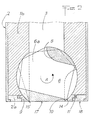
- la figure 2 est une coupe partielle, selon le plan II-II de la figure 1, de l'ensemble monté.
- Figure 1 is an overview of a nozzle or filling horn equipped with the improvement according to the invention;
- Figure 2 is a partial section along the plane II-II of Figure 1, of the mounted assembly.
Le cornet représenté sur ces figures est essentiellement constitué d'un noyau intérieur 1 susceptible d'être logé dans une douille extérieure 2. Montés l'un dans l'autre, le noyau 1 et la douille 2 sont rendus solidaires par des moyens non représentés. Le noyau 1 est constitué par deux demi-coquilles 1a et 1b attelées l'une à l'autre au moyen de vis 1c. Ces demi-coquilles délimitent intérieurement un conduit cylindrique 3 et leur surface extérieure globale est également cylindrique d'un diamètre sensiblement égal au diamètre intérieur de la douille 2. On notera que le cylindre extérieur est de manière non limitative, excentré par rapport au conduit intérieur, la demi-coquille 1a étant pourvue d'éléments de commande du fonctionnement du cornet qui seront décrits ci-après. La douille 2 possède une paroi avant frontale 2a pourvue d'un orifice 4 susceptible d'être placé en alignement avec le conduit 3.The horn shown in these figures essentially consists of an
A l'extrémité avant du conduit 3 on a placé une bille 5 sphérique articulée dans le noyau 1 autour d'un axe diamétral perpendiculaire au plan de joint des deux coquilles, c'est-à-dire perpendiculaire au plan de la figure 2. Cette bille 5 est creusée d'un canal traversant 6 qui peut être placé dans le prolongement du conduit 3 comme représenté sur la figure 1 dans une première position de la bille 5 autour de son articulation ou qui peut être placé sensiblement perpendiculaire à ce conduit comme le montre la figure 2. Ainsi la bille 5 fonctionne comme un obturateur du conduit 3.At the front end of the
La manœuvre de la bille 5 est assurée par deux tiges 7 et 8 montés librement dans des fentes 7a ménagées longitudinalement dans la demi-coquille 1a et articulés à la bille 5 au niveau de méplats 5a qu'elle possède perpendiculairement à son axe de pivotement. L'extrémité libre des tiges 7 et 8 est susceptible d'être attelée à un organe d'entraînement non représenté.The operation of the
Sur la face frontale du noyau 1 on voit une pièce annulaire 9 qui possède un évidement central 10 sphérique débouchant de même rayon que celui de la bille 5. Ainsi, cette pièce annulaire est centrée sur la bille 5 et y est maintenue en appui par la paroi frontale 2a de la douille 2 quand le noyau 1 y est logé. Cette pièce est donc libre en rotation autour d'un axe correspondant à celui du conduit 3 et est extérieurement pourvue d'une denture 11.On the front face of the
Dans un évidement longitudinal ménagé dans la demi-coquille 1a un arbre 12 est susceptible de tourner. Il est équipé à ses extrémités de pignons 12a et 12b, le pignon 12a engrenant avec la denture 11 susdite, le pignon 12b coopérant avec un organe d'entraînement en rotation non représenté. On remarquera que le maintien en position de l'axe 12 est assuré à l'une de ses extrémités par un palier 13 ménagé dans la paroi 2a de la douille 2. Un autre palier est réalisé vers le pignon 12b dans l'évidement longitudinal de la demi-coquille 1a.In a longitudinal recess in the half-shell 1a a
En ce qui concerne la bille 5 on notera que l'intersection 14 du canal 6 constitue une arête dont une partie coopère avec les bords de l'évidement sphérique de la pièce 9 constitués par l'intersection 15 de cet évidement avec la face extérieure de la pièce 9. Cette intersection est affûtée en lame tranchante et la coopération des deux arêtes 14 et 15 constitue un organe de sectionnement du produit s'écoulant par l'extrémité du cornet lorsque la bille passe de sa position en traits mixtes à sa position en traits pleins sur la figure 2 dans le sens de la flèche A. La coupe est réalisée de manière nette car l'arête 15 est en mouvement, la pièce 9 étant entraînée en rotation par l'arbre 12.As regards the
Par ailleurs, on remarquera que la bille 5 possède un méplat extérieur 17 qui, lorsque le conduit 3 est fermé, est contenu dans le plan de la face 18 de la paroi 2a de la douille 2. Cette disposition confère au cornet une surface frontale sans saillie qui laisse donc une surface de produit très lisse. En outre, cette absence de saillie permet de procéder à un raclage de l'extrémité du cornet par les bords supérieurs du récipient.Furthermore, it will be noted that the
Enfin, il faut signaler que le conduit 6 possède une estrémité 6a opposée à celle de sortie du produit très évasée qui permet d'éviter un cisaillement du produit au niveau de cette extrémité entre le noyau 1 et la bille 5, cisaillement qui pourrait notamment détériorer les morceaux de matière pouvant être écrasés sans être coupés totalement.Finally, it should be noted that the
La description donnée ci-dessus a été faite en relation avec un cornet de forme extérieure cylindrique. Bien évidemment, et c'est là l'un des grands avantages de l'invention en ce qu'elle comporte un couteau tournant indépendamment de la douille extérieure fixe, la forme extérieure du cornet peut être quelconque et ainsi correspondre à toutes les sections de récipients que l'on peut rencontrer sur le marché. D'une manière générale, l'invention n'est pas limitée à la description qui vient d'en être donnée mais couvre au contraire toutes les variantes qui pourraient lui être apportées sans sortir de son cadre ni de son esprit.The description given above was made in relation to a horn of cylindrical external shape. Obviously, and this is one of the great advantages of the invention in that it comprises a knife rotating independently of the fixed external sleeve, the external shape of the horn can be arbitrary and thus correspond to all the sections of containers that can be found on the market. In general, the invention is not limited to the description which has just been given, but on the contrary covers all the variants which could be made to it without departing from its scope or its spirit.
L'invention trouve une application intéressante dans le domaine de la conserverie alimentaireThe invention finds an interesting application in the field of food canning
Claims (4)
Applications Claiming Priority (2)
| Application Number | Priority Date | Filing Date | Title |
|---|---|---|---|
| FR8008534A FR2480706A1 (en) | 1980-04-16 | 1980-04-16 | IMPROVEMENT TO APPLIANCES FOR FILLING CONTAINERS |
| FR8008534 | 1980-04-16 |
Publications (2)
| Publication Number | Publication Date |
|---|---|
| EP0038261A1 EP0038261A1 (en) | 1981-10-21 |
| EP0038261B1 true EP0038261B1 (en) | 1985-11-21 |
Family
ID=9240952
Family Applications (1)
| Application Number | Title | Priority Date | Filing Date |
|---|---|---|---|
| EP81400578A Expired EP0038261B1 (en) | 1980-04-16 | 1981-04-10 | Apparatuses for filling containers |
Country Status (4)
| Country | Link |
|---|---|
| US (1) | US4401238A (en) |
| EP (1) | EP0038261B1 (en) |
| DE (1) | DE3172960D1 (en) |
| FR (1) | FR2480706A1 (en) |
Families Citing this family (3)
| Publication number | Priority date | Publication date | Assignee | Title |
|---|---|---|---|---|
| US5102599A (en) * | 1987-11-17 | 1992-04-07 | General Electric Company | Method of and apparatus for cutting tails of viscous material |
| US5524863A (en) * | 1994-06-08 | 1996-06-11 | Daniel Industries, Inc. | Quarter turn rotatable flow control valve |
| US6219996B1 (en) * | 1999-05-17 | 2001-04-24 | Sweetheart Cup Company, Inc. | Systems for filling non-round containers, especially frozen dessert containers |
Family Cites Families (6)
| Publication number | Priority date | Publication date | Assignee | Title |
|---|---|---|---|---|
| US2302404A (en) * | 1941-04-17 | 1942-11-17 | Gen Electric | Valve |
| US3157190A (en) * | 1960-05-26 | 1964-11-17 | Cameron Iron Works Inc | Ball valve |
| US3228412A (en) * | 1962-07-16 | 1966-01-11 | Bartelt Engineering Co Inc | Dispensing valve having particular cleaning means |
| FR1434460A (en) * | 1965-03-18 | 1966-04-08 | Schmitt Fkf Werke | Apparatus for boxing material into pieces |
| DE1561973A1 (en) * | 1967-01-28 | 1970-04-02 | Benz & Hilgers Gmbh | Abfuellmundstueck for viscous or soft plastic food and beverages |
| FR2086969A5 (en) * | 1970-04-15 | 1971-12-31 | Genvrain Sa |
-
1980
- 1980-04-16 FR FR8008534A patent/FR2480706A1/en active Granted
-
1981
- 1981-04-10 DE DE8181400578T patent/DE3172960D1/en not_active Expired
- 1981-04-10 EP EP81400578A patent/EP0038261B1/en not_active Expired
- 1981-04-14 US US06/254,047 patent/US4401238A/en not_active Expired - Lifetime
Also Published As
| Publication number | Publication date |
|---|---|
| FR2480706A1 (en) | 1981-10-23 |
| DE3172960D1 (en) | 1986-01-02 |
| EP0038261A1 (en) | 1981-10-21 |
| FR2480706B1 (en) | 1984-06-08 |
| US4401238A (en) | 1983-08-30 |
Similar Documents
| Publication | Publication Date | Title |
|---|---|---|
| EP0538094B1 (en) | Metal container which can be partially opened by tearing along a line of weakness | |
| EP1066787A1 (en) | Paperweb roll dispenser with centre feeding out | |
| FR2775679A1 (en) | CAN OPENER | |
| FR2543024A1 (en) | DISPENSING DEVICE IN THE FORM OF A SUCTION PISTOL | |
| BE1001250A5 (en) | CHUCK FOR MACHINE dicked MEAT. | |
| FR2859367A1 (en) | DEVICE FOR CONTROLLING THE OUTPUT OF A CUTTING BLADE OF A DRUM IN A TOWING EQUIPMENT DISPENSING DEVICE | |
| EP0038261B1 (en) | Apparatuses for filling containers | |
| BE1003871A3 (en) | Mechanism combined pumps, block assembly and mechanism for machine pushing meat using the envelope. | |
| EP0904697A1 (en) | Portioning device on sausage stuffing machine | |
| CH636703A5 (en) | DOSING MACHINE FOR PRODUCTS OF LIQUID CONSISTENCY WITH PASTE. | |
| EP0151377A1 (en) | Device for filling cigarette paper tubes | |
| WO1991015409A1 (en) | Device for automatic delivery of any product or object | |
| FR2617679A1 (en) | PETREIN FOR PASTA MATERIAL, ESPECIALLY FOR BREAD | |
| FR2553306A1 (en) | PAINT APPARATUS WITH A ROLLER PROVIDED WITH AN AUTOMATIC FEEDING PISTON | |
| EP2260984A1 (en) | Method and device for slicing bread | |
| FR2620959A1 (en) | BATI WITH TABLE FOR CHAINSAW OR HAND GRINDER | |
| EP0586272B1 (en) | Dispenser for rolled-up paper | |
| FR2591212A1 (en) | CAPPER-FORMING DEVICE, IN PARTICULAR FOR A SMALLER WINE BOTTLE, SUCH AS CHAMPAGNE | |
| FR2562444A1 (en) | Device for manual dispensing of a liquid product | |
| FR2643799A1 (en) | PRODUCT DISPENSING DEVICE, PARTICULARLY COSMETIC, PORTABLE | |
| EP1345514A1 (en) | Measuring and dispensing device | |
| FR2708437A1 (en) | Case for a stick of cosmetic, pharmaceutical or similar pasty product | |
| EP1227057B1 (en) | Bottle seal cutter | |
| EP0791548A2 (en) | Device for automating opening and closing of a hinged bearing | |
| FR2684568A1 (en) | Oscillating sprinkler device |
Legal Events
| Date | Code | Title | Description |
|---|---|---|---|
| PUAI | Public reference made under article 153(3) epc to a published international application that has entered the european phase |
Free format text: ORIGINAL CODE: 0009012 |
|
| AK | Designated contracting states |
Designated state(s): DE GB IT NL |
|
| 17P | Request for examination filed |
Effective date: 19811024 |
|
| ITF | It: translation for a ep patent filed |
Owner name: JACOBACCI & PERANI S.P.A. |
|
| GRAA | (expected) grant |
Free format text: ORIGINAL CODE: 0009210 |
|
| AK | Designated contracting states |
Designated state(s): DE GB IT NL |
|
| REF | Corresponds to: |
Ref document number: 3172960 Country of ref document: DE Date of ref document: 19860102 |
|
| PLBE | No opposition filed within time limit |
Free format text: ORIGINAL CODE: 0009261 |
|
| STAA | Information on the status of an ep patent application or granted ep patent |
Free format text: STATUS: NO OPPOSITION FILED WITHIN TIME LIMIT |
|
| 26N | No opposition filed | ||
| PGFP | Annual fee paid to national office [announced via postgrant information from national office to epo] |
Ref country code: NL Payment date: 19870430 Year of fee payment: 7 |
|
| PG25 | Lapsed in a contracting state [announced via postgrant information from national office to epo] |
Ref country code: GB Effective date: 19890410 |
|
| PG25 | Lapsed in a contracting state [announced via postgrant information from national office to epo] |
Ref country code: NL Effective date: 19891101 |
|
| GBPC | Gb: european patent ceased through non-payment of renewal fee | ||
| NLV4 | Nl: lapsed or anulled due to non-payment of the annual fee | ||
| PGFP | Annual fee paid to national office [announced via postgrant information from national office to epo] |
Ref country code: DE Payment date: 20000408 Year of fee payment: 20 |