EP0038169A2 - Vorrichtung zum Stapeln von Bogen - Google Patents
Vorrichtung zum Stapeln von Bogen Download PDFInfo
- Publication number
- EP0038169A2 EP0038169A2 EP81301525A EP81301525A EP0038169A2 EP 0038169 A2 EP0038169 A2 EP 0038169A2 EP 81301525 A EP81301525 A EP 81301525A EP 81301525 A EP81301525 A EP 81301525A EP 0038169 A2 EP0038169 A2 EP 0038169A2
- Authority
- EP
- European Patent Office
- Prior art keywords
- stack
- moving
- microprocessor
- operable
- divider
- Prior art date
- Legal status (The legal status is an assumption and is not a legal conclusion. Google has not performed a legal analysis and makes no representation as to the accuracy of the status listed.)
- Granted
Links
Images


Classifications
-
- B—PERFORMING OPERATIONS; TRANSPORTING
- B65—CONVEYING; PACKING; STORING; HANDLING THIN OR FILAMENTARY MATERIAL
- B65H—HANDLING THIN OR FILAMENTARY MATERIAL, e.g. SHEETS, WEBS, CABLES
- B65H33/00—Forming counted batches in delivery pile or stream of articles
- B65H33/06—Forming counted batches in delivery pile or stream of articles by displacing articles to define batches
- B65H33/08—Displacing whole batches, e.g. forming stepped piles
-
- B—PERFORMING OPERATIONS; TRANSPORTING
- B65—CONVEYING; PACKING; STORING; HANDLING THIN OR FILAMENTARY MATERIAL
- B65H—HANDLING THIN OR FILAMENTARY MATERIAL, e.g. SHEETS, WEBS, CABLES
- B65H2301/00—Handling processes for sheets or webs
- B65H2301/40—Type of handling process
- B65H2301/42—Piling, depiling, handling piles
- B65H2301/421—Forming a pile
- B65H2301/4219—Forming a pile forming a pile in which articles are offset from each other, e.g. forming stepped pile
- B65H2301/42194—Forming a pile forming a pile in which articles are offset from each other, e.g. forming stepped pile forming a pile in which articles are offset from each other in the delivery direction
Definitions
- This invention concerns improvements in or relating to apparatus for forming a stack from a succession of sheets of, for example, paper.
- sheets it is usual for sheets to be formed into large stacks either by a delivery unit which is raised in unison with the growing stack or more usually the sheets are collected on a platform or table which descends at the growing rate of the stack.
- These stacks are often required to be separated into smaller batches or portions (e.g. a ream of 500 sheets) for feeding to machines for carrying out further operations such as wrapping the reams in an outer wrapper.
- apparatus for forming a stack from a succession of sheets including support means on which said stack is formed, means for feeding said sheets in succession onto said support means, stop means for arresting lengthwise motion of said sheets whilst being fed onto said support means, characterised by gripping means for gripping a portion of said stack, and first means for moving said gripping means to offset the gripped portion relative to the next adjacent portion of the stack.
- the apparatus may include second means for moving said support means downwards as the stack grows, to keep the top of the stack at a constant level.
- the gripping means may comprise first and second gripper plate means, third moving means for moving said gripper plate means vertically, said first and third moving means being operable to move each gripper plate means independently along similar closed paths in a vertical plane so that each gripper plate means moves in succession into said stack, downwards with said stack, out of said stack and upwards, the motions of the gripper plate means being out of phase so that in alternation each gripper plate means changes its vertical position relative to the other gripper plate means, each gripper plate means alternately becoming the upper and lower one.
- a required number of portions may be removed from beneath the rest of the stack by moving the support means horizontally and supporting the rest of the stack on auxiliary support means.
- a microprocessor may be used for controlling the operation of the moving means in a predetermined timed sequence.
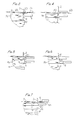
- a stream of overlapped sheets is fed to the right by a pair of cooperating rollers 1 and on leaving the nip of these rollers each sheet travels further to the right above a stack S, in the course of formation, until it strikes a stop means in the form of a backboard 2, whereupon the sheet falls on top of the stack.
- the left hand edge of the stack is kept in alignment by known vibrating plates 3.
- the stack is formed on a support platform 4 comprising a table 85 (to be described in more detail later) which extends across the width of the machine and is carried on a pair of cross members 86 supported at each end on beams 87, one such beam being- provided on each side of the machine.
- the beams 87 are supported on further cross members 88 which support plates 89, 89a on each side of the machine.
- the plates 89, 89a are provided respectively with wheels 90, 91 which run on rails 92 fixed to carrier beams 93.
- the latter each have a chain 60 attached to each end thereof, which thus support the platform 4.
- the platform 4 is raised and lowered by the chains 60 ( Figure 2B), which are driven in known manner by a motor 61, the table being constrained to move in a vertical path by guides 60a.
- the platform is lowered a short distance at a time, under the control of a photoelectric stack height sensor 62 ( Figure 1), of any suitable type, so that the top of the stack S is maintained at optimum spacing below the path of sheets from rollers 1 to the backboard 2.
- Vertical movement of the platform 4 is detected by a positional transducer 94 ( Figure 2B), of any convenient type, which is fixed on the rail 93.
- a pinion 95 engaging a rack 96 fixed to one of the guides 60a, rotates as the platform 4 moves, and the transducer 94 emits pulses, as the pinion rotates, indicative of the vertical position of the platform, which pulses are fed to a central microprocessor control unit 97 ( Figure 14B) referred to later; the motor 61 also being connected thereto.
- Tapes 63 which pass round pulleys 64, 64a, extend across the top of the stack, in known manner, to ensure that the sheets are fed correctly to the top of the stack.
- the pulley 64 is mounted on a toothed quadrant 65, pivoted at 66, and meshing with a gear 67. The latter is rotated to move the quadrant about its pivot, and thus move the pulley 64 up or down depending on the required position of the tapes 63.
- stack S Although only one stack S is shown, it should be noted that a number of stacks may be formed simultaneously across the width of the machine, the sides of adjacent stacks being kept in alignment by vibrating plates 68 of known type.
- a photoelectric detector 81 which, for each sheet, emits a pulse which is fed to a counter 82 and moves the count up by one.
- the counter emits pulses, indicative of the count, which are fed to the unit 97. It is common, in machines of this type, to feed the sheets, as "spurs" (i.e. a number of superimposed sheets). In this case the counter 82 would be arranged to move up by the number of sheets in the "spur" each time a pulse is emitted from detector 81.
- the portion Pl is separated, at the right hand end thereof, from the portion P below it by a number of gripper plates 5 spaced across the stack, only one being visible.
- Each gripper 5 is carried by an arm 6 which is moved, at predetermined times, backwards and forwards horizontally by means of a lever 7 fixed on a rotatable shaft 8.
- the lever 7 carries a roller which runs in a vertical channel 9 formed in an extension 10 of the arm 6.
- An arm 7a, also fixed on the shaft 8, carries a cam follower 69 which engages with a cam 70 fixed to a shaft 71 driven from the output side of a single-revolution clutch 72 through a reduction gearbox 72a, so that the shaft 71 rotates through 90 o for each revolution of the output side of the clutch 72.
- the input side of the clutch is driven continuously by a motor 73.
- the clutch 72 is operated, under the control of unit 97, to drive the end of shaft 71 carrying the cam 70 at certain times, to move the gripper plate 5 into and out of the stack S, as will be described later.
- the arm 6 is constrained to move in a horizontal plane by rollers 11 mounted on a vertical support 12 which itself'is movable in a vertical plane on rollers 13 which run on rails 14 carried on a fixed support 15.
- the support 12, and thus also the gripper 5, are raised by a lever 16, which is fixed, at one end, on a rotatable shaft 17.
- lever 16 contacts the bottom surface of a block 18 fixed to the support 12.
- a lever 16a also fixed to shaft 17, is attached to the piston of a pneumatic cylinder 74, air being fed to the cylinder at appropriate times via an electromagnetic valve 75, which is connected to, and operated under the control of unit 97.
- the support 12 lowers by reason of its own weight as will be described later.
- each gripper plate 5 is a second gripper plate 20 which is movable horizontally and vertically, independently of the gripper plate 5, in a similar manner to the plate 5.
- Each gripper 20 is moved horizontally by a lever 21, vertical channel 22 and arm 23 which correspond respectively to the lever 7, vertical channel 9 and arm 6, the lever 21 being fixed to a rotatable shaft 8a.
- a lever 91a also fixed to shaft 8a, carries a cam follower 78 Wich engage, with a cam 79, similar to the cam 70, and stepwise in unison but out of phase.
- the upward movement of plate 20 is obtained from a lever 24 which, at one end thereof, contacts a block 25 fixed to a support (not shown) similar to support 12, the other end being fixed to a rotatable shaft 17a.
- the plate 20 moving downwards by reason of its own weight.
- a lever 24a, also fixed to shaft 17a, is attached to the piston of a pneumatic cylinder 76.
- the lever 24, as with the lever 16, is operated at appropriate times by the pneumatic cylinder 76, air being fed thereto via a electromagnetic valve 77, which is also connected to, and operated under the control of, unit 97.
- the support 12 also carries a pair of further blocks 26, 27 and, similarly, the support plate associated with the gripper 20 also carries a pair of further blocks 28, 29.
- the grippers 5, 20 are chamfered at their left hand edges and are so constructed that air under pressure may be fed out through apertures in their left hand edges to provide a layer of air between the surfaces of the sheets between which they are moved, as will be described later.
- the free ends of the levers 31, 32 are arranged to contact respectively the blocks 26 and 29 or 28 and 27, depending on the relative positions of the blocks, 18, 25, so as to urge the grippers 5, 20 towards each other, as will be described later.
- the control unit 97 is a microprocessor which, in known manner, controls the motors 61, 73 clutch 72 and valves 75, 77 and 80 according to a pre-set programme so that the various operations take place in the correct sequence and at the correct time, as will now be described.
- a number of pairs of gripper plates 5, 20 are provided, spaced apart across the width of each stack being formed. Each pair is operated by separate levers, corresponding to levers 7, 21, 16, 24 which are fixed to respective shafts 8, 8a, 17, 17a. However, a separate cylinder, corresponding to cylinder 30 is provided for each pair of grippers 5, 20.
- the gripper plate 20 When the count in counter 82 reaches the required number of sheets to form the portion Pl, the gripper plate 20 is lowered on to the top of the portion Pl, by the valve 77 being operated so that the cylinder 76 moves the lever 24 clockwise about its pivot. When the gripper 20 contacts the top of portion Pl the lever 24 continues its clockwise movement and moves away from the block 25. Also, at this time, the lever 16 is away from the block 18.
- the grippers 5, 20 are now supported only by the stack and will thus move downwards, under their own weight, in unison with the stack.
- valve 80 is now operated so that cylinder 30 moves the levers 31, 32 about their pivots so as to apply pressure to the blocks 26, 29 respectively which urge the support plate 12 upwards, and the support plate associated with the divider plate 20, downwards, thus urging the grippers 5 and 20 together so that they firmly grip the portion Pl between them.
- the clutch 72 is energised to rotate the cams 70, 79 so that the levers 7, 21 are operated to move the grippers 5 and 20, and therefore also the portion Pl, to the right a predetermined distance, thus producing a step in the stack (Figure 5).
- the clutch 72 is then de-energised. At the same time air is blown from the front of both grippers 5 and 20 to lubricate the sheets above and below the portion Pl to ensure easy movement.
- the valve 80 is now operated so that cylinder 30 moves the levers 31, 32 to release the grip of the grippers 5, 20.
- the clutch 72 is energised so as to rotate the cams 70, 79 to move the gripper 20 to the left so that it again extends fully into the stack ( Figure 6).
- the gripper 5 is now fully withdrawn from the stack ( Figure 6) by operation of the lever 7 by cam 70, and the clutch 72 is de-energised.
- the gripper 5 is raised to a position above the level of the top of the stack S ( Figure 7), by operation of the lever 16, which is caused to move anticlockwise about its pivot by cylinder 74 on operation of the valve 75.
- the clutch 72 is then again energised to cause operation of the lever 7 so that the gripper 5 is moved to the left to the position occupied by the gripper 20 in Figure 1.
- next portion P in the stack S is the same as just described in relation to the portion Pl with the exception that the positions of the grippers 5 and 20 are reversed and the valve 80 is not operated to cause the cylinders 30 to urge them together and they thus do not grip the portion between them. Thus this portion is not offset to the right as was the portion Pl.
- the gripper plates need not always grip and offset every alternate portion. A number of successive alternate portions may be offset or not, depending on the arrangement required in the stack, the operations required to produce the stack being controlled from a suitable programme in the unit 97.
- a divider 40 formed from a thin hollow member having an angled front portion 40a ( Figure 2A), and provided with apertures (not shown) through which pressure air is fed to form a layer of air on its surfaces.
- the divider 40 comprises a number of hollow members spaced apart across the machine, only one being visible. It is supported on an auxiliary support in the form of a movable support table 41, the divider 40 and table 41 being movable both horizontally and vertically as will be described later. A layer 98 of low friction material is provided between them to allow relative lengthwise movement therebetween.
- the table 41 which also consists of a number of spaced members, is supported, at each side of the machine by a bean 99. The latter ar2 supported on cross members 100, 100a to which plates 101, 101a are respectively fixed, on each side of the machine, the plates being provided respectively with wheels 102, 103 which run on rails 104 fixed to long carrier beams 105.
- each of the beams 105 Fixed to each of the beams 105 is a toothed rack 108 which are engaged by gear wheels 109 carried on a cross shaft 109a journalled in the plates 101.
- Carried on the cross members 100 is a motor 110 drivingly connected to the shaft 109a by a chain 111.
- the motor 110 is controlled by the unit 97, so that at the appropriate times the motor is operated to rotate the gear 109 and thus move the table 41 towards and away from the stack, as will be described. Movement of the table is detected by a positional transducer 112 which is fixed to the plate 101 and emits pulses, indicative of the horizontal position of the table 41, which are fed to the unit 97.
- the divider 40 is fixed at each side of the machine to a plate 113, the latter being joined also by cross members 114.
- Each plate 113 is provided with wheels 115 which run on the rails 104.
- the divider 40 is moved, at appropriate times, into and out of the stack by a gear 116 which engages the rack 108 and is driven by a chain 117 from a motor 118.
- the latter is controlled from the unit 97 and the horizontal position of the divider is detected by a positional transducer 119, similar to the transducer 112, fixed to the plate 113.
- the carrier beams 105 are each supported, at the left hand end, by a connecting rod 120, and about halfway along their lengths by a support rod 121.
- the upper end of rod 121 is loosely connected, at 122 to the beam 105 and the lower end is pivotally connected to one arm of a bell-crank lever 123, mounted on a fixed pivot 124.
- the other arm of the lever 123 is fixed at its free end to a chain 125 which engages a sprocket 126 fixed on the shaft of a motor 127, controlled by unit 97.
- the beam 105 rests on top of the rod 121, the lower end of which contacts a roller 128 carried on one arm of a further bell-crank lever 129 mounted on a fixed pivot 130.
- the rod 121 is constrained to move vertically by guides 131.
- the other arm of lever 129 is connected to one end of a bar 132, the other end of which is connected to the other arm of the lever 123.
- the left hand end of the beam 105 carries a roller 133 which runs in a fixed track 134, to guide the beam in a vertical path.
- the arrangement is such that when the motor 127 is operated, the levers 123, 129 rotate on their respective pivots to move the divider 40 and table 41 vertically.
- This movement is detected by a positional transducer 135 mounted on a fixed part of the machine, and having a pinion 136 which engages a rack 137 on the rod 121. Movement of the latter rotates the pinion and the transducer emits pulses, indicative of the vertical position of the divider 40 and table 41, which are fed to the unit 97.
- each of the beams 93 Fixed to each of the beams 93 ( Figure 2B) is a rack 138 which are engaged by gear wheels 139 rotatably carried on a cross-shaft 140 journalled in the plates 89.
- the gears 139 are driven from a motor 141 by a chain 142 so as to move the platform 4 horizontally, as will be described later, such movement being detected by a positional transducer 143 which is operated to send pulses, indicative of the horizontal position of the platform 4, to the unit 97.
- the table 85 comprises a number of slats 144 ( Figures 8, 9) spaced apart across the width of the table, each slat being provided with a row of apertures 145 in its upper surface.
- the apertures in each slat communicate with a hollow chamber 146, one such chamber being provided for each slat. Air under pressure is supplied at appropriate times, from a pump (not shown), to the chambers 146 and out through the apertures 145.
- An endless chain conveyor 147 is provided in each of the spaces between adjacent slats 144.
- Each chain 147 carries a single pusher 148 positioned so that all the pushers are in alignment across the table 85.
- Each conveyor 147 passes over sprockets 149, 150, 151 and 152, all the sprockets 151 being mounted on a common shaft 153. The latter is driven by a chain 155 from a motor 154, fixed on one of the cross members 88.
- the pushers 148 Whilst a stack is being formed on the table 85 the pushers 148 are stationary in the position shown in Figure 8.
- the motor 154 is operated at certain times, by the unit 97, to drive the conveyors 147 in a clockwise direction and the pushers 148 push the completed stack off the table 85, the position of the pushers 148 being indicated to the unit 97 by pulses emitted by a positional transducer 156 mounted on the shaft 153.
- blocking means in the form of a pad 157 ( Figure 1) is provided.
- the pad is fixed to a cross member 158 having a plate 159 attached to each end thereof, only one plate being visible, and being slideable between horizontal guide rails 160 carried on a side plate 160a.
- the plates 159 and thus also the pad 157, are moved by an arm 161 connected to one arm of a bell-crank lever 162, pivoted at 163, the other arm of which is connected to the piston rod of a pneumatic cylinder 165.
- the latter is supplied with air via a valve 166 under the control of the unit 97.
- the pad 157 Whilst the pad 157 is in contact with the stack it moved downwards in unison therewith. For this movement the plate 160a runs between wheels 167, 168 carried on a fixed part of the machine, and the movement is derived from the carrier beam 105, on which runs a wheel 169 mounted on an extension of the plate 160a. Thus-the pad 157 is moved upwards by the beam 105 and downwards under the weight of the plate 160a and the attached parts, as the beam 105 so moves.
- motor 141 When divider 40 reaches the position shown in Figure 11, motor 141 is operated to move the table 85, and thus also the completed stack, horizontally to the right. At the same time motor 110 is operated to move the support table 41 also to the right so that the portions P above the stack being removed are supported by table 41 by the time this movement is completed ( Figure 11).
- the pad 157 prevents the portion P next above divider 40 from also moving to the right during this movement.
- valve 166 When the various parts reach the positions shown in Figure 12, valve 166 is operated so that cylinder 165 withdraws pad 157 to the right, pressure air is supplied to chambers 146 ( Figure 8) and out through apertures 145 to provide a layer of air on the upper surface of table 85 and the motor 61 is stopped. Also, motor 154 ( Figure 2B) is operated to drive the conveyor 147 in a clockwise direction so that pushers 148 push the completed stack to the right, off the table 85, after which the motor 154 is stopped and the air supply to chambers 146 is turned off. The stack then has further operations carried out on it as will be described later.
- the motor 141 is now operated to move the empty platform 4 to the left to a position to the right of the position it is shown occupying in Figure 10. Whilst this movement is taking place the motor 154 is operated to drive the conveyors 147 in an anti-clockwise direction to move the pushers 148 back to their starting position shown in Figure 8.
- Motor 61 is now operated to raise the platform 4 such that the upper surface of table 85 is level with the upper surface of the table 41.
- Motors 141, 110 and 118 are then operated to move divider 40, table 41 and platform 4 together to the left until they occupy the positions shown in Figure 13, at which time the motor 127 is stopped and the stack being formed is again supported by the platform 4.
- motor 61 is operated to move the platform 4 downwards again, under the control of sensor 62.
- Motor 127 is now operated to rotate sprocket 126 anticlockwise to raise plate 40, table 41 and pad 157 back to the positions shown in Figure 1.
- the completed stacks after being removed from the table 4, are fed along a conveyor 170 to a transverse conveyor 171 from which the stacks are fed to a machine 172 of any known type which separates each individual portion from the stacks.
- each row of portions is red respectlvely to machines 175, 176 which enclose each portion in a carton having a lower body half and an upper lid half.
- the filled cartons are then shrink-wrapped at 177 and formed into large batches in a palletising unit 178.
Landscapes
- Pile Receivers (AREA)
- Folding Of Thin Sheet-Like Materials, Special Discharging Devices, And Others (AREA)
- Forming Counted Batches (AREA)
- Basic Packing Technique (AREA)
Priority Applications (1)
| Application Number | Priority Date | Filing Date | Title |
|---|---|---|---|
| AT81301525T ATE15021T1 (de) | 1980-04-10 | 1981-04-08 | Vorrichtung zum stapeln von bogen. |
Applications Claiming Priority (2)
| Application Number | Priority Date | Filing Date | Title |
|---|---|---|---|
| GB8011880 | 1980-04-10 | ||
| GB8011880 | 1980-04-10 |
Publications (3)
| Publication Number | Publication Date |
|---|---|
| EP0038169A2 true EP0038169A2 (de) | 1981-10-21 |
| EP0038169A3 EP0038169A3 (en) | 1982-02-10 |
| EP0038169B1 EP0038169B1 (de) | 1985-08-21 |
Family
ID=10512713
Family Applications (1)
| Application Number | Title | Priority Date | Filing Date |
|---|---|---|---|
| EP81301525A Expired EP0038169B1 (de) | 1980-04-10 | 1981-04-08 | Vorrichtung zum Stapeln von Bogen |
Country Status (5)
| Country | Link |
|---|---|
| US (1) | US4396334A (de) |
| EP (1) | EP0038169B1 (de) |
| JP (1) | JPS578620A (de) |
| AT (1) | ATE15021T1 (de) |
| DE (1) | DE3171884D1 (de) |
Cited By (5)
| Publication number | Priority date | Publication date | Assignee | Title |
|---|---|---|---|---|
| GB2121011A (en) * | 1982-05-25 | 1983-12-14 | Gaylor Knight Limited | Mechanical handling apparatus |
| DE3307821A1 (de) * | 1983-03-05 | 1984-09-13 | Bielomatik Leuze Gmbh + Co, 7442 Neuffen | Vorrichtung zum stapeln von gebundenen blattlagen |
| DE3437348A1 (de) * | 1984-10-11 | 1986-04-24 | NORFIN Graphische Produkte GmbH, 3014 Hannover | Vorrichtung zur markierung der einzelnen auflagen oder druckbogenteilstapel auf dem ablagetisch einer druckmaschine |
| DE3730403A1 (de) * | 1987-09-10 | 1989-03-23 | Hoechst Ag | Vorrichtung zum abstapeln von flaechengut |
| EP0365284A1 (de) * | 1988-10-17 | 1990-04-25 | Xerox Corporation | Vorrichtung zum Auslegen einer Gruppe von Blättern |
Families Citing this family (9)
| Publication number | Priority date | Publication date | Assignee | Title |
|---|---|---|---|---|
| JPS59169438U (ja) * | 1983-04-28 | 1984-11-13 | 友信株式会社 | 無励磁作動式電磁ブレ−キ |
| CA1217212A (en) * | 1983-12-01 | 1987-01-27 | Brian Otter | Paper stacker |
| JPS6158661A (ja) * | 1984-08-29 | 1986-03-25 | 帝人株式会社 | 血液浄化器 |
| DE3616470A1 (de) * | 1985-12-17 | 1987-06-25 | Jagenberg Ag | Verfahren und vorrichtung zum ablegen kontinuierlich zu einer stapelstelle gefoerderter bogen |
| US6022186A (en) * | 1997-09-25 | 2000-02-08 | Roll Systems, Inc. | Method and apparatus for sorting stacks |
| US6293543B1 (en) * | 1999-01-26 | 2001-09-25 | Gradco (Japan) Ltd. | Universal sheet receiver for stackers |
| US7417752B2 (en) * | 2001-07-02 | 2008-08-26 | Pitney Bowes Inc. | Method and system for customized mail piece production utilizing a data center |
| JP4096624B2 (ja) * | 2002-05-23 | 2008-06-04 | コニカミノルタホールディングス株式会社 | 用紙スタッカー |
| US8870066B2 (en) * | 2002-11-25 | 2014-10-28 | Diebold Self-Service Systems Division Of Diebold, Incorporated | Banking apparatus controlled responsive to data bearing records |
Citations (3)
| Publication number | Priority date | Publication date | Assignee | Title |
|---|---|---|---|---|
| GB1042361A (en) * | 1964-01-01 | 1966-09-14 | Paper Converting Machine Co | Improvements in stacking and handling apparatus for flat sheet like objects |
| GB1162454A (en) * | 1967-12-20 | 1969-08-27 | Paper Converting Machine Co | Delivery Apparatus for Web Segments to be Stacked. |
| US3860127A (en) * | 1973-10-15 | 1975-01-14 | Pitney Bowes Inc | Offset stacking mechanism |
Family Cites Families (7)
| Publication number | Priority date | Publication date | Assignee | Title |
|---|---|---|---|---|
| US2950108A (en) * | 1957-05-29 | 1960-08-23 | Golding William Frank | Printing and like machines |
| US3298683A (en) * | 1964-11-25 | 1967-01-17 | William F Stroud | Paper-jogging apparatus |
| DE2328659A1 (de) * | 1973-06-06 | 1975-01-02 | Wupa Maschf Gmbh & Co | Verfahren und vorrichtung zum stapeln von bogenzuschnitten mit im verhaeltnis zur zuschnittflaeche grosser stapelhoehe |
| US4043458A (en) * | 1976-03-02 | 1977-08-23 | Gloucester Engineering Co., Inc. | Stacker |
| US4162649A (en) * | 1977-05-18 | 1979-07-31 | Wiggins Teape Limited | Sheet stack divider |
| DE2835416A1 (de) * | 1978-08-12 | 1980-02-21 | Will E C H Gmbh & Co | Vorrichtung zum uebergeben einer lage aus papier von einer sammelstation an einen abfoerderer |
| JPS5589158A (en) * | 1978-12-26 | 1980-07-05 | Mitsubishi Heavy Ind Ltd | Counting and discharging device for sheet |
-
1981
- 1981-04-07 US US06/251,822 patent/US4396334A/en not_active Expired - Fee Related
- 1981-04-08 AT AT81301525T patent/ATE15021T1/de not_active IP Right Cessation
- 1981-04-08 EP EP81301525A patent/EP0038169B1/de not_active Expired
- 1981-04-08 DE DE8181301525T patent/DE3171884D1/de not_active Expired
- 1981-04-10 JP JP5425881A patent/JPS578620A/ja active Pending
Patent Citations (3)
| Publication number | Priority date | Publication date | Assignee | Title |
|---|---|---|---|---|
| GB1042361A (en) * | 1964-01-01 | 1966-09-14 | Paper Converting Machine Co | Improvements in stacking and handling apparatus for flat sheet like objects |
| GB1162454A (en) * | 1967-12-20 | 1969-08-27 | Paper Converting Machine Co | Delivery Apparatus for Web Segments to be Stacked. |
| US3860127A (en) * | 1973-10-15 | 1975-01-14 | Pitney Bowes Inc | Offset stacking mechanism |
Non-Patent Citations (1)
| Title |
|---|
| Research Disclosure, No. 167, March 1978, Industrial Opportunities Ltd. Homewell, Havant, Hampshire, G.B. 16738 "Disclosed Anonymously", pages 61-67 * |
Cited By (7)
| Publication number | Priority date | Publication date | Assignee | Title |
|---|---|---|---|---|
| GB2121011A (en) * | 1982-05-25 | 1983-12-14 | Gaylor Knight Limited | Mechanical handling apparatus |
| DE3307821A1 (de) * | 1983-03-05 | 1984-09-13 | Bielomatik Leuze Gmbh + Co, 7442 Neuffen | Vorrichtung zum stapeln von gebundenen blattlagen |
| US4623291A (en) * | 1983-03-05 | 1986-11-18 | Bielomatik Leuze Gmbh | Piling device for bound sets of sheets |
| DE3437348A1 (de) * | 1984-10-11 | 1986-04-24 | NORFIN Graphische Produkte GmbH, 3014 Hannover | Vorrichtung zur markierung der einzelnen auflagen oder druckbogenteilstapel auf dem ablagetisch einer druckmaschine |
| US4730822A (en) * | 1984-10-11 | 1988-03-15 | Neue Rotaprint Gmbh | Apparatus for marking individual runs or portions of a stack of printed sheets |
| DE3730403A1 (de) * | 1987-09-10 | 1989-03-23 | Hoechst Ag | Vorrichtung zum abstapeln von flaechengut |
| EP0365284A1 (de) * | 1988-10-17 | 1990-04-25 | Xerox Corporation | Vorrichtung zum Auslegen einer Gruppe von Blättern |
Also Published As
| Publication number | Publication date |
|---|---|
| DE3171884D1 (en) | 1985-09-26 |
| EP0038169B1 (de) | 1985-08-21 |
| EP0038169A3 (en) | 1982-02-10 |
| ATE15021T1 (de) | 1985-09-15 |
| US4396334A (en) | 1983-08-02 |
| JPS578620A (en) | 1982-01-16 |
Similar Documents
| Publication | Publication Date | Title |
|---|---|---|
| US4396334A (en) | Sheet stacking apparatus | |
| US4478403A (en) | Sheet stacking apparatus | |
| US4359218A (en) | Continuous sheet collection and discharge system | |
| US4349189A (en) | Module for picking, transportation and depositing of sheeted or folded material | |
| US6164045A (en) | Device for packaging groups of (Individual) packages | |
| US4932190A (en) | Method of and apparatus for assembling and wrapping arrays of cigarette packets and the like | |
| US3966186A (en) | Method and apparatus for feeding inserts selectively | |
| CA1138485A (en) | Device for piling-up flat workpieces, especially blanks for folding boxes | |
| US3338370A (en) | Apparatus for grouping articles into piles | |
| US20130226332A1 (en) | Stacker, stacking system or assembly and method for stacking | |
| KR100350716B1 (ko) | 지폐 다발로부터 지폐 꾸러미를 형성하는 장치 | |
| EP0547027A1 (de) | Vorrichtung zum Einwickeln von Papierbogen-Stapeln | |
| WO1997027108A1 (en) | Method and apparatus for taking over and piling articles supplied in a plurality of rows and for conveying obtained piles of articles to a packaging line | |
| US4570418A (en) | Device for the automatic boxing of bags or sachets into containers | |
| GB2059380A (en) | Introducing stacks of sheets into prefabricated cartons or the like | |
| EP0203397B1 (de) | Verfahren und Vorrichtung zum Einbringen von umhüllten Einheiten von Papierstapeln in Pappschachteln | |
| US4181213A (en) | Apparatus for forming stacks of flat items | |
| US4350330A (en) | Bag unit feeder | |
| US6973766B2 (en) | Device for packing flat articles in transport containers, particularly folded-flat folding boxes in casing cartons | |
| US2793032A (en) | Sheet collating machine | |
| US2971415A (en) | Apparatus for feeding, cutting and stacking flat stock | |
| US1774113A (en) | Sheet-feeding machine | |
| CA1244496A (en) | Bag stacking and indexing conveyor | |
| US3519144A (en) | Stacking system for paperboard blanks | |
| US20030233816A1 (en) | Device for packing flat articles in transport containers, particularly folded-flat folding boxes in casing cartons |
Legal Events
| Date | Code | Title | Description |
|---|---|---|---|
| PUAI | Public reference made under article 153(3) epc to a published international application that has entered the european phase |
Free format text: ORIGINAL CODE: 0009012 |
|
| AK | Designated contracting states |
Designated state(s): AT DE FR GB NL |
|
| PUAL | Search report despatched |
Free format text: ORIGINAL CODE: 0009013 |
|
| AK | Designated contracting states |
Designated state(s): AT DE FR GB NL |
|
| RAP1 | Party data changed (applicant data changed or rights of an application transferred) |
Owner name: THE LANGSTON MACHINE COMPANY LIMITED |
|
| 17P | Request for examination filed |
Effective date: 19821006 |
|
| RAP1 | Party data changed (applicant data changed or rights of an application transferred) |
Owner name: JAGENBERG AG |
|
| GRAA | (expected) grant |
Free format text: ORIGINAL CODE: 0009210 |
|
| RAP1 | Party data changed (applicant data changed or rights of an application transferred) |
Owner name: JAGENBERG AG |
|
| AK | Designated contracting states |
Designated state(s): AT DE FR GB NL |
|
| PG25 | Lapsed in a contracting state [announced via postgrant information from national office to epo] |
Ref country code: AT Effective date: 19850821 |
|
| REF | Corresponds to: |
Ref document number: 15021 Country of ref document: AT Date of ref document: 19850915 Kind code of ref document: T |
|
| REF | Corresponds to: |
Ref document number: 3171884 Country of ref document: DE Date of ref document: 19850926 |
|
| ET | Fr: translation filed | ||
| PLBE | No opposition filed within time limit |
Free format text: ORIGINAL CODE: 0009261 |
|
| STAA | Information on the status of an ep patent application or granted ep patent |
Free format text: STATUS: NO OPPOSITION FILED WITHIN TIME LIMIT |
|
| 26N | No opposition filed | ||
| PGFP | Annual fee paid to national office [announced via postgrant information from national office to epo] |
Ref country code: AT Payment date: 19870324 Year of fee payment: 7 |
|
| PGFP | Annual fee paid to national office [announced via postgrant information from national office to epo] |
Ref country code: NL Payment date: 19870430 Year of fee payment: 7 |
|
| PG25 | Lapsed in a contracting state [announced via postgrant information from national office to epo] |
Ref country code: NL Effective date: 19881101 |
|
| PG25 | Lapsed in a contracting state [announced via postgrant information from national office to epo] |
Ref country code: GB Effective date: 19881118 |
|
| NLV4 | Nl: lapsed or anulled due to non-payment of the annual fee | ||
| GBPC | Gb: european patent ceased through non-payment of renewal fee | ||
| PG25 | Lapsed in a contracting state [announced via postgrant information from national office to epo] |
Ref country code: FR Free format text: LAPSE BECAUSE OF NON-PAYMENT OF DUE FEES Effective date: 19881229 |
|
| PG25 | Lapsed in a contracting state [announced via postgrant information from national office to epo] |
Ref country code: DE Effective date: 19890103 |
|
| REG | Reference to a national code |
Ref country code: FR Ref legal event code: ST |