EP0037831B1 - Drive mechanisms for passbooks - Google Patents
Drive mechanisms for passbooks Download PDFInfo
- Publication number
- EP0037831B1 EP0037831B1 EP80902318A EP80902318A EP0037831B1 EP 0037831 B1 EP0037831 B1 EP 0037831B1 EP 80902318 A EP80902318 A EP 80902318A EP 80902318 A EP80902318 A EP 80902318A EP 0037831 B1 EP0037831 B1 EP 0037831B1
- Authority
- EP
- European Patent Office
- Prior art keywords
- rollers
- drive
- pair
- idle
- idle rollers
- Prior art date
- Legal status (The legal status is an assumption and is not a legal conclusion. Google has not performed a legal analysis and makes no representation as to the accuracy of the status listed.)
- Expired
Links
Images


Classifications
-
- B—PERFORMING OPERATIONS; TRANSPORTING
- B65—CONVEYING; PACKING; STORING; HANDLING THIN OR FILAMENTARY MATERIAL
- B65H—HANDLING THIN OR FILAMENTARY MATERIAL, e.g. SHEETS, WEBS, CABLES
- B65H5/00—Feeding articles separated from piles; Feeding articles to machines
- B65H5/06—Feeding articles separated from piles; Feeding articles to machines by rollers or balls, e.g. between rollers
-
- B—PERFORMING OPERATIONS; TRANSPORTING
- B41—PRINTING; LINING MACHINES; TYPEWRITERS; STAMPS
- B41J—TYPEWRITERS; SELECTIVE PRINTING MECHANISMS, i.e. MECHANISMS PRINTING OTHERWISE THAN FROM A FORME; CORRECTION OF TYPOGRAPHICAL ERRORS
- B41J13/00—Devices or arrangements of selective printing mechanisms, e.g. ink-jet printers or thermal printers, specially adapted for supporting or handling copy material in short lengths, e.g. sheets
- B41J13/02—Rollers
- B41J13/03—Rollers driven, e.g. feed rollers separate from platen
-
- B—PERFORMING OPERATIONS; TRANSPORTING
- B41—PRINTING; LINING MACHINES; TYPEWRITERS; STAMPS
- B41J—TYPEWRITERS; SELECTIVE PRINTING MECHANISMS, i.e. MECHANISMS PRINTING OTHERWISE THAN FROM A FORME; CORRECTION OF TYPOGRAPHICAL ERRORS
- B41J13/00—Devices or arrangements of selective printing mechanisms, e.g. ink-jet printers or thermal printers, specially adapted for supporting or handling copy material in short lengths, e.g. sheets
- B41J13/10—Sheet holders, retainers, movable guides, or stationary guides
- B41J13/103—Sheet holders, retainers, movable guides, or stationary guides for the sheet feeding section
-
- B—PERFORMING OPERATIONS; TRANSPORTING
- B41—PRINTING; LINING MACHINES; TYPEWRITERS; STAMPS
- B41J—TYPEWRITERS; SELECTIVE PRINTING MECHANISMS, i.e. MECHANISMS PRINTING OTHERWISE THAN FROM A FORME; CORRECTION OF TYPOGRAPHICAL ERRORS
- B41J13/00—Devices or arrangements of selective printing mechanisms, e.g. ink-jet printers or thermal printers, specially adapted for supporting or handling copy material in short lengths, e.g. sheets
- B41J13/26—Registering devices
-
- B—PERFORMING OPERATIONS; TRANSPORTING
- B65—CONVEYING; PACKING; STORING; HANDLING THIN OR FILAMENTARY MATERIAL
- B65H—HANDLING THIN OR FILAMENTARY MATERIAL, e.g. SHEETS, WEBS, CABLES
- B65H5/00—Feeding articles separated from piles; Feeding articles to machines
- B65H5/06—Feeding articles separated from piles; Feeding articles to machines by rollers or balls, e.g. between rollers
- B65H5/062—Feeding articles separated from piles; Feeding articles to machines by rollers or balls, e.g. between rollers between rollers or balls
-
- B—PERFORMING OPERATIONS; TRANSPORTING
- B65—CONVEYING; PACKING; STORING; HANDLING THIN OR FILAMENTARY MATERIAL
- B65H—HANDLING THIN OR FILAMENTARY MATERIAL, e.g. SHEETS, WEBS, CABLES
- B65H2511/00—Dimensions; Position; Numbers; Identification; Occurrences
- B65H2511/20—Location in space
- B65H2511/22—Distance
- B65H2511/224—Nip between rollers, between belts or between rollers and belts
Definitions
- This invention relates to drive mechanisms for use in transporting bank passbooks and similar objects for printing and the like, where the objects are nominally flat but may have uneven thicknesses due to ridges and the presence of unequal amounts of paper.
- the invention particularly relates to mechanisms for receiving and positioning bank pass books in automatic document identification and posting machines so that each book may be identified and may be updated automatically by having data posted therein.
- Figure 8 represents the invention in accordance with Figure 7 in which a passbook having a ridge along its center, where it is folded and a seam is sewn, is being processed with the seam moving parallel to the rollers.
- the force between the visible rollers R2 and R12 and hidden rollers R4 and R14 will be used in conjunction with that between visible rollers R6 and R16 and hidden rollers R8 and R18 to help drive the passbook to a desired position despite the obstacles presented by the horizontal alignment of the ridge.
- Figure 9 illustrates a situation in which apparatus according to the invention will be able to drive a passbook having sections of unequal thickness in different places.
- the passbook is thick on its upper half and is of two different thicknesses on its lower half.
- the present invention is able to exert forces on each part of the book to drive it forward, since the idle rollers are independently arranged to exert forces on each part of the book as it goes between them and the drive rollers.
- FIG 10 illustrates the application of apparatus in accordance with the invention to handling passbooks having greater thickness. It will be seen that all the rollers in this case move apart adequately to receive the thick passbook.
Abstract
Description
- This invention relates to drive mechanisms for use in transporting bank passbooks and similar objects for printing and the like, where the objects are nominally flat but may have uneven thicknesses due to ridges and the presence of unequal amounts of paper. The invention particularly relates to mechanisms for receiving and positioning bank pass books in automatic document identification and posting machines so that each book may be identified and may be updated automatically by having data posted therein.
- A drive mechanism of the kind with which the invention is concerned comprises roller means disposed on opposite sides of a path in a manner enabling a first part of the roller means to engage the leading front and back surfaces of a selected object and to urge the selected object forward to a position enabling a second part of the roller means to engage said front and back surfaces of the selected object; biasing means cooperating with said roller means to enable each part of said roller means to securely engage opposite surfaces of an object where the surfaces may be separated by different thicknesses of material; and drive means for causing said roller means to rotate and, in cooperation with said biasing means, to transport the object along a selected path between the roller means. The first part of the roller means includes a first pair of drive rollers supported by a first drive shaft to provide driving forces to a first one of the front and back surface of the object to be transported, and a first pair of idle rollers supported by independent shafts to engage the other surface of the object, while the second part of the roller means includes a second pair of drive rollers supported by a second shaft and a second pair of idle rollers supported by independent shafts.
- It is to be understood that an open passbook has different thicknesses at different places. For example a ridge will be present at the centre of the back of the passbook. Also differences in thicknesses will occur when the two parts of an open passbook contain different members of sheets, as commonly occurs when the book is not open at the exact centre. In addition differences in thickness occur in passbooks from which sheets, or portions of sheets, have been torn out by accident or design.
- A somewhat similar problem arises in mail handling apparatus, and in US Patent Specification No. 3 005 537 mail handling apparatus is described in which the object to be transported is driven through a plurality of sets of rollers. These rollers include driven rollers on one side of the path and idle rollers on the other side of the path. At least some of the idle rollers are mounted on spring-loaded arms so that they are biased-towards corresponding drive rollers, and accordingly tend to adjust, to some extent at least, to changes in thickness of the object being transported.
- It is an object of the present invention to provide a drive mechanism which is particularly suitable for use in transporting bank passbooks and which does not suffer from certain disadvantages of known prior art mechanisms.
- The present invention is characterised in that the second pair of drive rollers provide driving forces to said other surface, while the second pair of idle rollers engage said one surface. The invention is further characterised in that the independent shafts on which said first pair of idle rollers are supported are mounted in first arms which are pivotally mounted on said second drive shaft so that said first idle rollers can swing independently about the axis of said second drive shaft, springs being provided to bias said arms to urge said first idle rollers towards respective ones of said first drive rollers, and in that the independent shafts, on which said second pair of idle rollers are supported, are mounted in second arms which are pivotally mounted on said first drive shaft so that said second idle rollers can swing independently about the axis of said first drive shaft, springs being provided to bias said arms to urge said second idle rollers towards respective ones of said second drive rollers.
- It will be noted that in a drive mechanism in accordance with the invention the drive rollers are located on opposite sides of the object to be transported instead of being located on one side, as in the arrangement shown in US Patent Specification No. 3 005 537. Further, the axes about which the arms supporting the idle rollers are pivotable are coincident with the axes of the drive shafts for the drive rollers. Thus the invention provides a reciprocal relationship by which the first drive shaft serves as the axis about which the arms carrying the second pair of idle rollers pivots, and the second drive shaft serves as the axis about which the arms carrying the first pair of idle rollers pivots.
-
- Figure 1 is a view in solid lines of the front side of a passbook transport mechanism according to the invention showing a view in dashed lines of an exemplary identification and entry posting apparatus;
- Figure 2 is a view in solid lines of the reverse side of a passbook transport mechanism according to the invention showing a view in dashed lines of the reverse side of the identification and entry posting apparatus;
- Figure 3 is a front view of the passbook transport mechanism;
- Figure 4 is a back view of the passbook transport mechanism;
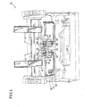
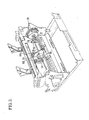
- Figure 5 is a view in perspective of operating mechanical portions of the transport mechanism;
- Figure 6 is a partial view from the left side of the view in Figure 5, according to the arrow designated Fig. 6, 7, 8, 9, 10, 11, showing relationships between the various shafts and rollers;
- Figure 7 is a partial view in accordance with Figure 6 depicting the apparatus with a flat object in position between the rollers;
- Figure 8 is a partial view in accordance with Figure 6 in which an opened passbook having its binder ridge aligned horizontally is shown by dashed lines in position to be drawn through the rollers;
- Figure 9 is a partial view in accordance with Figure 8 in which a passbook having an number of different thicknesses through different sections is shown by dashed lines in position between the rollers;
- Figure 10 is a partial view in accordance with Figures 8 or 9 in which a passbook, or other bound volume, having an unusually large number of pages is shown by dashed lines to be manageable between rollers aligned according to the present invention; and
- Figure 11 is a partial view in accordance with Figures 8 through 10 in which a passbook having a large number of pages in the first side to contact the rollers is shown midway in passage between the rollers.
- Turning to Figure 1, there is shown a perspective view of an embodiment of the invention taken from the front and showing in solid lines how it relates to other elements of a reading and
printing machine 10, indicated in outline by dashed lines. When a blank passbook or other document is inserted into the machine, a sensor involving a switch arm SA which operates a switch at SW serves to detect the presence of a form and start the machine through interconnections which are not shown. - After the machine starts, digital pulses are supplied under control of a microprocessor (not shown) to a stepping motor (20) (Figure 2) causing the motor to rotate step-by-step.
Motor 20 turns agear 22, to operate abelt 24, apulley 26, ashaft 28 and rollers, or rolls, R2 and R4. Rolls R2 and R4 are best shown in Fig. 4 and are referred to hereinafter either as drive rollers or drive rollers. - The
shaft 28, as is most clearly shown in Figure 5, operates a geartrain including gears 32 and 34 to turn ashaft 36. Shaft 36 drives a linkage formed by gears at 38 and 40 and abelt 42 to turn ashaft 44. Shaft 44 provides a driving force to turn two drive rollers R6 and R81 - Idle rollers R12, R14, R16 and R18 are provided in opposition to respective drive rollers R2, R4, R6 and R8. Springs S2, S4, S6 and S8, which are held under tension by means not shown, provide a bias through arms A2, A4, A6 and A8 to urge each of the idle rollers in a direction such that they exert a force against the corresponding drive rollers or against objects positioned between the drive rollers and the idle rollers. Each of the idle rollers is pivoted independently about one of the
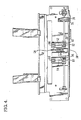
drive shafts - Figure 6 is a partial view further illustrating the manner in which idle rollers R12 and R16 are biased by springs S2 and S6 in tension with arms A2 and A6 into contact with the respective drive rollers R2 and R6. It will be seen also that corresponding elements which are actually hidden in Figure 6, and are indicated by parenthesis, function in the same way. Idle rollers R14 and R18, labeled (R14) and (R18), are biased by springs S4 and S8, under tension through arms A4 and A8 and anchors (not shown), into contact with the respective drive rollers R4 and R8.
- Figure 7 is an illustration of the effect of a flat passbook or a card on the configuration of the rolls. Clearly, when the object to be processed is flat, the flexibility inherent in apparatus according to the present invention is not fully utilized.
- Figure 8 represents the invention in accordance with Figure 7 in which a passbook having a ridge along its center, where it is folded and a seam is sewn, is being processed with the seam moving parallel to the rollers. In this example, the force between the visible rollers R2 and R12 and hidden rollers R4 and R14 will be used in conjunction with that between visible rollers R6 and R16 and hidden rollers R8 and R18 to help drive the passbook to a desired position despite the obstacles presented by the horizontal alignment of the ridge.
- Figure 9 illustrates a situation in which apparatus according to the invention will be able to drive a passbook having sections of unequal thickness in different places. In this case, the passbook is thick on its upper half and is of two different thicknesses on its lower half. Nevertheless, the present invention is able to exert forces on each part of the book to drive it forward, since the idle rollers are independently arranged to exert forces on each part of the book as it goes between them and the drive rollers.
- Figure 10 illustrates the application of apparatus in accordance with the invention to handling passbooks having greater thickness. It will be seen that all the rollers in this case move apart adequately to receive the thick passbook.
- The showing in Figure 11 indicates that a passbook can be handled by embodiments of the invention in which a large end is placed first between the rollers.
- The arrangements of Figures 8 through 11 work better than known prior art arrangements, which involve rollers on a single pair of fixed axes. A single pair of fixed axes, for example, can only operate on a small part of a passbook, either to pull it as by operation of R2, R4, R12 and R14 orto push it as by operation of R6, R8, R16 and R18. Furthermore, the single pair of axes have involved two rigid shafts which are especially unsuited to handle a load such as that illustrated in Figure 9. By contrast, with the present inventive arrangement the rollers first contacted, i.e., R6, R16, R8 and R18, grip the leading edges of the passbook securely regardless of variations in thickness of the parts of the passbook and pull it into a position such as shown in Figures 8 through Figures 11 without difficulty. Subsequently, from the position shown in Figures 8-11, action by the second group of rollers R2, R4, R12 and R14 will forcefully pull the passbook forward while rollers R6, R8, R16 and R18 push the passbook forward thus overcoming the obstacles presented by the ridge in Figure 8, the sharp step on one side as shown in Figure 9, the unusually thick passbook of Figure 10 or the presentation of a thick section to the first set of rollers followed by a thin section as in Figure 11.
Claims (1)
- A drive mechanism for use in transporting bank passbooks and similar objects into position for printing and the like, comprising a first pair of drive rollers (R2 and R4) supported by a first drive shaft (28) to provide driving forces to a first one of the leading front and back surfaces of a selected object and a first pair of idle rollers (R12 and R14) supported by independent shafts to engage the other of said surfaces, said drive and idle rollers being effective to urge the selected object forward along a path to a position enabling a second pair of drive rollers (R6 and R8) supported by a second drive shaft (44) and a second pair of idle rollers (R16 and R18) supported by independent shafts to engage said surfaces of the selected object; biasing means (S2, S4, S6, S8) cooperating with said rollers to enable said rollers to securely engage opposite surfaces of said object; characterised in that said second pair of drive rollers (R6 and R8) provide driving forces to said other of said surfaces while said second pair of idle rollers (R16 and R18) engage said one of said surfaces, in that the independent shafts on which said first pair of idle rollers (R12 and R14) are supported are mounted in first arms (A6 and A8) which are pivotally mounted on said second drive shaft (44) so that said first idle rollers can swing independently about the axis of said second drive shaft, and in that the independent shafts, on which said second pair of idle rollers (R16 and R18) are supported, are mounted in second arms (A2 and A4) which are pivotally mounted on said first drive shaft (28) so that said second idle rollers can swing independently about the axis of said first drive shaft.
Applications Claiming Priority (2)
| Application Number | Priority Date | Filing Date | Title |
|---|---|---|---|
| US85521 | 1979-10-17 | ||
| US06/085,521 US4279413A (en) | 1979-10-17 | 1979-10-17 | Drive mechanisms for passbooks |
Publications (3)
| Publication Number | Publication Date |
|---|---|
| EP0037831A1 EP0037831A1 (en) | 1981-10-21 |
| EP0037831A4 EP0037831A4 (en) | 1982-03-10 |
| EP0037831B1 true EP0037831B1 (en) | 1985-02-20 |
Family
ID=22192173
Family Applications (1)
| Application Number | Title | Priority Date | Filing Date |
|---|---|---|---|
| EP80902318A Expired EP0037831B1 (en) | 1979-10-17 | 1980-10-14 | Drive mechanisms for passbooks |
Country Status (5)
| Country | Link |
|---|---|
| US (1) | US4279413A (en) |
| EP (1) | EP0037831B1 (en) |
| JP (1) | JPH0144615B2 (en) |
| DE (1) | DE3070216D1 (en) |
| WO (1) | WO1981001134A1 (en) |
Families Citing this family (18)
| Publication number | Priority date | Publication date | Assignee | Title |
|---|---|---|---|---|
| US4457656A (en) * | 1981-01-30 | 1984-07-03 | Nolan Systems, Inc. | Stack assembling apparatus and technique |
| FR2519583A1 (en) * | 1982-01-12 | 1983-07-18 | Smh Alcatel | TRAINING AND PRINTING MECHANISM FOR POSTAGE MACHINE |
| SE430323B (en) * | 1982-12-06 | 1983-11-07 | Leif Lundblad | DEVICE FOR LEAKING OUT LEAVES FROM A STOCK OF LEAVES, EXAMPLE BOOKLETS |
| US4605218A (en) * | 1983-10-26 | 1986-08-12 | International Business Machines Corporation | Constant force roll assembly |
| US4671686A (en) * | 1985-12-11 | 1987-06-09 | International Business Machines Corporation | Printer having removable paper feed module |
| JPH02305739A (en) * | 1989-04-28 | 1990-12-19 | Ncr Corp | Transfer mechanism of printing media in bank book printer |
| JP2685290B2 (en) * | 1989-05-19 | 1997-12-03 | 株式会社東芝 | Form handling device |
| JPH03169664A (en) * | 1989-11-30 | 1991-07-23 | Ncr Corp | Bankbook printing machine |
| DE9000255U1 (en) * | 1990-01-11 | 1991-05-16 | Siemens Nixdorf Informationssysteme Ag, 4790 Paderborn, De | |
| JP2763387B2 (en) * | 1990-07-20 | 1998-06-11 | キヤノン株式会社 | Sheet transport device and printer having the sheet transport device |
| US5402998A (en) * | 1993-04-15 | 1995-04-04 | Eastman Kodak Company | O-ring reversing drive coupling |
| JP3156455B2 (en) * | 1993-08-10 | 2001-04-16 | 富士通株式会社 | Magnetic data processing mechanism for booklet medium and booklet medium processing device |
| US5507481A (en) * | 1994-06-10 | 1996-04-16 | Interbold | Automated teller machine passbook transport mechanism |
| US5411433A (en) * | 1994-06-13 | 1995-05-02 | Dynabrade, Inc. | Dust-collecting apparatus |
| US5847719A (en) * | 1995-02-21 | 1998-12-08 | Canon Kabushiki Kaisha | Recording apparatus |
| JP2899234B2 (en) * | 1995-07-27 | 1999-06-02 | キヤノン株式会社 | Recording device |
| JP4486667B2 (en) * | 2007-10-01 | 2010-06-23 | 株式会社沖データ | Medium conveying apparatus and image forming apparatus |
| US20110074089A1 (en) * | 2009-09-30 | 2011-03-31 | Deas Scott H | Media transport |
Family Cites Families (6)
| Publication number | Priority date | Publication date | Assignee | Title |
|---|---|---|---|---|
| US1060276A (en) * | 1912-01-12 | 1913-04-29 | Currier Publishing Company | Delivery feed mechanism for mailing-machines. |
| US2632643A (en) * | 1946-11-05 | 1953-03-24 | Eastman Kodak Co | Apparatus for handling and photographically copying documents |
| US3005537A (en) * | 1959-11-02 | 1961-10-24 | Pitney Bowes Inc | Mail handling apparatus |
| US3211271A (en) * | 1963-11-06 | 1965-10-12 | Burroughs Corp | Line find device |
| US3430947A (en) * | 1967-03-20 | 1969-03-04 | Burroughs Corp | Record card handling and registering apparatus |
| US3618934A (en) * | 1970-05-18 | 1971-11-09 | Addressograph Multigraph | Feed roll assembly |
-
1979
- 1979-10-17 US US06/085,521 patent/US4279413A/en not_active Expired - Lifetime
-
1980
- 1980-10-14 JP JP56500064A patent/JPH0144615B2/ja not_active Expired
- 1980-10-14 WO PCT/US1980/001372 patent/WO1981001134A1/en active IP Right Grant
- 1980-10-14 EP EP80902318A patent/EP0037831B1/en not_active Expired
- 1980-10-14 DE DE8080902318T patent/DE3070216D1/en not_active Expired
Also Published As
| Publication number | Publication date |
|---|---|
| EP0037831A4 (en) | 1982-03-10 |
| JPS56501452A (en) | 1981-10-08 |
| WO1981001134A1 (en) | 1981-04-30 |
| DE3070216D1 (en) | 1985-03-28 |
| EP0037831A1 (en) | 1981-10-21 |
| US4279413A (en) | 1981-07-21 |
| JPH0144615B2 (en) | 1989-09-28 |
Similar Documents
| Publication | Publication Date | Title |
|---|---|---|
| EP0037831B1 (en) | Drive mechanisms for passbooks | |
| CN100473596C (en) | Sheet processing apparatus and image forming apparatus provided with the same | |
| JP5248785B2 (en) | Post-processing apparatus and image forming system having the same | |
| US7052005B2 (en) | Sheet postprocessing apparatus for use with image forming apparatus and folding method | |
| JP2941851B2 (en) | Paper rotation mechanism | |
| EP1006002A2 (en) | Sheet processing apparatus and image forming apparatus | |
| JP4709688B2 (en) | Sheet stacking apparatus and bookbinding apparatus provided with the same | |
| JPS59114257A (en) | Rotary type reverser | |
| JP2786672B2 (en) | Passbook issuing device | |
| EP0769466B1 (en) | Stack transport device | |
| JP3501632B2 (en) | Paper binding device | |
| JP2874899B2 (en) | Book turning device | |
| JPH021052B2 (en) | ||
| JP3473247B2 (en) | Post-processing device for image forming apparatus | |
| JP3351132B2 (en) | Paper transport direction switching device | |
| JPS6037397Y2 (en) | Alignment device in collating machine | |
| JP2999483B2 (en) | Passbook page turning device | |
| JP2514374Y2 (en) | Passbook page break mechanism | |
| JPH0718672Y2 (en) | Application form separation and capture device | |
| JPH0958154A (en) | Page turning-over device for bankbook printer | |
| JPH0211394Y2 (en) | ||
| JP2793256B2 (en) | Passbook issuing device | |
| JP2002347368A (en) | Page turning device and automatic teller machine equipped with the same | |
| JP3677708B2 (en) | Bookbinding equipment | |
| JP4108574B2 (en) | Sheet-like body feeding device |
Legal Events
| Date | Code | Title | Description |
|---|---|---|---|
| PUAI | Public reference made under article 153(3) epc to a published international application that has entered the european phase |
Free format text: ORIGINAL CODE: 0009012 |
|
| 17P | Request for examination filed |
Effective date: 19810408 |
|
| AK | Designated contracting states |
Designated state(s): DE FR GB NL |
|
| GRAA | (expected) grant |
Free format text: ORIGINAL CODE: 0009210 |
|
| AK | Designated contracting states |
Designated state(s): DE FR GB NL |
|
| REF | Corresponds to: |
Ref document number: 3070216 Country of ref document: DE Date of ref document: 19850328 |
|
| ET | Fr: translation filed | ||
| PLBE | No opposition filed within time limit |
Free format text: ORIGINAL CODE: 0009261 |
|
| STAA | Information on the status of an ep patent application or granted ep patent |
Free format text: STATUS: NO OPPOSITION FILED WITHIN TIME LIMIT |
|
| 26N | No opposition filed | ||
| NLS | Nl: assignments of ep-patents |
Owner name: BURROUGHS CORPORATION TE DETROIT, MICHIGAN, VER. S |
|
| PGFP | Annual fee paid to national office [announced via postgrant information from national office to epo] |
Ref country code: NL Payment date: 19911031 Year of fee payment: 12 |
|
| PG25 | Lapsed in a contracting state [announced via postgrant information from national office to epo] |
Ref country code: NL Effective date: 19930501 |
|
| NLV4 | Nl: lapsed or anulled due to non-payment of the annual fee | ||
| PGFP | Annual fee paid to national office [announced via postgrant information from national office to epo] |
Ref country code: GB Payment date: 19940927 Year of fee payment: 15 |
|
| PGFP | Annual fee paid to national office [announced via postgrant information from national office to epo] |
Ref country code: FR Payment date: 19941012 Year of fee payment: 15 |
|
| PGFP | Annual fee paid to national office [announced via postgrant information from national office to epo] |
Ref country code: DE Payment date: 19941027 Year of fee payment: 15 |
|
| PG25 | Lapsed in a contracting state [announced via postgrant information from national office to epo] |
Ref country code: GB Effective date: 19951014 |
|
| GBPC | Gb: european patent ceased through non-payment of renewal fee |
Effective date: 19951014 |
|
| PG25 | Lapsed in a contracting state [announced via postgrant information from national office to epo] |
Ref country code: FR Effective date: 19960628 |
|
| PG25 | Lapsed in a contracting state [announced via postgrant information from national office to epo] |
Ref country code: DE Effective date: 19960702 |
|
| REG | Reference to a national code |
Ref country code: FR Ref legal event code: ST |