EP0037691A2 - Holder assembly for an indexable insert for use in a cutting tool - Google Patents
Holder assembly for an indexable insert for use in a cutting tool Download PDFInfo
- Publication number
- EP0037691A2 EP0037691A2 EP81301350A EP81301350A EP0037691A2 EP 0037691 A2 EP0037691 A2 EP 0037691A2 EP 81301350 A EP81301350 A EP 81301350A EP 81301350 A EP81301350 A EP 81301350A EP 0037691 A2 EP0037691 A2 EP 0037691A2
- Authority
- EP
- European Patent Office
- Prior art keywords
- insert
- cutting tool
- support member
- platform
- screw
- Prior art date
- Legal status (The legal status is an assumption and is not a legal conclusion. Google has not performed a legal analysis and makes no representation as to the accuracy of the status listed.)
- Granted
Links
Images


Classifications
-
- B—PERFORMING OPERATIONS; TRANSPORTING
- B23—MACHINE TOOLS; METAL-WORKING NOT OTHERWISE PROVIDED FOR
- B23B—TURNING; BORING
- B23B27/00—Tools for turning or boring machines; Tools of a similar kind in general; Accessories therefor
- B23B27/14—Cutting tools of which the bits or tips or cutting inserts are of special material
- B23B27/16—Cutting tools of which the bits or tips or cutting inserts are of special material with exchangeable cutting bits or cutting inserts, e.g. able to be clamped
- B23B27/1603—Cutting tools of which the bits or tips or cutting inserts are of special material with exchangeable cutting bits or cutting inserts, e.g. able to be clamped with specially shaped plate-like exchangeable cutting inserts, e.g. chip-breaking groove
- B23B27/1611—Cutting tools of which the bits or tips or cutting inserts are of special material with exchangeable cutting bits or cutting inserts, e.g. able to be clamped with specially shaped plate-like exchangeable cutting inserts, e.g. chip-breaking groove characterised by having a special shape
-
- B—PERFORMING OPERATIONS; TRANSPORTING
- B23—MACHINE TOOLS; METAL-WORKING NOT OTHERWISE PROVIDED FOR
- B23B—TURNING; BORING
- B23B2200/00—Details of cutting inserts
- B23B2200/16—Supporting or bottom surfaces
- B23B2200/165—Supporting or bottom surfaces with one or more grooves
-
- B—PERFORMING OPERATIONS; TRANSPORTING
- B23—MACHINE TOOLS; METAL-WORKING NOT OTHERWISE PROVIDED FOR
- B23B—TURNING; BORING
- B23B2205/00—Fixation of cutting inserts in holders
- B23B2205/16—Shims
-
- Y—GENERAL TAGGING OF NEW TECHNOLOGICAL DEVELOPMENTS; GENERAL TAGGING OF CROSS-SECTIONAL TECHNOLOGIES SPANNING OVER SEVERAL SECTIONS OF THE IPC; TECHNICAL SUBJECTS COVERED BY FORMER USPC CROSS-REFERENCE ART COLLECTIONS [XRACs] AND DIGESTS
- Y10—TECHNICAL SUBJECTS COVERED BY FORMER USPC
- Y10T—TECHNICAL SUBJECTS COVERED BY FORMER US CLASSIFICATION
- Y10T407/00—Cutters, for shaping
- Y10T407/22—Cutters, for shaping including holder having seat for inserted tool
- Y10T407/227—Cutters, for shaping including holder having seat for inserted tool with separate means to fasten tool seat to holder
-
- Y—GENERAL TAGGING OF NEW TECHNOLOGICAL DEVELOPMENTS; GENERAL TAGGING OF CROSS-SECTIONAL TECHNOLOGIES SPANNING OVER SEVERAL SECTIONS OF THE IPC; TECHNICAL SUBJECTS COVERED BY FORMER USPC CROSS-REFERENCE ART COLLECTIONS [XRACs] AND DIGESTS
- Y10—TECHNICAL SUBJECTS COVERED BY FORMER USPC
- Y10T—TECHNICAL SUBJECTS COVERED BY FORMER US CLASSIFICATION
- Y10T407/00—Cutters, for shaping
- Y10T407/23—Cutters, for shaping including tool having plural alternatively usable cutting edges
Landscapes
- Engineering & Computer Science (AREA)
- Mechanical Engineering (AREA)
- Cutting Tools, Boring Holders, And Turrets (AREA)
- Perforating, Stamping-Out Or Severing By Means Other Than Cutting (AREA)
- Details Of Cutting Devices (AREA)
Abstract
Description
- This invention relates to a holder assembly for an indexable insert for use in a metal cutting tool. More particularly, a holder assembly is disclosed having a support member connected to the cutter body,. and including a platform having interlocking key members extending therefrom. A planar indexable insert is provided with receiving grooves for interehgaging the keys of the support member. A screw connects the indexable insert to the support member through a pair of registered apertures therein. The interlocking key and groove arrangement functions to inhibit undesirable rotation of the insert about the axis of the screw during use of the cutting tool.
- Cutting tools in the prior art, such as end mill cutting tools or rotatable milling tools, have been provided with indexable inserts to substantially increase the utility of the tool. More . specifically, prior to the use of indexable inserts, the replaceable blades employed had only a single sharpened edge. To reduce manufacturing costs, an indexable insert, formed from tungsten carbide material, was developed having a plurality of sharpened cutting edges. In use, when a cutting edge beomes dull, the indexable insert is merely rotated such that a fresh sharpened edge is positioned to extend outwardly from the cutter in an active cutting position.
- To maximize the number of cutting edges on a single insert, it is preferable that the insert be symmetrical in configuration to permit indexing and mounting of the insert in a variety cf orientations. Thus, the prior art inserts may be square, circular, triangular, pentagonal, hexagonal or octagonal (multi-faceted) in configuration so as to be readily indexed and mounted to expose a fresh sharpened cutting edge.
- The cutter bodies which were adapted to receive the indexable inserts of the prior art are generally provided with pockets adapted to receive the inserts, which include a platform area 'and one or more side walls. The indexable insert is inserted in one of the pockets and is oriented such that one of the planar surfaces thereof abuts the platform surface of the pocket of the cutter-body. In addition, the side walls of the pocket are adapted to abut and brace one or more of the inactive sides of the insert. By this arrangement, the side walls prevent the insert from rotating about its central axis during the use of the cutting tool. Preventing shifting or rotating of the insert during use is required such that desired axial and radial rake angle, as well as the lead angle of the cutting edge is maintained.
- As can be appreciated, the tooling or machining of the insert pockets in a tool body is difficult and time consuming and thus, relatively expensive. The side walls of the pocket must be formed with relatively high structural rigidity to prevent the breakdown of the cutter during operation. In addition, the number of pockets which may be formed in a cutting tool of a given size is limited and thus, the number of inserts which may be placed around the circumference of the tool is correspondingly limited.
- Accordingly, the present invention attempts to provide an improved holder assembly for an indexable insert which functions to restrict the unwanted rotational movement of the insert during the operation of the cutter.
- The present invention also attempts to provide a new and improved holder assembly for an:indexable insert which eliminates the need for side walls of a receiving pocket.
- Further the present invention attempts to provide a holder assembly for an indexable insert which will allow the mounting of two or more inserts in close proximity, since the need for the side walls of the pocket are eliminated. By this arrangement, the number of inserts which may be mounted on a tool of a given size is increased.
- The present invention provides a holder assembly for an indexable insert for use in conjunction with a cutting tool. The holder assembly includes a support member which is connected to the cutting tool and includes a platform portion. The support member further includes a threaded aperture which is disposed normal to the plane of the platform. The platform portion is provided with a first interlocking means for engagement with the indexable insert. In the preferred embodiments of the subject invention, the first interlocking means consists of at least one key member which extends from the platform of the support member.
- The holder assembly further includes a generally planar indexable insert having a central aperture disposed therein which is perpendicular to the planar surfaces of the insert. The planar insert is mounted on the support member such that one of the planar surfaces thereof is in abutting relationship with the platform portion of the support member with the apertures therein being in register. The planar surface of the indexable insert which is in abutting relationship with the platform portion of the support member includes a second interlocking means adapted to be interengaged with the first interlocking means of the support member. In the preferred embodiments, the second interlocking means includes at least one receiving groove which is adapted to be inter- engaged with the key members of the support member.
- The indexable insert is maintained in abutting relationship with the platform of the support member by a screw which extends through registered apertures therein and is threadably engaged with the aperture in the support member, and by this arrangement, the first and second interlocking means remain interengaged. The interengagement between the keys and groove functions to restrict unwanted rotational movement of the insert about its central axis during the operation of the cutting tool. Thus, the desirable axial and radial rakes and lead angles of the insert may be maintained during the operation of the cutting tool without the need for side wall locators in the cutting tool pocket. To index the insert, the user has merely to loosen the screw and rotate the insert. By retightening the screw, the interlocking means will become interengaged preventing the unwanted rotation of the insert during use of the tool. In addition to reducing manufacturing costs by eliminating the need for side walls in the pockets, the subject invention may be utilized to permit the mounting of a plurality of indexable inserts in close proximity. More specifically, since the requirements of side wall structures are eliminated, a plurality of indexable inserts may be mounted in close proximity to increase the effectiveness of the cutting tool.
- The present invention will be further described, by way of example only, with reference to the accompanying drawings, in which:-
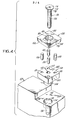
- Figure 1 is an exploded view in perspective of a first embodiment of the holder assembly of the subject invention.
- Figure 2 is a plan view of the first embodiment of the holder assembly of the subject invention.
- Figure 3 is a side elevational view of the first embodiment of the holder assembly of the subject invention.
- Figure 4 is an exploded perspective view of the second embodiment of the holder assembly of the subject invention.
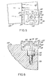
- Figure 5 is a plan view of the second embodiment of the-holder assembly of the subject invention.
- Figure 6 is a side elevational view, partially in section, of the second embodiment of the holder assembly of the subject invention.
- Referring now more specifically to Figures 1-3, a first embodiment of the holder assembly of the subject invention is illustrated. Generally, the holder assembly consists of a
support member 20 which is adapted to be connected to atool body 22. Thesupport member 20 is intended to be interengaged with a generally square, planar indexable insert 24., Ascrew 26 is.provided for fastening theindexable insert 24 to thesupport member 20. - Turning now more specifically to the
tool body 22, a generallyplanar pocket area 30 is provided having ahole 32 therein to allow for the connection of thesupport member 20 to thetool body 22. Thepocket area 30 is undercut from thesurface 34 of the cutting tool to provide the desired clearance angle for the cutting edge of theindexable insert 24. While the subject invention is shown used in conjunction with a -'block style cutting tool, it may readily be adapted for use with a generally circular milling cutter that rotates about a predetermined axis. - The
support member 20 generally matches the configuration of theinsert 24, that is, square in the subject embodiment and includes a planar platform area 40 and a threadedcentral aperture 42 disposed normal to the plane of the platform. Acylindrical connector 44 is provided which extends downwardly from the side of the support member opposed to the platform 40. The diameter of thecylindrical connector 44 is substantially equal to the diameter of theaperture 32 provided in the cutter body. By this arrangement, the interconnection between the support member and the" tool holder orcutter body 30 may be achieved by press fitting thecylindrical connector 44 intoaperture 32 of thetool body 22. The'connection of thesupport member 20 to thetool body 22 may be achieved through various other mechanical expedients, for example, a screw extending through both thetool body 22 and thecylindrical connector 44 in a direction perpendicular to the longitudinal axis of thecylindrical connector 44. In the alternative, thesupport member 20 can be formed integrally with thetool body 22. However, it is apparent-that the mounting method used must function to prevent thesupport member 20 from rotating relative to thetool body 22. - In the first embodiment of the subject invention, the interlocking means of the
support member 20 consists of a plurality of generallyrectangular keys support member 20. In the illustrated embodiment of the holder assembly, the rectangular keys are paired, with the longitudinal axis of the first pair ofrectangular keys rectangular keys 54, 58 extending along a second line, which is perpendicular to the first line. The rectangular keys are thus disposed in a generally cross-like symmetrical configuration, surrounding thecentral apertutee 42 and extending to the side edges of thesupport member 20. The rectangular keys of thesupport member 20 are adapted to be A interengaged with receiving grooves formed in the indexable insert, as more fully described hereinafter. - As illustrated in Figure 1, the
indexable insert 24 is provided with a generally planar, square configuration. The overall configuration of theinsert 24 is that of a conventional positive insert wherein the dimensions of uppersquare surface 60 are slightly greater then the dimensions of the lowersquare surface 62. By this arrangement, the rake faces 64 of the insert are angled to improve the cutting ability of the insert. Acentral aperture 66 is provided which is disposed normal to theplanar surfaces insert 24. Theaperture 66 is formed with a generally frusto-conical portion 68 adjacent the upperplanar surface 60, which is adapted to receivescrew 26. - In accordance with the subject invention, a
standard insert 24 is modified by forming a second interlocking means on the lowerplanar surface 62 thereof. In the illustrated embodiment, the second interlocking means includes a generally cross-shaped receivinggroove 70 having dimensions sufficient to receive the rectangular keys 52-56. As illustrated in Figure 2 and 3, the receivinggroove 70 interfits with the key members 52-56, thereby locking the insert and preventing it from rotational movement about thecentral aperture 66. - The
lower surface 62 of theinsert 24 is maintained in abutting relationship with the platform 40 of thesupport member 20 byscrew 26. The latter extends through theaperture 66 ininsert 24 and is threadably engaged within threadedaperture 42.Screw 26 consists of a flattenedtop portion 72 having a hexagonalcentral indentation 74 to allow for the tightening of thescrew 26 by a suitable wrench or driver. Theshaft portion 76 of the screw is generally cylindrical in configuration while thehead portion 78 of thescrew 26, between theshaft 76 and the flattenedtop portion 72, is generally frusto-conical in configuration. By this arrangement, when the screw is tightened into the threadedaperture 42; the frusto-conical head portion 78 coacts with the frusto-conical area 68 ofhole 66 ininsert 24 in a wedge-like manner, such that the insert is properly seated onsupport member 20. More specifically any initial misalignment prior to the insertion of the screw will be corrected as the screw is tightened. -As illustrated in Figure 3, it is preferred that thescrew 26 be tightened until the flattenedtop 72 is coplanar with theupper surface 60 of theinsert 24. In this embodiment of the subject invention,cylindrical connector 44 is of sufficient length to receive the entire shaft of the screw which extends below theinsert 24. After tightening thescrew 26, theinsert 24 will be securely locked in abutting relation with the platform 40 of thesupport member 20. Further, the keys of the support member are interfit and engaged with the receivinggroove 70 of theinsert 24. The secure interengagement functions to prevent the rotational shifting of the insert during the operation of the tool. - To index the insert, screw 26 is loosened an amount sufficient to disengage the interlocking keys and groove to permit the rotation of the insert. The
screw 26 is then retightened to interengage the opposed interlocking key members 52-58 and receivinggroove 70. Preferably, the key members 52-58 and thegroove 70, are symnetrical in configuration to permit the complete interengagement therebetween in each different orientation. Of course, when the insert bei, employed is not intended to be indexed, the interlocking means need only be matched, rather than symmetrically formed. - Turning now to Figures 4-6, the second embodiment the holder assembly of the subject invention is illustrated and includes a
support member 120 adapted to be connected to atool body 122. Asindexable insert 124 is provided, as well as ascrew 126 having substantially the same configuration as thescrew 26 in the first embodiment of the subject invention. - Turning more specifically to the
tool body 122, aplanar pocket area 130 is provided having a configuration which aids in regulating the orientation of theinsert 124 relative to thetool body 122. Ahole 132 is provided in thepocket area 130 which includes alarge diameter portion 134 and a smaller centrally located threadedaperture portion 136. The threadedaperture portion 136, is adapted to receive the end ofscrew 126, thereby providing an alternate means for connecting the holder assembly,as more fully described hereinafter. -
Support member 120, which matches the insert shape, in this embodiment is square in configuration and includes aplanar platform area 140 and acentral clearance aperture 142. Acylindrical connector 144 is provided on the lower surface of thesupport member 120, and has a diameter substantially equal to thelarger diameter portion 134 ofhole 132 intool body 122.Cylindrical connector 144 is shorter in length than thecylindrical connector 44 of the first embodiment of the subject invention. Thesupport member 120 is connected to thetool body 122 by press fittingcylindrical connector 144 in thelarge diameter portion 134 ofhole 132. Theclearance aperture 142 insupport member 120 is thereby disposed in register with the threadedaperture portion 136 ofhole 132. By this arrangement, the portion of thescrew 126 which extends below thecylindrical connector 144 engages threadedaperture 136 provided in thetool body 122. - In the second embodiment of the subject invention,
support member 120 is provided with an alternative form of interlocking means, and more specifically, is provided with .four symmetrically arranged,-cylindricalkey members platform area 140. While the cylindrical key members 152-158 are illustrated as separate units in the exploded view of Figure 4, they are preferably formed integrally with thesupport member 120 in a manner similar to that illustrated in the first embodiment of the subject invention. In the alternative, fourholes square platform 140 which are adapted to receive cylindricalkey members insert 124. -
Insert 124 has a configuration similar to a standard industry insert and includes an upperplanar surface 160 and a lowerplanar surface 162 of slightly smaller dimensions, thereby defining inclined side rake surfaces 164. Acentral aperture 166 is provided having a frusto-conical portion 168 adjacent theupper surface 160. In accordance with the subject invention, a second interlocking means is provided on the lower surface of theinsert 124 and consists of a symmetrically disposed cross-shaped receivinggroove 170. Receivinggroove 170 is adapted to interengage with the cylindrical keys 152-158 of thesupport member 120. In the second embodiment of the ! subject invention, and as illustrated in Figures 4 and 5, the receivinggroove 170 terminates short of the edges or faces 164 of the insert. Preferably, key members 152-158 are disposed to interengage with the outermost portions of the receivinggroove 170 as most clearly illustrated in Figure 5. By positioning the cylindrical key members 152-158 in the above described manner, maximum resistance to the rotational movement of the insert may be achieved. - Similar to the first embodiment, the
lower surface 162 of theinsert 124 is maintained in abutting relationship with thesupport member 120 by means ofscrew 126.Screw 126 includes a flattenedtop surface 172 and ahexagonal indentation 174. Theshaft 176 of the screw is generally cylindrical in configuration and thehead portion 178 is frusto-conical in configuration. As in the first embodiment, the frusto-conical head 178 coacts with the frusto-conical opening 168 ofaperture 166, in a wedge-like manner, during the tightening of thescrew 126 to properly seat theinsert 124. Thescrew 126 extends throughaperture 166 as well as through theclearance aperture 142 of the support member, and beyondcylindrical connector 144 and is threadably engaged with threadedaperture 136. As in the first embodiment, theinsert 124 may be indexed simply by loosening thescrew 126 and rotating theinsert 124 to expose a new cutting edge. Thereafter, thescrew 126 is retightened to lock theinsert 124 and prevent any unwanted rotational movement. - Accordingly, there is provided a new and improved holder assembly for an indexable, metal cutting tool. The holder assembly consists of a support member which'is connected to the cutting tool and includes an upper platform surface and a central threaded aperture disposed normal to the plane of the platform. The platform includes a first interlocking means which in the preferred embodiments consists of a plurality of symmetrically arranged upstanding key members. ; A generally planar indexable insert having a central aperture therein is disposed in abutting relationship with the platform of the support member. The planar surface of the insert which is abutting the platform surface of the support member includes a second interlocking means which, in the preferred embodiment, consists of a symmetrically arranged receiving groove capable of interengagement with the upstanding key members of the support member. A screw is provided which extends through and is threadably engaged with the apertures in the holder assembly. The screw functions to maintain the indexable insert in abutting relationship with the platform of the support member, whereby the interlocking means remain interengaged thereby restricting the unwanted rotational movement of the insert during the use of the cutting tool. The above described holder assembly functions to maintain the insert in the desired orientation without the necessity of providing side wall retaining means in an insert pocket of a tool body. By this arrangement, cutting tools may be produced at a substantially reduced cost and in addition, a plurality of inserts may be placed in a cutting tool in close proximity, since the need for complex pocket arrangements has been eliminated.
- It is to be understood that changes may be made in the particular embodiments of the invention in light of the above teachings, but that they will fall within the scope and spirit of the subject invention as defined by the appended claims. For example, although the invention has been described with reference to inserts of generally square configuration, the invention may also be embodied in systems wherein the inserts are of triangular, pentagonal, circular, hexagonal or octagonal configuration, and wherein the inserts may be of a negative or positive rake along the edges thereof. Still further, the interlocking means in the form of the grooves and key members may be provided on one or both of the opposed planar surfaces of the insert when the latter is of a negative rake configuration.
Claims (15)
Priority Applications (1)
| Application Number | Priority Date | Filing Date | Title |
|---|---|---|---|
| AT81301350T ATE10592T1 (en) | 1980-04-07 | 1981-03-27 | HOLDER ASSEMBLY FOR AN INDEXABLE CUTTING INSERT IN A CUTTING TOOL. |
Applications Claiming Priority (2)
| Application Number | Priority Date | Filing Date | Title |
|---|---|---|---|
| US137998 | 1980-04-07 | ||
| US06/137,998 US4315706A (en) | 1980-04-07 | 1980-04-07 | Holder assembly for an indexable insert for use in a cutting tool |
Publications (3)
| Publication Number | Publication Date |
|---|---|
| EP0037691A2 true EP0037691A2 (en) | 1981-10-14 |
| EP0037691A3 EP0037691A3 (en) | 1982-04-28 |
| EP0037691B1 EP0037691B1 (en) | 1984-12-05 |
Family
ID=22479982
Family Applications (1)
| Application Number | Title | Priority Date | Filing Date |
|---|---|---|---|
| EP81301350A Expired EP0037691B1 (en) | 1980-04-07 | 1981-03-27 | Holder assembly for an indexable insert for use in a cutting tool |
Country Status (8)
| Country | Link |
|---|---|
| US (1) | US4315706A (en) |
| EP (1) | EP0037691B1 (en) |
| JP (1) | JPS56152506A (en) |
| AT (1) | ATE10592T1 (en) |
| AU (1) | AU6906381A (en) |
| BR (1) | BR8102070A (en) |
| DE (1) | DE3167547D1 (en) |
| ZA (1) | ZA812087B (en) |
Cited By (20)
| Publication number | Priority date | Publication date | Assignee | Title |
|---|---|---|---|---|
| DE2739455A1 (en) * | 1977-07-15 | 1979-01-18 | Houdaille Industries Inc | METHOD FOR AUTOMATICALLY OPERATING A MACHINE ARRANGEMENT AND SUCH A MACHINE TOOL ARRANGEMENT |
| DE3402547A1 (en) * | 1984-01-26 | 1985-08-08 | Hartmetall-Werkzeugfabrik Paul Horn GmbH, 7400 Tübingen | Exchangeable cutting body, especially for an internal-recessing and circular tool |
| DE3405211A1 (en) * | 1984-02-14 | 1985-08-14 | Walter Kieninger GmbH, 7630 Lahr | Cutting tool for machining |
| DE3446455A1 (en) * | 1984-12-20 | 1986-06-26 | Otto 7210 Rottweil Dieterle | Turning tool with throw-away cutting-tool tip |
| AT382542B (en) * | 1984-05-25 | 1987-03-10 | Friedl & Co E | CUTTING TOOL WITH A HARD MATERIAL CUTTING BOARD |
| EP0300172A2 (en) * | 1987-07-24 | 1989-01-25 | Gte Valenite Corporation | Device to prevent rotation of round cutting tool inserts |
| EP0517156A1 (en) * | 1991-06-03 | 1992-12-09 | Diametal Ag | Cutting tool, specially tool for automatic lathes |
| WO1994014558A1 (en) * | 1992-12-28 | 1994-07-07 | Krupp Widia Gmbh | Metal-cutting tool |
| WO1996023614A1 (en) * | 1995-01-30 | 1996-08-08 | Kennametal Inc. | Plunge and face milling cutter with universal insert seats |
| WO1997011806A1 (en) * | 1995-09-25 | 1997-04-03 | Sandvik Aktiebolag | Fastening arrangement for cutting inserts and a cutting insert intended for such an arrangement |
| DE29615412U1 (en) * | 1996-09-04 | 1998-01-08 | Schrammel Helmut Dipl Ing Fh | Knife for a knife head |
| DE29615408U1 (en) * | 1996-09-04 | 1998-01-08 | Schrammel Helmut Dipl Ing Fh | Tool unit |
| WO1998030349A1 (en) * | 1996-12-23 | 1998-07-16 | Sandvik Aktiebolag (Publ) | Cutting insert and holder for metal cutting machining |
| WO1998039122A1 (en) * | 1997-03-05 | 1998-09-11 | Sandvik Aktiebolag (Publ) | Tool holder for cutting inserts |
| WO2001054848A1 (en) * | 2000-01-27 | 2001-08-02 | Sandvik Aktiebolag | Slotting cutter and cutting insert there to |
| EP1524053A2 (en) * | 2003-10-16 | 2005-04-20 | Sandvik Aktiebolag | A cutting tool, a part thereof, as well as a method for the manufacture of such a cutting tool |
| US7476061B2 (en) | 2005-06-27 | 2009-01-13 | Sandvik Intellectual Property Ab | Turning tool and an indexable turning insert, as well as an attachment for such turning tools |
| EP2617505A1 (en) * | 2012-01-20 | 2013-07-24 | Sandvik Intellectual Property AB | A hole-making tool |
| EP3025813A1 (en) * | 2014-11-28 | 2016-06-01 | Sandvik Intellectual Property AB | A tool for chip removing machining and a cutting insert |
| EP2590749A4 (en) * | 2010-07-07 | 2017-06-28 | BMH Technology Oy | Blade bit for crusher rotor |
Families Citing this family (56)
| Publication number | Priority date | Publication date | Assignee | Title |
|---|---|---|---|---|
| JPS58109204A (en) * | 1981-12-18 | 1983-06-29 | Toshiba Corp | Throwaway tip |
| US4586855A (en) * | 1982-06-21 | 1986-05-06 | J. P. Tool Limited | Face milling cutter |
| US4525110A (en) * | 1983-05-18 | 1985-06-25 | Stojan Stojanovski | Indexable ball nose end mill |
| JPS62114803A (en) * | 1985-11-11 | 1987-05-26 | Mitsubishi Metal Corp | Throw away type cutting tool |
| US4770219A (en) * | 1986-07-15 | 1988-09-13 | Blackwell Jr George T | Adzer head assembly |
| US4906145A (en) * | 1987-04-13 | 1990-03-06 | L. R. Oliver & Company, Inc. | Replaceable cutter blade |
| JP2513494Y2 (en) * | 1988-03-03 | 1996-10-09 | 三菱マテリアル株式会社 | Throw-away tip |
| JPH01138507U (en) * | 1988-03-09 | 1989-09-21 | ||
| JP2573098Y2 (en) * | 1991-06-28 | 1998-05-28 | 三菱マテリアル株式会社 | Indexable cutting tools |
| IL112818A (en) * | 1995-02-28 | 1999-10-28 | Iscar Ltd | Tool holder having a grooved seat |
| US5647701A (en) * | 1995-12-13 | 1997-07-15 | Tempel; Daryl K. | Multiple spindle screw machine box tool insert holder |
| US5893683A (en) * | 1997-04-29 | 1999-04-13 | Ingersoll Cutting Tool Company | Indexable insert router |
| US5893315A (en) * | 1997-06-10 | 1999-04-13 | L&P Property Management Company | Notching apparatus and blade for tube severing machine |
| DE19848045C2 (en) * | 1998-10-17 | 2002-01-31 | Fette Wilhelm Gmbh | Insert milling cutters |
| DE10040910A1 (en) * | 2000-08-18 | 2002-02-28 | Widia Gmbh | cutting insert |
| US20040187653A1 (en) * | 2003-03-28 | 2004-09-30 | Terry Chunn | Rotatable seat for cutting tool insert |
| DE10317760B4 (en) * | 2003-04-17 | 2005-08-25 | Walter Ag | Milling tool and cutting plate for such |
| US7004689B2 (en) * | 2004-01-09 | 2006-02-28 | Kennametal Inc. | High-speed milling cutter and insert |
| US7070363B2 (en) | 2004-07-15 | 2006-07-04 | Kennametal Inc. | Cutting insert for high-speed milling cutter |
| DE102005006589A1 (en) * | 2005-02-11 | 2006-08-24 | Sandvik Intellectual Property Ab | Indexable insert and insert holder |
| US20060284469A1 (en) * | 2005-06-02 | 2006-12-21 | Pride Outdoor Products Group, Inc. | Furniture connector |
| DE202005012862U1 (en) * | 2005-08-12 | 2006-12-21 | Kennametal Widia Produktions Gmbh & Co. Kg | cutting tool |
| DE102006052701A1 (en) * | 2006-01-09 | 2007-07-26 | Ceramtec Ag Innovative Ceramic Engineering | Form-fitting mounted cutting plate on a support plate |
| JP5076438B2 (en) * | 2006-01-30 | 2012-11-21 | 三菱マテリアル株式会社 | Insert-type cutting tool and method of fixing insert in insert-type cutting tool |
| SE0600876L (en) * | 2006-04-20 | 2007-10-21 | Sandvik Intellectual Property | Tools and inserts for chip separating machining with primary and secondary meshes with rotationally symmetrical shape |
| IL178813A (en) * | 2006-10-23 | 2010-06-30 | Iscar Ltd | Tangential cutting insert having a base protrusion seating arrangement |
| SE530808C2 (en) * | 2007-01-31 | 2008-09-16 | Sandvik Intellectual Property | Tools for chip separating machining, as well as cutting and basic body for this |
| IL185048A (en) * | 2007-08-05 | 2011-07-31 | Iscar Ltd | Cutting tool and cutting insert therefor |
| DE102008037915B3 (en) | 2008-08-14 | 2009-08-13 | Kennametal Inc. | Indexable insert |
| KR101606935B1 (en) * | 2009-07-09 | 2016-03-28 | 대구텍 유한회사 | Assembly of double-sided indexable cutting insert and reinforced part |
| WO2011021104A1 (en) * | 2009-08-16 | 2011-02-24 | Carmex Precision Tools Ltd. | Insert, support, tool, and method |
| US8388272B2 (en) * | 2009-09-09 | 2013-03-05 | Kennametal Inc. | High speed milling cutter with tapered pin |
| US8573903B2 (en) * | 2009-11-03 | 2013-11-05 | Kennametal Inc. | Round cutting insert with anti-rotation feature |
| US8657539B2 (en) | 2011-03-28 | 2014-02-25 | Kennametal Inc. | Round cutting insert with reverse anti-rotation feature |
| DE102012001732B4 (en) | 2012-01-31 | 2022-11-10 | Kennametal Inc. | Tool head for a modular shank tool, shank tool with such a tool head and manufacturing method for a tool head |
| US8696264B2 (en) * | 2012-01-31 | 2014-04-15 | Kennametal Inc. | Modular cutting insert and method of making same |
| USD709110S1 (en) | 2012-04-24 | 2014-07-15 | Kennametal Inc. | Cutting insert |
| US8858130B2 (en) | 2012-04-24 | 2014-10-14 | Kennametal Inc. | Indexable circular cutting insert |
| DE102012017025B4 (en) * | 2012-08-28 | 2018-05-30 | Kennametal Inc. | Tool holder for a cutting insert and assembly with such a tool holder |
| US9120154B2 (en) * | 2013-02-14 | 2015-09-01 | Iscar, Ltd. | Single-sided square-shaped indexable cutting insert and cutting tool |
| US9120156B2 (en) * | 2013-03-26 | 2015-09-01 | Iscar, Ltd. | Rhombus-shaped indexable cutting insert and cutting tool |
| US9481038B2 (en) * | 2013-12-11 | 2016-11-01 | Iscar, Ltd. | Cutting insert having a dovetail anti-slip arrangement |
| EP2883640B1 (en) * | 2013-12-13 | 2017-05-17 | Sandvik Intellectual Property AB | Cutting tool with abutment members and toolholder and cutting insert therefor |
| EP3153260B1 (en) * | 2015-10-09 | 2018-05-23 | Sandvik Intellectual Property AB | Turning insert and method |
| JP6708183B2 (en) * | 2017-08-10 | 2020-06-10 | 株式会社タンガロイ | Cutting insert and cutting tool |
| CN109530748B (en) * | 2017-09-21 | 2024-02-20 | 杨东佐 | Drilling device and multi-station drilling equipment thereof |
| CN107599818A (en) * | 2017-10-19 | 2018-01-19 | 上海汽车变速器有限公司 | Hybrid power double-clutch speed changer |
| CN108057676A (en) * | 2018-02-05 | 2018-05-22 | 爱思恩梯(苏州)机床有限公司 | A kind of automobile gearbox gear cleans detection production line automatically |
| CN108533643B (en) * | 2018-05-29 | 2024-04-09 | 陕西法士特齿轮有限责任公司 | Series hydraulic retarder |
| CN109625776B (en) * | 2019-02-19 | 2023-09-12 | 何其佳 | Chain, sprocket system and conveying system |
| US11453065B2 (en) * | 2019-05-24 | 2022-09-27 | Iscar, Ltd. | Cutting insert having lower anti-slip recess, insert holder and cutting tool |
| US11154941B2 (en) * | 2019-08-12 | 2021-10-26 | Woodpeckers, Llc | Method and apparatus for milling pen blanks |
| USD955452S1 (en) | 2019-08-12 | 2022-06-21 | Woodpeckers, Llc | Pen mill cutter head |
| JP6940832B1 (en) * | 2020-09-07 | 2021-09-29 | 株式会社タンガロイ | Rolling tool |
| CN113815495A (en) * | 2021-10-29 | 2021-12-21 | 奇瑞商用车(安徽)有限公司 | System and method for improving low-temperature cruising ability of electric automobile |
| CN116395085B (en) * | 2023-06-08 | 2023-12-15 | 江苏力盛船舶设备制造有限公司 | Folding gangway ladder |
Citations (4)
| Publication number | Priority date | Publication date | Assignee | Title |
|---|---|---|---|---|
| US3121939A (en) * | 1957-01-18 | 1964-02-25 | O K Tool Co Inc | Cutting tool with indexable bit |
| DE1552334A1 (en) * | 1966-11-19 | 1969-12-18 | Hans Heinlein | Indexable inserts in a tangential cutting arrangement with detent locking |
| DE1950718A1 (en) * | 1968-10-08 | 1970-11-26 | Diagrit Grinding Company Ltd | Cutting tool |
| US3629919A (en) * | 1969-09-17 | 1971-12-28 | David J Trevarrow Jr | Tool and tool holder assembly |
Family Cites Families (10)
| Publication number | Priority date | Publication date | Assignee | Title |
|---|---|---|---|---|
| US1460030A (en) * | 1922-12-21 | 1923-06-26 | Mattson Julius | Milling-machine cutter |
| US2289344A (en) * | 1941-04-28 | 1942-07-14 | Forest City Bit & Tool Co | Tool |
| US2877535A (en) * | 1955-06-10 | 1959-03-17 | O K Tool Co Inc | Chip breaker for turning machines |
| US3376763A (en) * | 1965-11-19 | 1968-04-09 | Halliburton Co | Boring tools |
| NL158735B (en) * | 1973-10-05 | 1978-12-15 | Ehgartner Fa Hans | GRASS PLATE FOR A CYLINDRICAL ROTATABLE RASP. |
| SU634855A1 (en) * | 1976-09-06 | 1978-11-30 | Горьковский Завод Фрезерных Станков | Cutting tool |
| US4077735A (en) * | 1976-10-14 | 1978-03-07 | General Electric Company | Cutting tool and insert assembly |
| US4083644A (en) * | 1977-04-04 | 1978-04-11 | Kennametal Inc. | Tool holder |
| US4209047A (en) * | 1978-06-28 | 1980-06-24 | Weill Theodore C | Debarker toe assembly |
| US4189264A (en) * | 1978-09-15 | 1980-02-19 | Fansteel Inc. | Cutting insert and chip control assembly |
-
1980
- 1980-04-07 US US06/137,998 patent/US4315706A/en not_active Expired - Lifetime
-
1981
- 1981-03-27 EP EP81301350A patent/EP0037691B1/en not_active Expired
- 1981-03-27 AT AT81301350T patent/ATE10592T1/en active
- 1981-03-27 ZA ZA00812087A patent/ZA812087B/en unknown
- 1981-03-27 DE DE8181301350T patent/DE3167547D1/en not_active Expired
- 1981-04-03 BR BR8102070A patent/BR8102070A/en unknown
- 1981-04-03 AU AU69063/81A patent/AU6906381A/en not_active Abandoned
- 1981-04-07 JP JP5127181A patent/JPS56152506A/en active Pending
Patent Citations (4)
| Publication number | Priority date | Publication date | Assignee | Title |
|---|---|---|---|---|
| US3121939A (en) * | 1957-01-18 | 1964-02-25 | O K Tool Co Inc | Cutting tool with indexable bit |
| DE1552334A1 (en) * | 1966-11-19 | 1969-12-18 | Hans Heinlein | Indexable inserts in a tangential cutting arrangement with detent locking |
| DE1950718A1 (en) * | 1968-10-08 | 1970-11-26 | Diagrit Grinding Company Ltd | Cutting tool |
| US3629919A (en) * | 1969-09-17 | 1971-12-28 | David J Trevarrow Jr | Tool and tool holder assembly |
Cited By (33)
| Publication number | Priority date | Publication date | Assignee | Title |
|---|---|---|---|---|
| DE2739455A1 (en) * | 1977-07-15 | 1979-01-18 | Houdaille Industries Inc | METHOD FOR AUTOMATICALLY OPERATING A MACHINE ARRANGEMENT AND SUCH A MACHINE TOOL ARRANGEMENT |
| DE3402547A1 (en) * | 1984-01-26 | 1985-08-08 | Hartmetall-Werkzeugfabrik Paul Horn GmbH, 7400 Tübingen | Exchangeable cutting body, especially for an internal-recessing and circular tool |
| DE3405211A1 (en) * | 1984-02-14 | 1985-08-14 | Walter Kieninger GmbH, 7630 Lahr | Cutting tool for machining |
| AT382542B (en) * | 1984-05-25 | 1987-03-10 | Friedl & Co E | CUTTING TOOL WITH A HARD MATERIAL CUTTING BOARD |
| DE3446455A1 (en) * | 1984-12-20 | 1986-06-26 | Otto 7210 Rottweil Dieterle | Turning tool with throw-away cutting-tool tip |
| EP0300172A2 (en) * | 1987-07-24 | 1989-01-25 | Gte Valenite Corporation | Device to prevent rotation of round cutting tool inserts |
| EP0300172A3 (en) * | 1987-07-24 | 1989-12-27 | Gte Valenite Corporation | Device to prevent rotation of round cutting tool inserts |
| CH683827A5 (en) * | 1991-06-03 | 1994-05-31 | Diametal Ag | Cutting tool. |
| EP0517156A1 (en) * | 1991-06-03 | 1992-12-09 | Diametal Ag | Cutting tool, specially tool for automatic lathes |
| WO1994014558A1 (en) * | 1992-12-28 | 1994-07-07 | Krupp Widia Gmbh | Metal-cutting tool |
| WO1996023614A1 (en) * | 1995-01-30 | 1996-08-08 | Kennametal Inc. | Plunge and face milling cutter with universal insert seats |
| AU685697B2 (en) * | 1995-01-30 | 1998-01-22 | Kennametal Inc. | Plunge and face milling cutter with universal insert seats |
| CN1060705C (en) * | 1995-01-30 | 2001-01-17 | 钴碳化钨硬质合金公司 | Plunge and face milling cutter with universal insert seats |
| CN1081503C (en) * | 1995-09-25 | 2002-03-27 | 桑德维克公司 | Fastening arrangement for cutting insert and a cutting insert intended for such an arrangement |
| WO1997011806A1 (en) * | 1995-09-25 | 1997-04-03 | Sandvik Aktiebolag | Fastening arrangement for cutting inserts and a cutting insert intended for such an arrangement |
| AU718678B2 (en) * | 1995-09-25 | 2000-04-20 | Sandvik Intellectual Property Ab | Fastening arrangement for cutting inserts and a cutting insert intended for such an arrangement |
| DE29615412U1 (en) * | 1996-09-04 | 1998-01-08 | Schrammel Helmut Dipl Ing Fh | Knife for a knife head |
| DE29615408U1 (en) * | 1996-09-04 | 1998-01-08 | Schrammel Helmut Dipl Ing Fh | Tool unit |
| WO1998030349A1 (en) * | 1996-12-23 | 1998-07-16 | Sandvik Aktiebolag (Publ) | Cutting insert and holder for metal cutting machining |
| WO1998039122A1 (en) * | 1997-03-05 | 1998-09-11 | Sandvik Aktiebolag (Publ) | Tool holder for cutting inserts |
| CN1098739C (en) * | 1997-03-05 | 2003-01-15 | 桑德维克公司 | Tool holder for cutting inserts |
| KR100732224B1 (en) | 2000-01-27 | 2007-06-27 | 산드빅 인터렉츄얼 프로퍼티 에이비 | Slotting cutter and cutting insert there to |
| WO2001054848A1 (en) * | 2000-01-27 | 2001-08-02 | Sandvik Aktiebolag | Slotting cutter and cutting insert there to |
| US7703359B2 (en) | 2003-10-16 | 2010-04-27 | Sandvik Intellectual Property Ab | Cutting tool component and a method of manufacturing same |
| EP1524053A3 (en) * | 2003-10-16 | 2009-09-16 | Sandvik Intellectual Property AB | A cutting tool, a part thereof, as well as a method for the manufacture of such a cutting tool |
| EP1524053A2 (en) * | 2003-10-16 | 2005-04-20 | Sandvik Aktiebolag | A cutting tool, a part thereof, as well as a method for the manufacture of such a cutting tool |
| US7476061B2 (en) | 2005-06-27 | 2009-01-13 | Sandvik Intellectual Property Ab | Turning tool and an indexable turning insert, as well as an attachment for such turning tools |
| EP2590749A4 (en) * | 2010-07-07 | 2017-06-28 | BMH Technology Oy | Blade bit for crusher rotor |
| EP2617505A1 (en) * | 2012-01-20 | 2013-07-24 | Sandvik Intellectual Property AB | A hole-making tool |
| US9138813B2 (en) | 2012-01-20 | 2015-09-22 | Sandvik Intellectual Property Ab | Hole-making tool |
| EP3025813A1 (en) * | 2014-11-28 | 2016-06-01 | Sandvik Intellectual Property AB | A tool for chip removing machining and a cutting insert |
| WO2016083107A1 (en) * | 2014-11-28 | 2016-06-02 | Sandvik Intellectual Property Ab | A tool for chip removing machining and a cutting insert |
| US10173274B2 (en) | 2014-11-28 | 2019-01-08 | Sandvik Intellectual Property Ab | Tool for chip removing machining and a cutting insert |
Also Published As
| Publication number | Publication date |
|---|---|
| ZA812087B (en) | 1982-07-28 |
| JPS56152506A (en) | 1981-11-26 |
| EP0037691A3 (en) | 1982-04-28 |
| EP0037691B1 (en) | 1984-12-05 |
| US4315706A (en) | 1982-02-16 |
| DE3167547D1 (en) | 1985-01-17 |
| BR8102070A (en) | 1981-10-13 |
| AU6906381A (en) | 1981-10-15 |
| ATE10592T1 (en) | 1984-12-15 |
Similar Documents
| Publication | Publication Date | Title |
|---|---|---|
| US4315706A (en) | Holder assembly for an indexable insert for use in a cutting tool | |
| US6234724B1 (en) | Modular cutting tool assembly | |
| US5382118A (en) | Milling cutter insert | |
| CA2486839C (en) | True helical cutter system | |
| EP0489702B1 (en) | Cutting insert and cutting tool for chip removing machining | |
| US6109838A (en) | Face milling cutter and method of assembling | |
| US6773209B2 (en) | Helical insert and cutter bodies | |
| US4729697A (en) | Milling cutter | |
| KR20050085813A (en) | An indexable cutting insert with chip breaker | |
| EP0300172A2 (en) | Device to prevent rotation of round cutting tool inserts | |
| EP1324848A1 (en) | Milling cutter using inserts of various shapes | |
| US4934880A (en) | End mill cutting tool | |
| CA1160822A (en) | Holder assembly for an indexable insert for use in a cutting tool | |
| JP3368662B2 (en) | Indexable milling tools for lead groove processing | |
| JPH09290306A (en) | Cutter for mounting irregular shape tip | |
| JPS6024495Y2 (en) | Throwaway cutter | |
| JPH031139Y2 (en) | ||
| IL130013A (en) | Modular cutting tool assembly |
Legal Events
| Date | Code | Title | Description |
|---|---|---|---|
| PUAI | Public reference made under article 153(3) epc to a published international application that has entered the european phase |
Free format text: ORIGINAL CODE: 0009012 |
|
| AK | Designated contracting states |
Designated state(s): AT BE CH DE FR GB IT LI NL SE |
|
| 17P | Request for examination filed |
Effective date: 19811110 |
|
| PUAL | Search report despatched |
Free format text: ORIGINAL CODE: 0009013 |
|
| AK | Designated contracting states |
Designated state(s): AT BE CH DE FR GB IT LI NL SE |
|
| ITF | It: translation for a ep patent filed |
Owner name: SAIC BREVETTI S.R.L. |
|
| GRAA | (expected) grant |
Free format text: ORIGINAL CODE: 0009210 |
|
| AK | Designated contracting states |
Designated state(s): AT BE CH DE FR GB IT LI NL SE |
|
| PG25 | Lapsed in a contracting state [announced via postgrant information from national office to epo] |
Ref country code: NL Effective date: 19841205 |
|
| REF | Corresponds to: |
Ref document number: 10592 Country of ref document: AT Date of ref document: 19841215 Kind code of ref document: T |
|
| REF | Corresponds to: |
Ref document number: 3167547 Country of ref document: DE Date of ref document: 19850117 |
|
| PG25 | Lapsed in a contracting state [announced via postgrant information from national office to epo] |
Ref country code: GB Effective date: 19850327 Ref country code: AT Effective date: 19850327 |
|
| NLV1 | Nl: lapsed or annulled due to failure to fulfill the requirements of art. 29p and 29m of the patents act | ||
| PLBI | Opposition filed |
Free format text: ORIGINAL CODE: 0009260 |
|
| EN | Fr: translation not filed | ||
| BERE | Be: lapsed |
Owner name: GENERAL ELECTRIC CY Effective date: 19850327 |
|
| GBPC | Gb: european patent ceased through non-payment of renewal fee | ||
| 26 | Opposition filed |
Opponent name: SANDVIK AKTIEBOLAG Effective date: 19850903 |
|
| PG25 | Lapsed in a contracting state [announced via postgrant information from national office to epo] |
Ref country code: DE Effective date: 19851203 |
|
| RDAG | Patent revoked |
Free format text: ORIGINAL CODE: 0009271 |
|
| STAA | Information on the status of an ep patent application or granted ep patent |
Free format text: STATUS: PATENT REVOKED |
|
| 27W | Patent revoked |
Effective date: 19860302 |
|
| REG | Reference to a national code |
Ref country code: CH Ref legal event code: PL |
|
| GBPR | Gb: patent revoked under art. 102 of the ep convention designating the uk as contracting state | ||
| EUG | Se: european patent has lapsed |
Ref document number: 81301350.5 Effective date: 19870224 |