CN1081503C - Fastening arrangement for cutting insert and a cutting insert intended for such an arrangement - Google Patents
Fastening arrangement for cutting insert and a cutting insert intended for such an arrangement Download PDFInfo
- Publication number
- CN1081503C CN1081503C CN96191102A CN96191102A CN1081503C CN 1081503 C CN1081503 C CN 1081503C CN 96191102 A CN96191102 A CN 96191102A CN 96191102 A CN96191102 A CN 96191102A CN 1081503 C CN1081503 C CN 1081503C
- Authority
- CN
- China
- Prior art keywords
- grooves
- ribs
- cutting insert
- insert
- cutting
- Prior art date
- Legal status (The legal status is an assumption and is not a legal conclusion. Google has not performed a legal analysis and makes no representation as to the accuracy of the status listed.)
- Expired - Lifetime
Links
Images


Classifications
-
- B—PERFORMING OPERATIONS; TRANSPORTING
- B23—MACHINE TOOLS; METAL-WORKING NOT OTHERWISE PROVIDED FOR
- B23B—TURNING; BORING
- B23B27/00—Tools for turning or boring machines; Tools of a similar kind in general; Accessories therefor
- B23B27/14—Cutting tools of which the bits or tips or cutting inserts are of special material
- B23B27/16—Cutting tools of which the bits or tips or cutting inserts are of special material with exchangeable cutting bits or cutting inserts, e.g. able to be clamped
- B23B27/1614—Cutting tools of which the bits or tips or cutting inserts are of special material with exchangeable cutting bits or cutting inserts, e.g. able to be clamped with plate-like cutting inserts of special shape clamped against the walls of the recess in the shank by a clamping member acting upon the wall of a hole in the insert
-
- B—PERFORMING OPERATIONS; TRANSPORTING
- B23—MACHINE TOOLS; METAL-WORKING NOT OTHERWISE PROVIDED FOR
- B23B—TURNING; BORING
- B23B27/00—Tools for turning or boring machines; Tools of a similar kind in general; Accessories therefor
- B23B27/06—Profile cutting tools, i.e. forming-tools
- B23B27/065—Thread-turning tools
-
- B—PERFORMING OPERATIONS; TRANSPORTING
- B23—MACHINE TOOLS; METAL-WORKING NOT OTHERWISE PROVIDED FOR
- B23B—TURNING; BORING
- B23B2200/00—Details of cutting inserts
- B23B2200/04—Overall shape
- B23B2200/0461—Round
-
- B—PERFORMING OPERATIONS; TRANSPORTING
- B23—MACHINE TOOLS; METAL-WORKING NOT OTHERWISE PROVIDED FOR
- B23B—TURNING; BORING
- B23B2200/00—Details of cutting inserts
- B23B2200/08—Rake or top surfaces
- B23B2200/086—Rake or top surfaces with one or more grooves
- B23B2200/087—Rake or top surfaces with one or more grooves for chip breaking
-
- B—PERFORMING OPERATIONS; TRANSPORTING
- B23—MACHINE TOOLS; METAL-WORKING NOT OTHERWISE PROVIDED FOR
- B23B—TURNING; BORING
- B23B2200/00—Details of cutting inserts
- B23B2200/16—Supporting or bottom surfaces
- B23B2200/165—Supporting or bottom surfaces with one or more grooves
-
- B—PERFORMING OPERATIONS; TRANSPORTING
- B23—MACHINE TOOLS; METAL-WORKING NOT OTHERWISE PROVIDED FOR
- B23B—TURNING; BORING
- B23B2200/00—Details of cutting inserts
- B23B2200/36—Other features of cutting inserts not covered by B23B2200/04 - B23B2200/32
- B23B2200/3627—Indexing
-
- B—PERFORMING OPERATIONS; TRANSPORTING
- B23—MACHINE TOOLS; METAL-WORKING NOT OTHERWISE PROVIDED FOR
- B23B—TURNING; BORING
- B23B2205/00—Fixation of cutting inserts in holders
- B23B2205/16—Shims
-
- Y—GENERAL TAGGING OF NEW TECHNOLOGICAL DEVELOPMENTS; GENERAL TAGGING OF CROSS-SECTIONAL TECHNOLOGIES SPANNING OVER SEVERAL SECTIONS OF THE IPC; TECHNICAL SUBJECTS COVERED BY FORMER USPC CROSS-REFERENCE ART COLLECTIONS [XRACs] AND DIGESTS
- Y10—TECHNICAL SUBJECTS COVERED BY FORMER USPC
- Y10T—TECHNICAL SUBJECTS COVERED BY FORMER US CLASSIFICATION
- Y10T407/00—Cutters, for shaping
- Y10T407/19—Rotary cutting tool
- Y10T407/1906—Rotary cutting tool including holder [i.e., head] having seat for inserted tool
- Y10T407/1934—Rotary cutting tool including holder [i.e., head] having seat for inserted tool with separate means to fasten tool to holder
-
- Y—GENERAL TAGGING OF NEW TECHNOLOGICAL DEVELOPMENTS; GENERAL TAGGING OF CROSS-SECTIONAL TECHNOLOGIES SPANNING OVER SEVERAL SECTIONS OF THE IPC; TECHNICAL SUBJECTS COVERED BY FORMER USPC CROSS-REFERENCE ART COLLECTIONS [XRACs] AND DIGESTS
- Y10—TECHNICAL SUBJECTS COVERED BY FORMER USPC
- Y10T—TECHNICAL SUBJECTS COVERED BY FORMER US CLASSIFICATION
- Y10T407/00—Cutters, for shaping
- Y10T407/22—Cutters, for shaping including holder having seat for inserted tool
- Y10T407/2272—Cutters, for shaping including holder having seat for inserted tool with separate means to fasten tool to holder
-
- Y—GENERAL TAGGING OF NEW TECHNOLOGICAL DEVELOPMENTS; GENERAL TAGGING OF CROSS-SECTIONAL TECHNOLOGIES SPANNING OVER SEVERAL SECTIONS OF THE IPC; TECHNICAL SUBJECTS COVERED BY FORMER USPC CROSS-REFERENCE ART COLLECTIONS [XRACs] AND DIGESTS
- Y10—TECHNICAL SUBJECTS COVERED BY FORMER USPC
- Y10T—TECHNICAL SUBJECTS COVERED BY FORMER US CLASSIFICATION
- Y10T408/00—Cutting by use of rotating axially moving tool
- Y10T408/86—Tool-support with means to permit positioning of the Tool relative to support
- Y10T408/885—Tool-support with means to permit positioning of the Tool relative to support including tool-holding clamp and clamp actuator
Landscapes
- Engineering & Computer Science (AREA)
- Mechanical Engineering (AREA)
- Cutting Tools, Boring Holders, And Turrets (AREA)
- Accessories And Tools For Shearing Machines (AREA)
- Joining Of Corner Units Of Frames Or Wings (AREA)
- Turning (AREA)
- Processing Of Stones Or Stones Resemblance Materials (AREA)
- Polishing Bodies And Polishing Tools (AREA)
- Milling Processes (AREA)
- Shearing Machines (AREA)
Abstract
Description
本发明涉及主要在金属的切削加工中把切削镶刃紧固到切削镶刃架上的结构和这一结构中的切削镶刃。The present invention relates to a structure for fastening a cutting insert to a cutting insert holder, mainly in metal cutting, and to a cutting insert in this structure.
公知有多种方法把各种切削镶刃和可分度切削镶刃紧固到刀架上。最常见的是切削镶刃中央有一穿孔,而刀架的镶刃座中有一螺纹孔。然后把一锁紧螺丝穿过镶刃的孔后用合适的转矩旋紧在刀架的该孔中,并且在切削镶刃和支撑底面之间常常设置其中央有一孔的垫板。镶刃座上通常还有两个大致互相垂直的抵靠面或三个抵靠点用来抵靠切削镶刃的两个侧面。Various methods are known for securing various cutting inserts and indexable cutting inserts to tool holders. Most commonly, the cutting insert has a through hole in the center and the holder has a threaded hole in the insert seat. Then a locking screw is passed through the hole of the insert and tightened in the hole of the tool holder with a suitable torque, and a backing plate with a hole in its center is often provided between the cutting insert and the supporting bottom surface. There are usually two abutment surfaces or three abutment points which are generally perpendicular to each other on the insert seat to abut against the two sides of the cutting insert.
这种结构的缺点是镶刃在使用一段时间后很容易产生游隙。另一个缺点是螺丝容易旋得太紧而造成损坏甚至断裂。The disadvantage of this structure is that the insert is prone to play after a period of use. Another disadvantage is that the screws can easily be overtightened and cause damage or even breakage.
其他公知的镶刃架包括夹具或类似紧固结构,它们紧压镶刃的顶面而把镶刃夹紧在镶刃座中。夹具的压力可用一螺丝调节。这种结构用来夹紧没有中心孔的镶刃,比方说分开的各镶刃。Other known edge holders include clamps or similar fastening structures that press against the top surface of the insert to clamp the insert in the insert seat. The pressure of the clamp can be adjusted with a screw. This structure is used to clamp inserts without a center hole, such as separate inserts.
为了防止产生游隙并使切削镶刃固定得更牢,公知的结构把切削镶刃的底面和镶刃座的支撑底面的形状做成可互相啮合的锯齿面。这种结构可见美国专利A-2140941和美国专利A-2453464。但是,这些实施例的一个缺点是镶刃或镶刃架或这两者的锯齿面的磨削成本很高。另一个缺点是,即使切削镶刃在与锯齿垂直的方向上得以紧固,但与两抵靠面完全为平面的情况一样,仍会产生垂直游隙,特别是在进行切削加工过程中易发生振动时。In order to prevent backlash and to secure the cutting insert more firmly, it is known that the bottom surface of the cutting insert and the supporting bottom surface of the insert holder are shaped as serrated surfaces that engage with each other. Such structures are described in US Patent A-2140941 and US Patent A-2453464. However, a disadvantage of these embodiments is the high cost of grinding the serrated faces of the insert or the holder or both. Another disadvantage is that even if the cutting insert is tightened in a direction perpendicular to the teeth, as in the case where the two abutment surfaces are completely planar, there is still vertical play, especially during cutting operations. when vibrating.
美国专利A-4437802公开了如何把一切削镶刃紧固到钻床上,该切削镶刃上有两个凹槽,而钻床的支撑面上相应有两个与凹槽密配并占据其整个横截面的肋条。问题仍然是容易产生轴向游隙,特别是在钻床受到振动时。而且,为了获得所需的配合精度,需要对肋条或凹槽进行成本很高的磨削加工。U.S. Patent A-4437802 discloses how to fasten a cutting insert to a drill press. There are two grooves on the cutting insert, and there are two corresponding grooves on the support surface of the drill press that fit closely with the grooves and occupy the entire transverse direction of the drill press. Sectional ribs. The problem remains that it is prone to axial play, especially when the drill press is subject to vibration. Furthermore, costly grinding of the ribs or grooves is required in order to obtain the required fit accuracy.
此外,DE-A-3533125公开了一种铣刀,其中,切削镶刃和刀架互相以锯齿面抵靠而更牢固地连接。这一结构以及上述专利申请的实施例的缺点是镶刃在要转位到新的切削刃时其转动无法小于半圈。而且,需要对刀架的锯齿面进行成本很高的精加工。Furthermore, DE-A-3533125 discloses a milling cutter in which the cutting insert and the tool holder are more firmly connected with serrations abutting against each other. A disadvantage of this construction and of the embodiment of the above-mentioned patent application is that the insert cannot be turned less than half a turn when it is to be indexed to a new cutting edge. Furthermore, costly finishing of the serrated faces of the tool holder is required.
因此,本发明的主要目的是提供一种紧固切削镶刃的结构,这种结构可非常牢固地固定镶刃从而镶刃不会有丝毫的移动。Therefore, the main object of the present invention is to provide a structure for fastening a cutting insert which fixes the insert so firmly that there is no slight movement of the insert.
本发明的另一个目的是提供一种可把镶刃牢牢固定在至少两个、最好是三个分度位置上的结构。Another object of the present invention is to provide a structure which securely holds the insert in at least two and preferably three indexed positions.
本发明的又一个目的是无需进行费钱费时的磨削便能牢牢固定镶刃而不产生游隙。Yet another object of the present invention is to securely hold the insert without play without the need for costly and time-consuming grinding.
本发明的另一个目的是提供一种可直接紧贴从而牢牢紧固在两个或多个镶刃位置上的切削镶刃。Another object of the present invention is to provide a cutting insert which can be directly abutted to securely fasten at two or more insert locations.
本发明的另一个目的是在镶刃座中无需尺寸精度要求很高的抵靠面或抵靠点。Another object of the invention is to eliminate the need for abutment surfaces or points in the insert seat that require high dimensional accuracy.
为实现上述目的,本发明提供了一种把切削镶刃紧固到镶刃架上的结构,该切削镶刃与该镶刃架之间可有或可无一垫板,该切削镶刃的底面和该垫板或该镶刃架的支撑面的形状做成稳固该切削镶刃的互相配合的肋条和凹槽,其中,该切削镶刃的底面上有凹槽和所述凹槽之间的大致平直部;所述支撑面上有一具有肋条的部分,这些肋条可插入切削镶刃的相应数量的凹槽中,至少一部分平直部用作切削镶刃抵靠该支撑面的没有任何肋条的部分的抵靠面。To achieve the above object, the present invention provides a structure for fastening the cutting insert to the insert holder, there may or may not be a backing plate between the cutting insert and the insert holder, the cutting insert The bottom surface and the support surface of the backing plate or the insert holder are shaped to secure the cooperating ribs and grooves of the cutting insert, wherein the bottom surface of the cutting insert has grooves and said grooves said support surface has a portion with ribs which can be inserted into a corresponding number of grooves of the cutting insert, at least a part of the straight portion serving as the cutting insert against the support surface without any The abutment surface of the portion of the rib.
下面结合附图说明本发明的例示性但非限制性的实施例,附图中:Illustrative but non-limiting embodiments of the present invention are illustrated below in conjunction with the accompanying drawings, in the accompanying drawings:
图1为从上方斜向看去的本发明镶刃紧固结构的分解立体图;Fig. 1 is an exploded perspective view of the insert fastening structure of the present invention viewed obliquely from above;
图2为图1切削镶刃的仰视图;Fig. 2 is the bottom view of Fig. 1 cutting insert;
图3为从上方斜向看去的本发明另一实施例的分解立体图;Fig. 3 is an exploded perspective view of another embodiment of the present invention viewed obliquely from above;
图4为从上方斜向看去的本发明又一实施例的分解立体图;Fig. 4 is an exploded perspective view of another embodiment of the present invention viewed obliquely from above;
图5为从上方斜向看去的本发明又一实施例的分解立体图;Fig. 5 is an exploded perspective view of another embodiment of the present invention viewed obliquely from above;
图6为本发明第一基本实施例的剖面图;Figure 6 is a sectional view of a first basic embodiment of the present invention;
图7为本发明第二基本实施例的剖面图。Fig. 7 is a cross-sectional view of a second basic embodiment of the present invention.
图1示出一钻杆或镶刃架1,其轴部与本发明无关。该架的前部包括一基面2,其上有可插入垫板5底面上的凹槽4中的肋条3。肋条3和凹槽4可按瑞典专利申请9401492-7(即WO95/29026)制作,从而镶刃座中无需后抵靠面或抵靠点。因此,如图1所示,该镶刃座无需任何抵靠面,从而镶刃座的制造大大简化。垫板5用一其外螺纹6A旋入孔9中的垫板螺丝6紧固在基面2上,从而垫板螺丝的螺丝头的底面紧抵抵靠面7。从而凹槽的凸缘面紧抵肋条3的相应凸缘面8,而一方面在垫板的底面与各肋条3之间的表面2A之间、另一方面在垫板的底面与肋条3外部的表面2B之间形成微小间隙。Figure 1 shows a drill rod or
但应指出,肋条3与凹槽4之间的边界层或交界面并不是与本发明有关的边界层。在图1中,对本发明至关重要的边界层为垫板5与切削镶刃10之间的边界层,下面详述这一边界层。It should be pointed out, however, that the boundary layer or interface between the
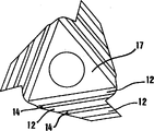
一切削镶刃10、在该例中为一三角形单面镶刃用一紧紧旋入垫板螺丝6的内螺纹6B中的锁紧螺丝11紧固到垫板5的顶面上。镶刃10通常用有涂层或无涂层的硬质合金制成,虽然也可使用其他材料,例如各种陶瓷材料。切削镶刃10的三个角上都有凹槽12,这从图2中可看得更清楚。这样一组大致平行的凹槽与垫板顶面15上的一组相应肋条13互相啮合。该底面上的各凹槽12之间以及最外部凹槽的外部有肋条,这些肋条上有大致平直的表面或靠模14如图6和7左边清楚所示紧抵垫板的不带肋条部的顶面15。A cutting insert 10 , in this example a triangular one-sided insert, is fastened to the top surface of the
图6和7示出本发明的原理,即肋条16及其平直靠模14具有双重作用。一方面肋条16用来楔人并紧固在垫板(若不使用垫板,则为镶刃架)的肋条13之间,另一方面肋条16的平直靠模14用作抵靠垫板(若不使用垫板,则为镶刃架)的顶面15的不带肋条的平直部的抵靠面。从图6(以及图7)中还可看到,肋条13的凸缘面(侧面)13A抵靠凹槽12的凸缘面(侧面)12A。与此相反,肋条13和16的顶面13B和14都不达到相应凹槽底面。Figures 6 and 7 illustrate the principle of the invention that the
为了不造成静态超定,图6中的切削镶刃10的正中部有一不与垫板接靠的更深凹座17。In order not to cause static overdetermination, the cutting insert 10 in FIG. 6 has a
图7示出另一实施例的原理。按照这一原理,镶刃的底面为与肋条的平直靠模14位于同一平面中的平直表面。而在垫板5上有一更深的中部18,以便在镶刃的三个角上实现三点或三区式静态界限分明的抵靠。Fig. 7 shows the principle of another embodiment. According to this principle, the bottom surface of the insert is a flat surface lying in the same plane as the flat former 14 of the rib. On the
图3示出本发明的另一实施例。这一实施例也有一钻杆1’,钻杆上有一前部基面2’和与垫板5’底面上的凹槽4’配合的肋条3’。与图1同样,一可分度切削镶刃10’紧固在垫板5’上。该可分度镶刃10’为双面式,其两面上都有凹槽12’和肋条16’,肋条上有平直靠模14’。从图3镶刃的穿孔中可瞥见,镶刃的反面上与可看到的顶面一样,也有锯齿部。与图1同样,肋条16’啮合在垫板顶面15’的肋条13’之间而稳固工作切削角19’。为了形成一界限分明的抵靠部,垫板顶面上的一部分20可稍稍抬高以便抵靠镶刃的平直肋条靠模14’。从而在该例中镶刃的肋条16’也起到本发明所特有的双重作用。Figure 3 shows another embodiment of the invention. This embodiment also has a drill rod 1' with a front base 2' and ribs 3' cooperating with grooves 4' on the underside of the backing plate 5'. As in Figure 1, an indexable cutting insert 10' is fastened to the backing plate 5'. This indexable insert 10' is a double-sided type, and grooves 12' and ribs 16' are arranged on its two sides, and a straight cam 14' is arranged on the ribs. As can be seen from the perforation of the insert in Figure 3, the opposite side of the insert, like the visible top, also has serrations. As in Figure 1, the ribs 16' engage between the ribs 13' on the backing plate top surface 15' to stabilize the working cutting corner 19'. To form a well-defined abutment, a
按照图1和3,肋条13和13’分别位于工作切削角的底面上,这也是优选实施例。但它们也可设置在非工作角之一上。According to Figures 1 and 3,
本发明也适用于圆形切削镶刃。如图4所示,垫板5”与图1和3同样抵靠钻杆1。切削镶刃10”在该例中也是双面式,从而镶刃的底面与可见顶面相同。镶刃的相反两主要表面上设有若干径向凹槽12”。比方说2-5条、最好是3条这样的凹槽与垫板5”顶面15”上的同样数量的肋条13”啮合,从而凹槽和肋条的侧面以图6和7所示的同样方式进行抵靠。镶刃与垫板之间的任何其他抵靠也可发生在整个表面15”上,但这一表面上最好有两个凸起支撑面21抵靠圆形镶刃上的扇形的平直表面部14”。从而按照这一实施例也能实现静态界限分明的三点或三区式抵靠。The invention is also applicable to round cutting inserts. As shown in Figure 4, the
图5示出一与图4类似的实施例。其不同之处是没有垫板。从而肋条13”和凸起21直接设置在钻杆上。FIG. 5 shows an embodiment similar to FIG. 4 . The difference is that there is no backing plate. The
本领域技术人员显然可看出,由于凹槽12”把镶刃的主平面分成12个扇形,因此只要旋松锁紧螺丝后把图4和5的圆形镶刃转动至少1/12转即可转位到一段新的切削刃22。然后从新上紧锁紧螺丝。Those skilled in the art can clearly see that since the
由上述原理可获得若干优点。与底面为平面的切削镶刃比较可更牢固地紧固各种不同的切削镶刃。而且这较之在镶刃整个底面上制出与垫板顶面上相应凹槽和肋条配合的凹槽和肋条的情况加工精度的要求低。另一个明显的优点是,镶刃在获得更牢固连接的同时可转位到新切削位置上。从上述说明显然可看出,本发明适用于任何形状的镶刃,例如三角形、菱形、正方形、长方形、圆形、六边形和八边形镶刃以及开槽镶刃。Several advantages are obtained from the above principles. Compared with cutting inserts with a flat bottom surface, various cutting inserts can be fastened more firmly. This is also less demanding than the case where the grooves and ribs are formed on the entire bottom surface of the insert to cooperate with the corresponding grooves and ribs on the top surface of the backing plate. Another obvious advantage is that the insert can be indexed to a new cutting position while obtaining a stronger connection. From the foregoing description it is evident that the invention is applicable to any shape of insert such as triangular, diamond, square, rectangular, round, hexagonal and octagonal as well as slotted.
最后可以指出,本发明紧固结构也适用于铣削和钻孔。Finally, it can be pointed out that the fastening arrangement according to the invention is also suitable for milling and drilling.
Claims (20)
Applications Claiming Priority (2)
| Application Number | Priority Date | Filing Date | Title |
|---|---|---|---|
| SE9503307A SE509363C2 (en) | 1995-09-25 | 1995-09-25 | Fixing device removes cutting plates and cutting plate intended for such device |
| SE9503307-2 | 1995-09-25 |
Publications (2)
| Publication Number | Publication Date |
|---|---|
| CN1165492A CN1165492A (en) | 1997-11-19 |
| CN1081503C true CN1081503C (en) | 2002-03-27 |
Family
ID=20399580
Family Applications (1)
| Application Number | Title | Priority Date | Filing Date |
|---|---|---|---|
| CN96191102A Expired - Lifetime CN1081503C (en) | 1995-09-25 | 1996-09-24 | Fastening arrangement for cutting insert and a cutting insert intended for such an arrangement |
Country Status (17)
| Country | Link |
|---|---|
| US (1) | US5810518A (en) |
| EP (1) | EP0805731B1 (en) |
| JP (1) | JPH10509921A (en) |
| KR (1) | KR100430734B1 (en) |
| CN (1) | CN1081503C (en) |
| AT (1) | ATE220590T1 (en) |
| AU (1) | AU718678B2 (en) |
| BR (1) | BR9606642A (en) |
| CA (1) | CA2204638C (en) |
| DE (1) | DE69622376T2 (en) |
| ES (1) | ES2180796T3 (en) |
| IL (1) | IL120771A (en) |
| MX (1) | MX9703821A (en) |
| PL (1) | PL181543B1 (en) |
| RU (1) | RU2164842C2 (en) |
| SE (1) | SE509363C2 (en) |
| WO (1) | WO1997011806A1 (en) |
Cited By (2)
| Publication number | Priority date | Publication date | Assignee | Title |
|---|---|---|---|---|
| CN110253063A (en) * | 2015-06-19 | 2019-09-20 | 株式会社泰珂洛 | Tool bodies and cutting tools |
| TWI698297B (en) * | 2015-11-18 | 2020-07-11 | 以色列商艾斯卡公司 | Cutting tool and triangular-shaped indexable cutting insert therefor |
Families Citing this family (119)
| Publication number | Priority date | Publication date | Assignee | Title |
|---|---|---|---|---|
| US5924826A (en) * | 1994-04-27 | 1999-07-20 | Sandvik Ab | Cutting insert mounted on holder by rib-and-groove coupling |
| SE509339C2 (en) * | 1994-12-08 | 1999-01-11 | Seco Tools Ab | Tools and cutters for chip separating machining |
| SE510851C2 (en) | 1996-12-23 | 1999-06-28 | Sandvik Ab | Cuts and holders for cutting metalworking |
| SE511390C2 (en) * | 1997-03-05 | 1999-09-20 | Sandvik Ab | Device for clamping cutting plates for cutting metal machining |
| SE509540C2 (en) * | 1997-06-30 | 1999-02-08 | Seco Tools Ab | Tool |
| SE514254C2 (en) * | 1997-09-10 | 2001-01-29 | Seco Tools Ab | Chip separation tool |
| DE19847227C2 (en) * | 1998-10-14 | 2001-06-28 | Walter Ag | Cutting tool with a form-fitting insert |
| SE518154C2 (en) | 1999-12-21 | 2002-09-03 | Sandvik Ab | Drill consisting of drill tip portion which is detachably connected to a drill shaft |
| SE515635C2 (en) | 2000-01-27 | 2001-09-17 | Sandvik Ab | Disc cutter and cutter for this |
| IL136564A (en) * | 2000-06-05 | 2003-12-10 | Iscar Ltd | Cutting tool assembly |
| SE520628C2 (en) * | 2001-01-09 | 2003-08-05 | Sandvik Ab | Tools and cutting body for chip separating machining where the coupling surfaces have matching grooves and ridges |
| SE521183C2 (en) * | 2001-03-15 | 2003-10-07 | Sandvik Ab | Cutting holder with means for adjusting the cutting position holder |
| DE10113707C1 (en) * | 2001-03-16 | 2002-10-10 | Mapal Fab Praezision | Tool for machining a workpiece made of high-strength material |
| IL145574A0 (en) * | 2001-09-24 | 2002-06-30 | Iscar Ltd | Cutting tool and cutting insert therefor |
| JP4232438B2 (en) * | 2001-12-07 | 2009-03-04 | 三菱マテリアル株式会社 | Drill |
| SE521579C2 (en) * | 2002-03-21 | 2003-11-11 | Sandvik Ab | Tools and cutting tools for chip separating machining |
| KR100625900B1 (en) * | 2002-06-25 | 2006-09-20 | 엔지케이 스파크 플러그 캄파니 리미티드 | Insert, holder and cutting tool |
| SE525712C2 (en) * | 2002-06-26 | 2005-04-12 | Sandvik Ab | Cutter for drills with chip breakers |
| SE526174C2 (en) * | 2002-07-01 | 2005-07-19 | Seco Tools Ab Publ | Coupling for chip separation tools where the coupling parts can only be mounted in one position |
| SE525583C2 (en) | 2002-07-01 | 2005-03-15 | Seco Tools Ab Publ | Coupling with profiled surfaces for chip separating tools |
| KR100994665B1 (en) * | 2002-07-01 | 2010-11-16 | 쎄코 툴스 에이비 | Couplings, tools, cutting heads and holders for tools for chip removal |
| SE525913C2 (en) * | 2002-12-20 | 2005-05-24 | Seco Tools Ab | Cutter, tool and method of mounting the insert where the insert can be oriented in the desired position |
| SE526109C2 (en) † | 2003-03-17 | 2005-07-05 | Seco Tools Ab | Milling tools and indexable inserts with cooperating projections and recesses |
| US20040187653A1 (en) * | 2003-03-28 | 2004-09-30 | Terry Chunn | Rotatable seat for cutting tool insert |
| DE10330431B3 (en) * | 2003-07-04 | 2005-01-05 | Schunk Ultraschalltechnik Gmbh | welder |
| EP1498200A1 (en) * | 2003-07-16 | 2005-01-19 | Applitec Moutier S.A. | Cutting tool |
| US7156006B2 (en) * | 2003-09-02 | 2007-01-02 | Kennametal Inc. | Method and assembly for rotating a cutting insert during a turning operation and inserts used therein |
| US8573901B2 (en) * | 2003-09-02 | 2013-11-05 | Kennametal Inc. | Assembly for rotating a cutting insert during a turning operation and inserts used therein |
| US6991410B2 (en) * | 2003-10-08 | 2006-01-31 | Kennametal Inc. | Toolholder assembly |
| SE526770C2 (en) * | 2003-10-14 | 2005-11-01 | Sandvik Intellectual Property | Procedure for the manufacture of indexable inserts as well as indexable inserts and cutting tools with such inserts |
| SE526767C2 (en) | 2003-10-16 | 2005-11-01 | Sandvik Intellectual Property | Cutting tool with add-on body with serration surface and procedure for manufacturing cutting tools |
| IL158497A (en) * | 2003-10-20 | 2008-03-20 | Gil Hecht | Deburring tool and cutting insert therefor |
| SE526586C2 (en) * | 2003-11-25 | 2005-10-11 | Sandvik Intellectual Property | Chip separating machining tool including a male / female connection between cutting member and holder part |
| SE526772C2 (en) * | 2003-12-23 | 2005-11-01 | Sandvik Intellectual Property | Cutting tools with serration coupling surfaces and process for making them |
| SE526399C2 (en) * | 2004-01-30 | 2005-09-06 | Sandvik Intellectual Property | Cutting tools and parts therewith with coupling surfaces with grooves and their manufacturing process |
| SE527851C2 (en) | 2004-02-11 | 2006-06-20 | Sandvik Intellectual Property | Cutting tools, cutting tools and parts for cutting tools with serration coupling surfaces |
| US20050173023A1 (en) * | 2004-02-11 | 2005-08-11 | Guofang Cao | Configurations and designs for stump grinding teeth and corresponding holding |
| SE526645C2 (en) * | 2004-02-20 | 2005-10-18 | Sandvik Intellectual Property | groove cutter |
| SE527850C2 (en) * | 2004-02-24 | 2006-06-20 | Sandvik Intellectual Property | Cutting tools and basic body with coupling surfaces provided with ridges |
| US7325471B2 (en) * | 2004-09-07 | 2008-02-05 | Kennametal Inc. | Toolholder and cutting insert for a toolholder assembly |
| SE527613C2 (en) * | 2004-10-15 | 2006-04-25 | Seco Tools Ab | Tool for cutting machining with a base plate with recesses |
| JP4353067B2 (en) * | 2004-10-27 | 2009-10-28 | 三菱マテリアル株式会社 | Insert for thread cutting |
| DE102005007676B3 (en) | 2005-02-19 | 2006-07-13 | Mws Schneidwerkzeuge Gmbh & Co. Kg | Arrangement and securing of cutting plates using grooves cut in the surface of cutting plate and guide rail positioned on it along which cutting plate is tensioned |
| SE528811C2 (en) * | 2005-03-16 | 2007-02-20 | Sandvik Intellectual Property | Cuts and tools for chip separating machining with angled engaging means, and additives for such tools |
| US7040843B1 (en) * | 2005-03-17 | 2006-05-09 | Great Lakes Custom Tool Mfg., Inc. | Flooring hollow back relief cutting tool and method |
| SE528710C2 (en) * | 2005-06-01 | 2007-01-30 | Sandvik Intellectual Property | Indexable cutter with the coupling means arranged on a release surface |
| DE102005032653B3 (en) * | 2005-07-13 | 2006-11-30 | Fette Gmbh | Production process for positive connection between tool insert and carrier |
| DE102006052701A1 (en) * | 2006-01-09 | 2007-07-26 | Ceramtec Ag Innovative Ceramic Engineering | Form-fitting mounted cutting plate on a support plate |
| USD550730S1 (en) | 2006-02-28 | 2007-09-11 | Manchester Tool Company | Cutting insert support/clamp |
| CN101443146A (en) | 2006-02-28 | 2009-05-27 | 钴碳化钨硬质合金公司 | Tool rest assembly |
| USD558802S1 (en) | 2006-02-28 | 2008-01-01 | Kennametal Inc. | Tool holder |
| DE102006017074A1 (en) * | 2006-04-10 | 2007-10-11 | Walter Ag | Shim for double-sided indexable inserts |
| SE0600876L (en) * | 2006-04-20 | 2007-10-21 | Sandvik Intellectual Property | Tools and inserts for chip separating machining with primary and secondary meshes with rotationally symmetrical shape |
| US7390150B2 (en) | 2006-05-03 | 2008-06-24 | Valenite Llc | Cutting tool with adjustable indexable cutting insert |
| US20070274794A1 (en) * | 2006-05-26 | 2007-11-29 | Cirino Thomas J | Oblique angle serration location and drive interface |
| US7357604B2 (en) * | 2006-06-20 | 2008-04-15 | Kennametal Inc. | Indexable cutting insert with positive axial rake angle and multiple cutting edges |
| SE530631C2 (en) * | 2006-12-12 | 2008-07-22 | Sandvik Intellectual Property | Tools and cutters for chip separating machining |
| US7607867B2 (en) * | 2006-12-15 | 2009-10-27 | Sandvik Intellectual Property Ab | Tooling insert with mating surface |
| SE530701C2 (en) * | 2006-12-21 | 2008-08-19 | Sandvik Intellectual Property | Turning tools and lathe inserts where the engaging means of the insert are located in the triangle |
| SE530698C2 (en) * | 2006-12-21 | 2008-08-19 | Sandvik Intellectual Property | Turning tools, as well as the basic body and support plate for such tools |
| SE530808C2 (en) * | 2007-01-31 | 2008-09-16 | Sandvik Intellectual Property | Tools for chip separating machining, as well as cutting and basic body for this |
| DE102007022536A1 (en) * | 2007-05-14 | 2008-11-20 | Kennametal Inc. | Eight cutting insert and tool holder for this |
| DE102007022535A1 (en) * | 2007-05-14 | 2008-11-20 | Kennametal Inc. | Eight cutting insert and tool holder for this |
| FR2916150B1 (en) * | 2007-05-16 | 2009-07-31 | Safety Production Soc Par Acti | TOOL HOLDER AND CENTRAL NOSE CUTTING PLATE |
| KR101472805B1 (en) * | 2007-06-07 | 2014-12-15 | 브이맥스, 인코포레이티드 | adjustable indexable drill |
| IL185048A (en) * | 2007-08-05 | 2011-07-31 | Iscar Ltd | Cutting tool and cutting insert therefor |
| IL185047A (en) * | 2007-08-05 | 2011-09-27 | Iscar Ltd | Cutting tool |
| RU2349425C1 (en) * | 2007-11-27 | 2009-03-20 | Нина Алексеевна Корюкина | Cutting plate and assembled cutting tool (versions) |
| IL188502A (en) * | 2007-12-30 | 2012-05-31 | Iscar Ltd | Cutting insert and cutting tool therefor |
| SE532002C2 (en) * | 2008-02-05 | 2009-09-22 | Sandvik Intellectual Property | Tools for chip separating machining, as well as basic body and cutting for this |
| RU2364476C1 (en) * | 2008-04-21 | 2009-08-20 | Нина Алексеевна Корюкина | Built-up cutting tool (versions) |
| DE102008037915B3 (en) * | 2008-08-14 | 2009-08-13 | Kennametal Inc. | Indexable insert |
| US8454277B2 (en) | 2008-12-18 | 2013-06-04 | Kennametal Inc. | Toolholder and toolholder assembly with elongated seating pads |
| US7922427B2 (en) * | 2008-12-18 | 2011-04-12 | Kennametal Inc. | Toolholder and toolholder assembly with elongated seating pads |
| CN101890511B (en) * | 2009-05-22 | 2012-12-26 | 王登宏 | Double Edge Knife Set |
| WO2011047126A1 (en) * | 2009-10-15 | 2011-04-21 | Sandvik, Inc. | Multiteeth indexable insert with locating means and material removal tool with same |
| DE102009051073A1 (en) * | 2009-10-28 | 2011-05-12 | Kennametal Inc. | Multiple indexable insert for a drilling tool |
| US8573903B2 (en) * | 2009-11-03 | 2013-11-05 | Kennametal Inc. | Round cutting insert with anti-rotation feature |
| US8277153B2 (en) * | 2009-12-02 | 2012-10-02 | Kennametal Inc. | Cutting insert and shim for heavy machining operations |
| KR101154704B1 (en) * | 2010-02-19 | 2012-06-08 | 대구텍 유한회사 | A cutting insert having cutting edges divided by recesses and a milling cutter provided with the same |
| US20110262232A1 (en) * | 2010-04-23 | 2011-10-27 | Chin-Chiu Chen | Lathe blade assembly |
| US9517509B2 (en) * | 2010-12-25 | 2016-12-13 | Kyocera Corporation | Cutting tool and method of manufacturing machined product using the same |
| US8657539B2 (en) | 2011-03-28 | 2014-02-25 | Kennametal Inc. | Round cutting insert with reverse anti-rotation feature |
| JP5754331B2 (en) * | 2011-09-30 | 2015-07-29 | 三菱日立ツール株式会社 | Replaceable cutting tool |
| WO2013051703A1 (en) * | 2011-10-07 | 2013-04-11 | 株式会社タンガロイ | Cutting tool with replaceable blade edge |
| JP2015006698A (en) * | 2011-11-02 | 2015-01-15 | 株式会社タンガロイ | Replaceable cutting tool |
| USD709110S1 (en) | 2012-04-24 | 2014-07-15 | Kennametal Inc. | Cutting insert |
| US8858130B2 (en) * | 2012-04-24 | 2014-10-14 | Kennametal Inc. | Indexable circular cutting insert |
| EP2664399B1 (en) * | 2012-05-15 | 2017-01-04 | VARGUS Ltd. | Cutting tool |
| DE102012017025B4 (en) * | 2012-08-28 | 2018-05-30 | Kennametal Inc. | Tool holder for a cutting insert and assembly with such a tool holder |
| JP6079991B2 (en) * | 2012-09-20 | 2017-02-15 | Toto株式会社 | Static pressure gas bearing |
| US9120154B2 (en) * | 2013-02-14 | 2015-09-01 | Iscar, Ltd. | Single-sided square-shaped indexable cutting insert and cutting tool |
| US9120156B2 (en) * | 2013-03-26 | 2015-09-01 | Iscar, Ltd. | Rhombus-shaped indexable cutting insert and cutting tool |
| DE202013102510U1 (en) * | 2013-06-11 | 2014-06-12 | Pokolm Frästechnik GmbH & Co. KG | Indexable insert for a milling tool for machining workpieces |
| US9375793B2 (en) | 2013-10-29 | 2016-06-28 | Kennametal Inc. | Cutting insert for heavy machining operations |
| US9481038B2 (en) * | 2013-12-11 | 2016-11-01 | Iscar, Ltd. | Cutting insert having a dovetail anti-slip arrangement |
| US9339873B2 (en) * | 2013-12-11 | 2016-05-17 | Iscar, Ltd. | Cutting insert having a dovetail anti-slip arrangement |
| KR101519101B1 (en) * | 2013-12-24 | 2015-05-11 | 한국야금 주식회사 | Insert and tool holder for mounting the same |
| US9421622B2 (en) * | 2014-01-14 | 2016-08-23 | Iscar, Ltd. | Indexable central drill insert and cutting tool therefor |
| CN104227114B (en) * | 2014-07-21 | 2016-08-24 | 株洲钻石切削刀具股份有限公司 | A kind of milling cutter |
| TWI494181B (en) * | 2014-07-28 | 2015-08-01 | 張新添 | Discarded milling cutter structure |
| DE102014119094A1 (en) * | 2014-12-18 | 2016-06-23 | Hartmetall-Werkzeugfabrik Paul Horn Gmbh | Machining tool |
| EP3153260B1 (en) * | 2015-10-09 | 2018-05-23 | Sandvik Intellectual Property AB | Turning insert and method |
| RU2618291C1 (en) * | 2016-02-15 | 2017-05-03 | Нина Алексеевна Корюкина | Cutting plate and cutting tool |
| EP3246117A1 (en) * | 2016-05-20 | 2017-11-22 | Seco Tools Ab | Cutting tool and shim |
| US10556278B2 (en) * | 2016-08-16 | 2020-02-11 | Kennametal Inc. | Tool body for a shell end mill and cutting tool |
| EP3501701B1 (en) * | 2017-12-22 | 2020-07-29 | Ceratizit Austria Gesellschaft m.b.H. | Tool system and method for turning |
| US11484949B2 (en) | 2018-10-10 | 2022-11-01 | Sumitomo Electric Hardmetal Corp. | Cutting insert and cutting tool |
| US11090740B2 (en) * | 2019-02-12 | 2021-08-17 | Iscar, Ltd. | Rotary cutting body having insert pocket with seat surface provided with a plurality of abutment elements and rotary cutting tool |
| EP3702075B1 (en) * | 2019-02-28 | 2023-12-20 | AB Sandvik Coromant | Turning insert for metal cutting |
| EP3738697B1 (en) * | 2019-05-16 | 2023-02-22 | AB Sandvik Coromant | Turning tool for metal cutting |
| EP3738698B1 (en) * | 2019-05-16 | 2022-11-02 | AB Sandvik Coromant | Turning insert for metal cutting, a cutting tool and a method to machine a metal workpiece |
| JP6919824B2 (en) * | 2020-01-15 | 2021-08-18 | 株式会社タンガロイ | Cutting inserts and turning tools using the cutting inserts |
| CN112136623B (en) * | 2020-08-21 | 2022-11-22 | 杨永波 | Factory-type automatic rice planting method |
| US11786982B2 (en) | 2021-04-26 | 2023-10-17 | Kennametal Inc. | Cutting tool comprising toolholder and round cutting insert and method for repositioning the round cutting insert in a pocket of the toolholder |
| US12544841B2 (en) * | 2021-04-26 | 2026-02-10 | Kennametal Inc. | Cutting tool comprising toolholder and round cutting insert and method for repositioning the round cutting insert in a pocket of the toolholder |
| US11717895B2 (en) * | 2021-05-21 | 2023-08-08 | Taegutec Ltd. | Cutting insert and cutting tool assembly including same |
| CN116833436B (en) * | 2023-09-01 | 2023-11-03 | 齐鲁工业大学(山东省科学院) | A gradient stiffness tool shim for machine-clamped indexable tools |
| US20250235933A1 (en) | 2024-01-23 | 2025-07-24 | Iscar, Ltd. | Cutting Tool Having Cutting Insert and Insert Holder With Interface Having a Pair of Male and Female Type Engagement Members |
Citations (2)
| Publication number | Priority date | Publication date | Assignee | Title |
|---|---|---|---|---|
| EP0037691A2 (en) * | 1980-04-07 | 1981-10-14 | General Electric Company | Holder assembly for an indexable insert for use in a cutting tool |
| DE3446455A1 (en) * | 1984-12-20 | 1986-06-26 | Otto 7210 Rottweil Dieterle | Turning tool with throw-away cutting-tool tip |
Family Cites Families (22)
| Publication number | Priority date | Publication date | Assignee | Title |
|---|---|---|---|---|
| DE183293C (en) * | ||||
| US1621226A (en) * | 1923-09-19 | 1927-03-15 | Armstrong Bros Tool Co | Milling cutter |
| US1681675A (en) * | 1925-05-16 | 1928-08-21 | Frank P Miller | Rotary cutter |
| US1629667A (en) * | 1926-10-15 | 1927-05-24 | James D Knipple | Metal-cutting tool |
| SU52003A1 (en) * | 1935-12-14 | 1936-11-30 | С.И. Пономарев | Toolholder for tangential cutter |
| US2140941A (en) * | 1936-10-27 | 1938-12-20 | O K Tool Co Inc | Triple adjustment shankless tool bit and holder therefor |
| US2453464A (en) * | 1945-05-31 | 1948-11-09 | Apex Tool & Cutter Company | Toolholder |
| SE324272B (en) * | 1968-09-24 | 1970-05-25 | Fagersta Bruks Ab | |
| US3829943A (en) * | 1971-02-19 | 1974-08-20 | Fansteel Inc | Threading tool |
| US4437802A (en) * | 1981-09-14 | 1984-03-20 | Hall Jr John J | Boring tool having a detachable cutting blade |
| DE3219019A1 (en) * | 1982-05-19 | 1983-11-24 | Zinner GmbH, 8500 Nürnberg | SINGLE AND MULTIPLE TOOLS |
| DE3333495A1 (en) * | 1983-09-16 | 1985-03-28 | J. Kühn GmbH & Co Präzisionswerkzeug KG, 4270 Dorsten | ROTATING CUTTING TOOL, ESPECIALLY DRILLING HEAD OD. DGL. |
| DE3533125A1 (en) * | 1985-09-17 | 1987-03-19 | Valenite Modco Gmbh | Milling cutter for high-speed milling |
| DE3617119A1 (en) * | 1986-05-22 | 1987-11-26 | Gte Valeron Corp | Adjustable indexable insert |
| SU1526918A1 (en) * | 1987-04-13 | 1989-12-07 | Производственное Объединение "Ворошиловградский Тепловозостроительный Завод Им.Октябрьской Революции" | Polyhedral cutting bit |
| US5028175A (en) * | 1988-03-21 | 1991-07-02 | Gte Valenite Corporation | Indexable insert for roughing and finishing |
| US5236288A (en) * | 1991-11-08 | 1993-08-17 | National Carbide Outlet, Inc. | Cutter with positively locked round inserts |
| RU2028875C1 (en) * | 1992-07-28 | 1995-02-20 | Малое предприятие "Пикон" | Cutter with a replaceable resharpened plate |
| JPH06126511A (en) * | 1992-10-13 | 1994-05-10 | Toyota Motor Corp | Throw-away tip |
| DE4423861A1 (en) * | 1993-05-28 | 1994-12-01 | Holger Groeschel | Fastening device for interchangeable cutting inserts provided with a cylindrical pin |
| US5469902A (en) * | 1993-09-13 | 1995-11-28 | American Knife, Inc. | Chipper knife and knife holder assembly |
| SE504205C2 (en) * | 1994-04-27 | 1996-12-09 | Sandvik Ab | Cut with grooves |
-
1995
- 1995-09-25 SE SE9503307A patent/SE509363C2/en not_active IP Right Cessation
-
1996
- 1996-09-24 ES ES96932128T patent/ES2180796T3/en not_active Expired - Lifetime
- 1996-09-24 KR KR1019970703493A patent/KR100430734B1/en not_active Expired - Lifetime
- 1996-09-24 MX MX9703821A patent/MX9703821A/en unknown
- 1996-09-24 BR BR9606642A patent/BR9606642A/en not_active IP Right Cessation
- 1996-09-24 IL IL12077196A patent/IL120771A/en not_active IP Right Cessation
- 1996-09-24 DE DE69622376T patent/DE69622376T2/en not_active Expired - Lifetime
- 1996-09-24 PL PL96320455A patent/PL181543B1/en unknown
- 1996-09-24 CN CN96191102A patent/CN1081503C/en not_active Expired - Lifetime
- 1996-09-24 EP EP96932128A patent/EP0805731B1/en not_active Expired - Lifetime
- 1996-09-24 JP JP9513350A patent/JPH10509921A/en active Pending
- 1996-09-24 CA CA002204638A patent/CA2204638C/en not_active Expired - Lifetime
- 1996-09-24 US US08/719,976 patent/US5810518A/en not_active Expired - Lifetime
- 1996-09-24 AU AU71028/96A patent/AU718678B2/en not_active Expired
- 1996-09-24 RU RU97110201/02A patent/RU2164842C2/en active
- 1996-09-24 WO PCT/SE1996/001193 patent/WO1997011806A1/en not_active Ceased
- 1996-09-24 AT AT96932128T patent/ATE220590T1/en active
Patent Citations (2)
| Publication number | Priority date | Publication date | Assignee | Title |
|---|---|---|---|---|
| EP0037691A2 (en) * | 1980-04-07 | 1981-10-14 | General Electric Company | Holder assembly for an indexable insert for use in a cutting tool |
| DE3446455A1 (en) * | 1984-12-20 | 1986-06-26 | Otto 7210 Rottweil Dieterle | Turning tool with throw-away cutting-tool tip |
Cited By (2)
| Publication number | Priority date | Publication date | Assignee | Title |
|---|---|---|---|---|
| CN110253063A (en) * | 2015-06-19 | 2019-09-20 | 株式会社泰珂洛 | Tool bodies and cutting tools |
| TWI698297B (en) * | 2015-11-18 | 2020-07-11 | 以色列商艾斯卡公司 | Cutting tool and triangular-shaped indexable cutting insert therefor |
Also Published As
| Publication number | Publication date |
|---|---|
| PL320455A1 (en) | 1997-09-29 |
| ATE220590T1 (en) | 2002-08-15 |
| CN1165492A (en) | 1997-11-19 |
| WO1997011806A1 (en) | 1997-04-03 |
| CA2204638C (en) | 2006-01-31 |
| KR100430734B1 (en) | 2004-09-08 |
| SE9503307D0 (en) | 1995-09-25 |
| SE9503307L (en) | 1997-03-26 |
| CA2204638A1 (en) | 1997-04-03 |
| PL181543B1 (en) | 2001-08-31 |
| ES2180796T3 (en) | 2003-02-16 |
| RU2164842C2 (en) | 2001-04-10 |
| JPH10509921A (en) | 1998-09-29 |
| IL120771A (en) | 2000-07-26 |
| DE69622376T2 (en) | 2003-03-06 |
| BR9606642A (en) | 1997-09-30 |
| MX9703821A (en) | 1997-12-31 |
| IL120771A0 (en) | 1997-09-30 |
| US5810518A (en) | 1998-09-22 |
| EP0805731B1 (en) | 2002-07-17 |
| EP0805731A1 (en) | 1997-11-12 |
| DE69622376D1 (en) | 2002-08-22 |
| AU7102896A (en) | 1997-04-17 |
| SE509363C2 (en) | 1999-01-18 |
| AU718678B2 (en) | 2000-04-20 |
Similar Documents
| Publication | Publication Date | Title |
|---|---|---|
| CN1081503C (en) | Fastening arrangement for cutting insert and a cutting insert intended for such an arrangement | |
| KR101380042B1 (en) | Side locking insert and material removal tool with same | |
| CN1052930C (en) | Tool holder for inserts, including a ribbed clamping surface | |
| CN1139451C (en) | Cutting insert for camshaft milling cutter and corresponding disc milling cutter | |
| US6343898B1 (en) | Cutting insert and holder for metal cutting machining | |
| EP0961666B1 (en) | Cutting insert for chip-breaking machining of metals | |
| US9186732B2 (en) | Cutting insert with grooved surface defining plural support surfaces | |
| CN1092551C (en) | Tool coupling and method for coupling two tool parts | |
| CN102227280B (en) | Clamping mechanism of cutting tool | |
| CN1623709A (en) | Tool for chip-removing machining | |
| CN1251547A (en) | Tool holder for cutting inserts | |
| CN1093449C (en) | Face milling cutter | |
| US7121769B2 (en) | Rotary slot milling cutter and cutting insert therefor | |
| CN1125696C (en) | Cartridges and pressure plates for holding cutting inserts | |
| CN1190916A (en) | Tool for metal cutting | |
| US8356960B2 (en) | Cutting tool and cutting insert therefor | |
| CN1223427C (en) | Insert holder | |
| CN1829581A (en) | Milling cutter and inserts for it | |
| CN1110052A (en) | Rounded cutting insert | |
| CN1747806A (en) | Insert with replaceable head and cutting tool using same | |
| CN1671501A (en) | Disk-shaped or strip-shaped tool | |
| RU2268112C2 (en) | Cutting tool with mutually abutting cutting tips | |
| EP2450138A1 (en) | Cutting insert with grooved surface defining plural support surfaces | |
| JP3724856B2 (en) | Throwaway tip | |
| JP2001138110A (en) | Side cutter |
Legal Events
| Date | Code | Title | Description |
|---|---|---|---|
| C06 | Publication | ||
| PB01 | Publication | ||
| C10 | Entry into substantive examination | ||
| SE01 | Entry into force of request for substantive examination | ||
| C14 | Grant of patent or utility model | ||
| GR01 | Patent grant | ||
| ASS | Succession or assignment of patent right |
Owner name: SANDVIK INTELLECTUAL PROPERTY STOCK CO., LTD. Free format text: FORMER OWNER: SANDVIK AB Effective date: 20050708 |
|
| C41 | Transfer of patent application or patent right or utility model | ||
| TR01 | Transfer of patent right |
Effective date of registration: 20050708 Address after: Sandviken Patentee after: Sandvik AB Address before: Sandviken Patentee before: Sandvik AB |
|
| ASS | Succession or assignment of patent right |
Owner name: SANDVIK INTELLECTUAL PROPERTY RIGHTS CO., LTD. Free format text: FORMER OWNER: SANDVIK INTELLECTUAL PROPERTY STOCK CO., LTD. Effective date: 20051209 |
|
| C41 | Transfer of patent application or patent right or utility model | ||
| TR01 | Transfer of patent right |
Effective date of registration: 20051209 Address after: Sandviken Patentee after: Sandvik Aktiebolag Address before: Sandviken Patentee before: Sandvik AB |
|
| CX01 | Expiry of patent term |
Granted publication date: 20020327 |
|
| EXPY | Termination of patent right or utility model |