EP0037363A1 - Dispositif de protection contre les surtensions - Google Patents
Dispositif de protection contre les surtensions Download PDFInfo
- Publication number
- EP0037363A1 EP0037363A1 EP81730023A EP81730023A EP0037363A1 EP 0037363 A1 EP0037363 A1 EP 0037363A1 EP 81730023 A EP81730023 A EP 81730023A EP 81730023 A EP81730023 A EP 81730023A EP 0037363 A1 EP0037363 A1 EP 0037363A1
- Authority
- EP
- European Patent Office
- Prior art keywords
- elements
- arrester
- level
- housing
- surge arrester
- Prior art date
- Legal status (The legal status is an assumption and is not a legal conclusion. Google has not performed a legal analysis and makes no representation as to the accuracy of the status listed.)
- Granted
Links
Images

Classifications
-
- H—ELECTRICITY
- H01—ELECTRIC ELEMENTS
- H01T—SPARK GAPS; OVERVOLTAGE ARRESTERS USING SPARK GAPS; SPARKING PLUGS; CORONA DEVICES; GENERATING IONS TO BE INTRODUCED INTO NON-ENCLOSED GASES
- H01T4/00—Overvoltage arresters using spark gaps
- H01T4/16—Overvoltage arresters using spark gaps having a plurality of gaps arranged in series
- H01T4/18—Arrangements for reducing height of stacked spark gaps
-
- H—ELECTRICITY
- H01—ELECTRIC ELEMENTS
- H01C—RESISTORS
- H01C7/00—Non-adjustable resistors formed as one or more layers or coatings; Non-adjustable resistors made from powdered conducting material or powdered semi-conducting material with or without insulating material
- H01C7/10—Non-adjustable resistors formed as one or more layers or coatings; Non-adjustable resistors made from powdered conducting material or powdered semi-conducting material with or without insulating material voltage responsive, i.e. varistors
- H01C7/12—Overvoltage protection resistors
-
- H—ELECTRICITY
- H01—ELECTRIC ELEMENTS
- H01T—SPARK GAPS; OVERVOLTAGE ARRESTERS USING SPARK GAPS; SPARKING PLUGS; CORONA DEVICES; GENERATING IONS TO BE INTRODUCED INTO NON-ENCLOSED GASES
- H01T1/00—Details of spark gaps
- H01T1/15—Details of spark gaps for protection against excessive pressure
Definitions
- a surge arrester of this type has become known from CH-PS 304 299.
- the arrester elements are arranged alternately in one of the columns in a plane running perpendicular to the longitudinal axis of the columns as a connection between two columns and then again as an element of another column. This results in an overall helical course with a saving in axial length.
- the object of the invention is to enable a further substantial increase in the packing density of the arrester elements.
- surge arresters in particular for high operating voltages, for. B. 500 kV, can be created, which can be inserted into metal-enclosed, pressurized gas-insulated switchgear without difficulty, but are also suitable for outdoor installation.
- z. B. accommodate three arrester elements in a four-column structure in each level. If one now chooses a version in which the levels are connected by a diverter element, one arrives at a surge arrester which is suitable for arrangement in air or the nitrogen which is frequently used in conventional surge arresters.
- a conductive support body can be used to connect the scaffolding elements of two adjacent levels. This allows the distance between the levels to be reduced and the structure becomes much more compact. This arrangement is particularly suitable for installation in electronegative gas under pressure, for. B. SF 6 , and enables the construction of arresters with favorable dimensions, as are desired for metal-enclosed switchgear.
- the arrangement of a diverter element or a conductive support body between the levels ensures that the flow direction of the current changes from level to level.
- the inductance of the overall arrangement thus becomes a minimum.
- the same property can also be achieved in a modified design in which arrester elements connected in parallel are present in the individual levels.
- control elements such as. B. linear or non-linear control resistors and capacitors
- n-1 arrester elements and a control element can be arranged in each level, the control element being connected between the current supply and discharge lines of each level. In this way, a chain of control elements connected in parallel to the arrester elements is created to equalize the voltage distribution.
- the control element completes the triangular, rectangular or polygonal shape of the planes in such a way that an increase in mechanical strength is achieved. If, on the other hand, it is only a question of increasing the strength, an insulating support body with the dimensions of an arrester element can also be inserted in each plane instead of a control element.
- the scaffolding elements can be designed as hollow bodies.
- the modular construction of the arrester gives good access to the cavity and, if appropriate, fastening elements to be attached there.
- the cavity of the scaffolding elements can be used as a collecting space for gases which can arise as a result of the thermal decomposition of arrester elements if the surge arrester is overloaded.
- the interior spaces of the arrester elements can be connected to the cavities of the scaffolding elements and these can be connected to the surrounding atmosphere through a pressure compensation opening.
- the z. B. by hollow or tubular support body between the arrester elements and the scaffold elements is particularly suitable for surge arresters with a housing that is to be protected against sudden pressure when the arrester is overloaded.
- the hot gases first fill the cavities of the scaffolding elements before they dampen the housing with a time delay.
- the arrangement just described can be made even more effective in that the cavities of the scaffolding elements can be connected to the atmosphere surrounding the housing by means of a crushing membrane when an inadmissible overpressure occurs. In this case, there is no pressure on the housing or any contamination. It can therefore be used again after the defective arrangement of arrester elements has been removed.
- Fig. 1 shows a perspective view of the internal structure of a surge arrester for outdoor installation.
- FIG. 2 also shows in perspective the internal structure of a surge arrester for a compressed gas-insulated, metal-enclosed switchgear.
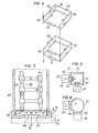
- FIG. 3 shows a scaffolding element as an individual part.
- FIG. 4 A parallel connection of arrester elements is shown schematically in FIG. 4.
- FIG. 5 and 6 show a section of a column structure of arrester elements, one for receiving each Gas-compatible scaffolding element with the adjacent arrester elements.
- Fig. 7 shows a section through an encapsulated surge arrester with crushing membranes.
- the surge arrester 1 shown in FIG. 1 comprises a housing 2 which is designed as a hollow porcelain insulator with shields. In the interior of the housing, a four-pillar structure of arrester elements is arranged between support plates 3 and 4, which are connected to a voltage-side connection 5 or an earth connection 6.
- Each of the columns 10, 11, 12 and 13 is composed of arrester elements 14, insulating support bodies 15 and framework elements 16 in a specific order.
- the arrester elements 14 and the insulating support body 15 have the same length, so that these elements can be combined as desired.
- the further columns 11, 12 and 13 contain insulating support bodies 15 at the same height.
- the open side of the U-shape is located between the columns 10 and 11.
- the connection to the lower level is then likewise established via a scaffold element 16 by means of a conductor element 14, in which the current path through further conductor elements 14 is reversed Direction as in the upper level.
- Another conductor element 14 located in the course of the column 10 establishes the connection with the lower support plate 4, which is connected to the earth connection.
- the other columns contain insulating supporting bodies of the same dimensions, parallel to the lowermost conductor element 14.
- the mentioned arrester elements 14 are preferably voltage-dependent resistors based on zinc oxide.
- the actual resistance body is surrounded by an insulating housing, the dimensions of which are adapted to the insulating support bodies.
- the high mechanical strength of the zinc oxide resistors also makes it possible to dispense with separate insulating housings.
- the resistors are connected directly to the scaffolding elements using suitable connection fittings which are fixedly attached to the resistance body.
- the elimination of the insulating housing increases the volume of the resistance material to be accommodated and improves its cooling.
- a series connection of spark gaps with voltage-dependent resistors can also be provided.
- This can e.g. B. happen that one or more of the arrester elements 14 in Fig. 1 are designed as spark gaps.
- the spark gaps do not need their own gas-tight encapsulation if the structure shown in FIG. 1 is arranged within the housing 2 in an atmosphere which leads to the desired mode of operation of the spark gaps. In a known manner, this can be achieved by filling the housing 2 with nitrogen.
- FIG. 2 shows a further exemplary embodiment of a surge arrester. Similar to FIG. 1, a column structure with four columns 20, 21, 22 and 23 is again selected, which are arranged in the corner points of a square. Likewise, by means of scaffolding elements 24, insulating support body 25 and conductive support body 26 and arrester elements 27 have a uniform structure with a number of planes lying perpendicular to the longitudinal axis of the columns. In contrast to the exemplary embodiment according to FIG. 1, however, no arrester elements are used in the longitudinal direction of the columns, that is to say to connect the planes to one another, but instead only insulating support bodies 25 and conductive support bodies 26 are used alternately. These support bodies are smaller than the corresponding parts in the example according to FIG. 1.
- a spark gap unit 30 which is encapsulated in an insulating housing 31, is used as a further arrester element in the second level from above in addition to the arrester elements 27 consisting of voltage-dependent resistors.
- a different gas than the insulating gas mentioned can be used in the region of the electrodes of the spark gap unit in order to achieve a desired response and extinguishing behavior of the spark gap. Nitrogen is particularly suitable for operating the spark gap. Due to its parallel connection to three of the arrester elements 27, the spark gap unit 30 short-circuits this part of the arrester during the response process.
- a scaffolding element is shown as an individual part in FIG. 3.
- the scaffold element 33 is designed as a cylindrical body and has an upper and a lower cover surface 34 or 35, each with a threaded opening 36 or 37, and on its circumference three threaded openings 40, 41 and 42 at an angle of 90 ° Arrangement of the threaded holes, the scaffold element 33 can be used at any point of the surge arrester shown in FIGS. 1 and 2. If the arrester elements as well as the insulating and conductive support bodies are provided with suitable threaded pins, the surge arresters described can be assembled in a modular manner. Instead of threaded holes, profile holes or simple through holes can also be provided if the scaffolding elements are designed as hollow bodies and the interior for attaching fastening elements, eg. B. pins, nuts or the like, is accessible. For this purpose, the scaffolding element can be formed in two parts by division along a line 43 shown in dashed lines in FIG. 3 in the manner of a pot and a lid.
- arrester elements are respectively connected in series in the planes perpendicular to the longitudinal extension of the columns.
- arrester elements connected in parallel can also be provided, as is shown schematically in FIG. 4.
- the arrester elements 45 are ent here by dashes in the arrangement symbolizing speaking of the four-column structure.
- Two arrester elements are connected in parallel by conductive connections 46.
- Each level of the arrester therefore contains six instead of three arrester elements. If a further increase in the leakage current to be controlled or the energy to be absorbed is desired, more than two arrester elements can be connected in parallel for each level.
- the rest of the arrangement in particular the arrangement of conductive and insulating support bodies between the levels, remains unchanged.
- a control element 73, z. B. a linear or a non-linear resistor or a capacitor is connected, which, in conjunction with the same control elements 73 of the other levels, forms a chain of control elements connected in parallel with the arrester elements 45, which uniformize the voltage distribution.
- control elements can also be connected in parallel.
- surge arresters are not only suitable for arresters with a housing (2 in Fig. 1, 28 in Fig. 2). Rather, the active part itself can be set up as a surge arrester because the multi-column structure with the scaffolding elements can be carried out in a mechanically stable and stable manner. All that is required for outdoor installation is the weatherproof design of the components.
- a device for pressure relief is generally required, which discharges the pressurized hot gases into the outside space when the arrester is overstressed.
- the described column structure of the new trap offers an advantageous option for incorporating a pressure relief system.
- the interior spaces of the scaffolding elements can be used as collecting spaces for the decomposition gases, as shown in FIGS. 5 and 6.
- the interior of the active part can also be used as collecting spaces in this embodiment, which can be provided at a desired location with an opening opening into the surroundings.
- FIG. 5 shows, as a section of an arrester according to FIGS. 1 or 2, an arrester element 45 with a framework element 46 and a subsequent support body 47.
- the arrester element 45 contains within an insulating housing 48 a resistance body 49 which is conductively connected to the scaffolding element 46 by means of a threaded connector 50.
- a threaded connector 50 By screwing the threaded connector 50 into the scaffold element 46, in addition to the electrical and mechanically load-bearing connection, a seal from the environment is also created.
- the gases that occur when the resistance body 49 is overloaded therefore pass through a bore 51 of the threaded connector 50 into a cavity 52 of the scaffold element 46, from where they can spread through the subsequent tubular support body 47 to further scaffold elements.
- a gradual decrease in pressure occurs through a small opening 53 in the framework element 46 achieved.
- further openings can also be made in the other scaffolding elements, not shown.
- the overpressure only gradually takes up the environment and thus any existing housing.
- a crushing membrane can be arranged in a suitable location in the housing, through whose bursting the gases can escape to the outside.
- FIG. 6 which shows a further connection point within the column structure in a representation rotated by 90 ° in relation to FIG. 5
- two arrester elements 54 are directly connected to a scaffold element 55 without a screw connection.
- cylindrical lugs 56 are formed on the scaffold element 55, which receive the ends of the arrester elements 54 like sleeves.
- the connection can e.g. B. by an external thread of the housing of the arrester elements and an internal thread of the lugs 56.
- putty or glue are also suitable for a permanent connection.
- a conductive transition between the arrester elements and the scaffolding elements must be ensured.
- larger cross sections for the passage of gases from the arrester elements into the scaffolding elements can be achieved according to FIG. 6.
- FIG. 7 shows how the gases from an encapsulated arrester are of both insulating and metal encapsulated type can be derived without stressing the housing or the encapsulation in any way.
- the column structure designated overall by 60, is designed to be closed with respect to the interior 61; H. there are no pressure equalization openings in the scaffolding elements.
- the cavities of the support body of the column structure first open with the interposition of crushing membranes 67 in a buffer space 62 which is formed by a lower support plate 63 for the column structure 60 and the end fitting 64 of a housing 65.
- An opening 66 of the end fitting 64 is closed by a further breaking membrane 68. If, after the crushing membranes 67 have responded, gases enter the buffer space 62, the crushing membrane 68 bursts and the gases get directly into the environment without straining the housing 65. Therefore, the housing remains in a clean and reliable condition and can be used again after the defective active part 60 has been removed.
- Fig. 7 is also indicated by dashed lines that the gases can not only exit from the housing 65 in the axial direction according to the direction of arrow 70, but also with a correspondingly selected design of the end fitting 64 also perpendicular to the longitudinal axis of the housing 65 in the direction of Arrow 71 or by deflecting in the direction of arrow 72.
- the surge arresters described can be constructed not only using the zinc oxide resistors mentioned above, which are characterized by a particularly pronounced, non-linear current-voltage characteristic, but also with other resistors suitable for surge arresters, alone or in conjunction with spark gaps connected in series or in parallel. Therefore z.
- Resistors based on silicon carbide can also be used, as well as combinations of different types of resistors or mixed bodies made of different resistance materials.
- arrester elements can also be inserted into the columnar structure, which serve to control the voltage distribution, as is known by Resistors and / or capacitors can be achieved.
- control rings can be used in addition or on their own, particularly in the case of the described arrester without a housing.
Priority Applications (1)
| Application Number | Priority Date | Filing Date | Title |
|---|---|---|---|
| AT81730023T ATE8943T1 (de) | 1980-03-28 | 1981-03-09 | Ueberspannungsableiter. |
Applications Claiming Priority (2)
| Application Number | Priority Date | Filing Date | Title |
|---|---|---|---|
| DE3012744A DE3012744C2 (de) | 1980-03-28 | 1980-03-28 | Überspannungsableiter |
| DE3012744 | 1980-03-28 |
Publications (2)
| Publication Number | Publication Date |
|---|---|
| EP0037363A1 true EP0037363A1 (fr) | 1981-10-07 |
| EP0037363B1 EP0037363B1 (fr) | 1984-08-08 |
Family
ID=6099040
Family Applications (1)
| Application Number | Title | Priority Date | Filing Date |
|---|---|---|---|
| EP81730023A Expired EP0037363B1 (fr) | 1980-03-28 | 1981-03-09 | Dispositif de protection contre les surtensions |
Country Status (10)
| Country | Link |
|---|---|
| US (1) | US4363069A (fr) |
| EP (1) | EP0037363B1 (fr) |
| JP (1) | JPS56152182A (fr) |
| AT (1) | ATE8943T1 (fr) |
| BR (1) | BR8101857A (fr) |
| DD (1) | DD157646A5 (fr) |
| DE (1) | DE3012744C2 (fr) |
| IN (1) | IN152746B (fr) |
| SU (1) | SU1098532A3 (fr) |
| ZA (1) | ZA812066B (fr) |
Cited By (1)
| Publication number | Priority date | Publication date | Assignee | Title |
|---|---|---|---|---|
| EP0092737A1 (fr) * | 1982-04-24 | 1983-11-02 | Hitachi, Ltd. | Parafoudre |
Families Citing this family (7)
| Publication number | Priority date | Publication date | Assignee | Title |
|---|---|---|---|---|
| SE424932B (sv) * | 1980-12-19 | 1982-08-16 | Asea Ab | Ventilavledare |
| DE69031604T2 (de) * | 1989-02-07 | 1998-05-20 | Bowthorpe Ind Ltd | Überspannungsableitervorrichtung |
| RU2191454C2 (ru) * | 2000-06-27 | 2002-10-20 | Открытое акционерное общество "Научно-производственное объединение "Стример" | Импульсный грозовой разрядник для линии электропередачи (варианты) и колонка импульсных разрядников |
| US20060256496A1 (en) * | 2005-05-13 | 2006-11-16 | Clark M C | Methods and apparatuses related to pulsed power |
| US20070159760A1 (en) * | 2005-05-13 | 2007-07-12 | Collins Clark | Methods and Systems Related to Pulsed Power |
| DE102009007067A1 (de) * | 2009-01-29 | 2010-08-05 | Siemens Aktiengesellschaft | Impedanzanordnung mit einem ersten Armaturkörper |
| US10741313B1 (en) * | 2019-02-06 | 2020-08-11 | Eaton Intelligent Power Limited | Bus bar assembly with integrated surge arrestor |
Citations (6)
| Publication number | Priority date | Publication date | Assignee | Title |
|---|---|---|---|---|
| US3144583A (en) * | 1960-11-14 | 1964-08-11 | Westinghouse Electric Corp | Lightining arrester |
| US3155874A (en) * | 1961-08-02 | 1964-11-03 | Westinghouse Electric Corp | Lightning arrester |
| US3412273A (en) * | 1964-10-28 | 1968-11-19 | Westinghouse Electric Corp | High voltage lightning arrester having a plurality of arrester elements |
| US3803524A (en) * | 1970-11-12 | 1974-04-09 | Siemens Ag | Overvoltage arrester with ejectable type ground line |
| FR2389985A1 (fr) * | 1977-05-07 | 1978-12-01 | Mitsubishi Electric Corp | |
| DE2907985A1 (de) * | 1978-03-03 | 1979-09-06 | Hitachi Ltd | Zinkoxidueberspannungsableiter |
Family Cites Families (6)
| Publication number | Priority date | Publication date | Assignee | Title |
|---|---|---|---|---|
| CA538533A (fr) * | 1957-03-19 | M. Opsahl Alert | Parafoudres a haut voltage | |
| US2528127A (en) * | 1946-11-13 | 1950-10-31 | Westinghouse Electric Corp | Lightning arrester |
| US2542805A (en) * | 1948-06-01 | 1951-02-20 | Westinghouse Electric Corp | Lightning arrester |
| US2608600A (en) * | 1949-06-18 | 1952-08-26 | Asea Ab | Arrangement at surge diverters for increasing the discharging ability |
| CH304299A (de) * | 1952-09-11 | 1954-12-31 | Bbc Brown Boveri & Cie | Uberspannungsableiter für hohe Betriebsspannungen. |
| DE1463593B2 (de) * | 1964-04-17 | 1972-03-02 | Siemens AG, 1000 Berlin u 8000 München | Ueberspannungsableiter |
-
1980
- 1980-03-28 DE DE3012744A patent/DE3012744C2/de not_active Expired
-
1981
- 1981-03-09 AT AT81730023T patent/ATE8943T1/de not_active IP Right Cessation
- 1981-03-09 EP EP81730023A patent/EP0037363B1/fr not_active Expired
- 1981-03-25 SU SU3261984A patent/SU1098532A3/ru active
- 1981-03-26 IN IN328/CAL/81A patent/IN152746B/en unknown
- 1981-03-26 DD DD81228624A patent/DD157646A5/de unknown
- 1981-03-27 US US06/248,232 patent/US4363069A/en not_active Expired - Fee Related
- 1981-03-27 BR BR8101857A patent/BR8101857A/pt unknown
- 1981-03-27 JP JP4535781A patent/JPS56152182A/ja active Pending
- 1981-03-27 ZA ZA00812066A patent/ZA812066B/xx unknown
Patent Citations (6)
| Publication number | Priority date | Publication date | Assignee | Title |
|---|---|---|---|---|
| US3144583A (en) * | 1960-11-14 | 1964-08-11 | Westinghouse Electric Corp | Lightining arrester |
| US3155874A (en) * | 1961-08-02 | 1964-11-03 | Westinghouse Electric Corp | Lightning arrester |
| US3412273A (en) * | 1964-10-28 | 1968-11-19 | Westinghouse Electric Corp | High voltage lightning arrester having a plurality of arrester elements |
| US3803524A (en) * | 1970-11-12 | 1974-04-09 | Siemens Ag | Overvoltage arrester with ejectable type ground line |
| FR2389985A1 (fr) * | 1977-05-07 | 1978-12-01 | Mitsubishi Electric Corp | |
| DE2907985A1 (de) * | 1978-03-03 | 1979-09-06 | Hitachi Ltd | Zinkoxidueberspannungsableiter |
Cited By (1)
| Publication number | Priority date | Publication date | Assignee | Title |
|---|---|---|---|---|
| EP0092737A1 (fr) * | 1982-04-24 | 1983-11-02 | Hitachi, Ltd. | Parafoudre |
Also Published As
| Publication number | Publication date |
|---|---|
| ATE8943T1 (de) | 1984-08-15 |
| BR8101857A (pt) | 1981-09-29 |
| DE3012744A1 (de) | 1981-10-22 |
| EP0037363B1 (fr) | 1984-08-08 |
| IN152746B (fr) | 1984-03-24 |
| DD157646A5 (de) | 1982-11-24 |
| US4363069A (en) | 1982-12-07 |
| SU1098532A3 (ru) | 1984-06-15 |
| JPS56152182A (en) | 1981-11-25 |
| DE3012744C2 (de) | 1985-10-10 |
| ZA812066B (en) | 1982-04-28 |
Similar Documents
| Publication | Publication Date | Title |
|---|---|---|
| DE2037921C3 (de) | Blitzschutzeinrichtung | |
| CH656972A5 (de) | Ueberspannungsableiter. | |
| DE1193568B (de) | Durchfuehrung fuer elektrische Geraete, insbesondere Leistungsschalter, die ein gas-foermiges Isoliermittel enthalten | |
| DE3610742A1 (de) | Stuetzisolator | |
| EP0037363B1 (fr) | Dispositif de protection contre les surtensions | |
| EP3271927B1 (fr) | Système de parafoudre | |
| DE1189176B (de) | Giessharzisolierte elektrische Hochspannungs-Schaltanlage mit metallisch leitender, gerdeter Huelle | |
| EP2615703B1 (fr) | Éclateur composé de plusieurs éclateurs individuels commutés en série, se trouvant dans un agencement empilé | |
| WO1994014171A1 (fr) | Dispositif de protection contre les surtensions comportant une resistance en oxyde metallique | |
| EP1603141A1 (fr) | Limiteur de surtensions avec isolation au gaz | |
| DE3426054A1 (de) | Ueberspannungsableiter | |
| DE2843120A1 (de) | Gekapselte blitzschutzvorrichtung | |
| DE3012741C2 (de) | Überspannungsableiter mit einer Säule von Ableiterelementen und Abschirmkörpern | |
| DE2050727C3 (de) | Überspannungsableiteranordnung | |
| EP1273016A1 (fr) | Module avec limiteur de surtension pour une installation a haute tension | |
| DE2912844C2 (de) | Blitzschutzvorrichtung | |
| DE2458376B2 (de) | Hochspannungs-leistungsschalter | |
| EP3659223A1 (fr) | Système comprenant un dispositif de commutation à isolation gazeuse | |
| DE19638746C1 (de) | Elektrische Anlage für den Mittelspannungsbereich | |
| DE2348137A1 (de) | Elektrische hochspannungseinrichtung mit einer metallkapselung und einem ueberspannungsableiter | |
| DE2348136C3 (de) | Elektrisches Gerät für Hochspannung mit einer ein Isoliergas enthaltenden Kapselung aus Metall | |
| EP3131098B1 (fr) | Paratonnerre encapsule | |
| DE3616243C2 (fr) | ||
| DE2827456A1 (de) | Blitzschutzvorrichtung | |
| DE19647736C1 (de) | Hochspannungs-Leistungsschalter mit einem hohlen Isolierstoffstützer |
Legal Events
| Date | Code | Title | Description |
|---|---|---|---|
| PUAI | Public reference made under article 153(3) epc to a published international application that has entered the european phase |
Free format text: ORIGINAL CODE: 0009012 |
|
| AK | Designated contracting states |
Designated state(s): AT CH FR GB LI SE |
|
| 17P | Request for examination filed |
Effective date: 19811016 |
|
| GRAA | (expected) grant |
Free format text: ORIGINAL CODE: 0009210 |
|
| AK | Designated contracting states |
Designated state(s): AT CH FR GB LI SE |
|
| RBV | Designated contracting states (corrected) |
Designated state(s): AT CH FR GB LI SE |
|
| REF | Corresponds to: |
Ref document number: 8943 Country of ref document: AT Date of ref document: 19840815 Kind code of ref document: T |
|
| ET | Fr: translation filed | ||
| PLBE | No opposition filed within time limit |
Free format text: ORIGINAL CODE: 0009261 |
|
| STAA | Information on the status of an ep patent application or granted ep patent |
Free format text: STATUS: NO OPPOSITION FILED WITHIN TIME LIMIT |
|
| 26N | No opposition filed | ||
| PGFP | Annual fee paid to national office [announced via postgrant information from national office to epo] |
Ref country code: AT Payment date: 19860228 Year of fee payment: 6 |
|
| PG25 | Lapsed in a contracting state [announced via postgrant information from national office to epo] |
Ref country code: AT Effective date: 19870309 |
|
| GBPC | Gb: european patent ceased through non-payment of renewal fee | ||
| PG25 | Lapsed in a contracting state [announced via postgrant information from national office to epo] |
Ref country code: SE Effective date: 19880310 |
|
| PG25 | Lapsed in a contracting state [announced via postgrant information from national office to epo] |
Ref country code: LI Effective date: 19880331 Ref country code: CH Effective date: 19880331 |
|
| PG25 | Lapsed in a contracting state [announced via postgrant information from national office to epo] |
Ref country code: GB Effective date: 19881118 |
|
| PG25 | Lapsed in a contracting state [announced via postgrant information from national office to epo] |
Ref country code: FR Free format text: LAPSE BECAUSE OF NON-PAYMENT OF DUE FEES Effective date: 19881130 |
|
| REG | Reference to a national code |
Ref country code: CH Ref legal event code: PL |
|
| REG | Reference to a national code |
Ref country code: FR Ref legal event code: ST |
|
| EUG | Se: european patent has lapsed |
Ref document number: 81730023.9 Effective date: 19881205 |