EP0036977A1 - Tunnel-type furnace - Google Patents
Tunnel-type furnace Download PDFInfo
- Publication number
- EP0036977A1 EP0036977A1 EP81101792A EP81101792A EP0036977A1 EP 0036977 A1 EP0036977 A1 EP 0036977A1 EP 81101792 A EP81101792 A EP 81101792A EP 81101792 A EP81101792 A EP 81101792A EP 0036977 A1 EP0036977 A1 EP 0036977A1
- Authority
- EP
- European Patent Office
- Prior art keywords
- sand
- tunnel
- cup
- furnace according
- area
- Prior art date
- Legal status (The legal status is an assumption and is not a legal conclusion. Google has not performed a legal analysis and makes no representation as to the accuracy of the status listed.)
- Granted
Links
- 239000004576 sand Substances 0.000 claims abstract description 105
- 238000007789 sealing Methods 0.000 claims abstract description 16
- 239000013013 elastic material Substances 0.000 claims description 3
- 230000004048 modification Effects 0.000 claims description 2
- 238000012986 modification Methods 0.000 claims description 2
- 238000006073 displacement reaction Methods 0.000 claims 1
- 239000000463 material Substances 0.000 description 4
- UGFAIRIUMAVXCW-UHFFFAOYSA-N Carbon monoxide Chemical compound [O+]#[C-] UGFAIRIUMAVXCW-UHFFFAOYSA-N 0.000 description 3
- 239000003546 flue gas Substances 0.000 description 3
- 239000007789 gas Substances 0.000 description 3
- 239000011324 bead Substances 0.000 description 2
- 238000010276 construction Methods 0.000 description 2
- 238000001816 cooling Methods 0.000 description 2
- 239000002184 metal Substances 0.000 description 2
- 229910000831 Steel Inorganic materials 0.000 description 1
- 230000001627 detrimental effect Effects 0.000 description 1
- 230000000694 effects Effects 0.000 description 1
- 238000005265 energy consumption Methods 0.000 description 1
- 238000005259 measurement Methods 0.000 description 1
- 238000004064 recycling Methods 0.000 description 1
- 239000012858 resilient material Substances 0.000 description 1
- 239000000565 sealant Substances 0.000 description 1
- 239000003566 sealing material Substances 0.000 description 1
- 230000035939 shock Effects 0.000 description 1
- 239000010959 steel Substances 0.000 description 1
Images


Classifications
-
- F—MECHANICAL ENGINEERING; LIGHTING; HEATING; WEAPONS; BLASTING
- F27—FURNACES; KILNS; OVENS; RETORTS
- F27D—DETAILS OR ACCESSORIES OF FURNACES, KILNS, OVENS, OR RETORTS, IN SO FAR AS THEY ARE OF KINDS OCCURRING IN MORE THAN ONE KIND OF FURNACE
- F27D99/00—Subject matter not provided for in other groups of this subclass
- F27D99/0073—Seals
- F27D99/0076—Furnace car seals, i.e. seals used in continuous furnaces or kilns for preventing gas or heat exchange between heating chamber and the area comprising driving means
-
- F—MECHANICAL ENGINEERING; LIGHTING; HEATING; WEAPONS; BLASTING
- F27—FURNACES; KILNS; OVENS; RETORTS
- F27B—FURNACES, KILNS, OVENS, OR RETORTS IN GENERAL; OPEN SINTERING OR LIKE APPARATUS
- F27B9/00—Furnaces through which the charge is moved mechanically, e.g. of tunnel type; Similar furnaces in which the charge moves by gravity
- F27B9/14—Furnaces through which the charge is moved mechanically, e.g. of tunnel type; Similar furnaces in which the charge moves by gravity characterised by the path of the charge during treatment; characterised by the means by which the charge is moved during treatment
- F27B9/20—Furnaces through which the charge is moved mechanically, e.g. of tunnel type; Similar furnaces in which the charge moves by gravity characterised by the path of the charge during treatment; characterised by the means by which the charge is moved during treatment the charge moving in a substantially straight path tunnel furnace
- F27B9/26—Furnaces through which the charge is moved mechanically, e.g. of tunnel type; Similar furnaces in which the charge moves by gravity characterised by the path of the charge during treatment; characterised by the means by which the charge is moved during treatment the charge moving in a substantially straight path tunnel furnace on or in trucks, sleds, or containers
- F27B9/262—Furnaces through which the charge is moved mechanically, e.g. of tunnel type; Similar furnaces in which the charge moves by gravity characterised by the path of the charge during treatment; characterised by the means by which the charge is moved during treatment the charge moving in a substantially straight path tunnel furnace on or in trucks, sleds, or containers on or in trucks
Definitions
- the invention relates to a tunnel kiln with a sand cup for tunnel kiln cars with a sealing apron extending into the sand cup.
- the seal which is formed from a sand cup and apron, is intended to prevent pressure equalization between the flue gas zone (negative pressure area) and the normal pressure area connected to the tunnel entrance, and thus to prevent the intake of false air and the associated flue gas cooling. In practice, however, this seal is imperfect because there are gaps between the individual tunnel kiln cars through which the pressure equalization takes place.
- the object of the present invention is to provide means which avoid these disadvantages, that is to say that the carriages can be closed tightly without damaging the sealing aprons.
- this object is achieved in that a device for keeping sand free is provided, which temporarily keeps the area free of sand in which the end of the sealing apron of the last car that has entered the furnace facing the tunnel entrance is located when the next tunnel car is connected this last car is run in.
- the problem is solved in such a way that the device comprises, at least in the area concerned, a sealing bar for the apron, which presses against the apron from below with the aid of spring-elastic means when a car drives in.
- Fig. 1 denotes a tunnel kiln and 2 denotes a tunnel kiln car movable in the tunnel.
- the carriage runs by means of wheels 3 on rails 4 laid on the tunnel furnace floor.
- the screw connections 7 and 8 are used to fasten metal sheets 9, 10 which have been turned inside over at their upper ends.
- the sheets form together with the corresponding wall parts channels extending in the longitudinal direction of the furnace, so-called sand cups 11, 12, which are filled with sand.
- the total height of the gutter is approx. 12 cm, with the sand approx. 8 cm high.
- the tunnel kiln cars have a support plate 13 made of steel, which are provided on their sides with so-called aprons 14, 15 projecting downwards. These aprons are designed and arranged so that they extend into the sand bed of the sand cups and thus form a seal.
- a push bar 16 is provided, which is aligned with the support plate end face in a vertical plane; In operation, the individual wagons in the furnace should abut one another with these push beams and thus transmit the pushing force.
- Fig. 3 shows schematically two electric motors 18, 19 which are arranged below the bottom 20 of a sand cup 11 so that their shafts 21, 22 penetrate the bottom vertically and actuate threshing vanes 23 to move the sand away.
- Several such [inrich lines in the longitudinal direction of the cup can be arranged one behind the other.
- Fig. 4 shows a corresponding arrangement in which the motor 25 is arranged on the side of the sand cup. Its shaft 25 'projects horizontally into the sand cup and drives the rotating blades 24 located on both sides of the apron 14.
- Fig. 5 shows an embodiment in which a side channel 26 is attached to the side wall 5 of the tunnel furnace, which is connected via the slot 27 with the bottom region of the sand cup 11.
- a side channel 26 is attached to the side wall 5 of the tunnel furnace, which is connected via the slot 27 with the bottom region of the sand cup 11.
- an elastic hose 28 is fastened tightly, which ends at 29 in the collecting container 30.
- the cross section of the hose is circular and the connection is rotatable. The arrangement is chosen so that the hose 28 also rises to the junction 29.
- In the collecting container there is a vacuum generator which is connected to the interior of the collecting container via the sand filter 31.
- the container volume is selected so that it can accommodate the sand in the affected sand cup area and the incoming sand bow wave of the advancing car.
- the container together with the vacuum generator is mounted pivotably about a horizontal axis 32 through at least 180 0, wherein the bearing is suitably carried out such that the axis of rotation coaxial with the opening-junction extends 29th
- the collecting container 30 is tilted by 180 ° by means of the electric motor 33, so that the sand is returned to the sand cup via the hose 28 and the slot 27.
- a suction fan conveys the sand into a higher-lying reservoir via a slot (27) - which can now run horizontally or even better obliquely from the bottom of the sand cup.
- This reservoir has an outflow opening which can be shut off by means of a slide. In this way, the sand that has been sucked away can be returned to the sand cup after unlocking the last car that has been driven in.
- a second slot is provided in the wall 5, which runs obliquely downwards towards the sand cup and opens out above the normal sand level of the sand cup. This construction ensures that the sand can completely run back into the sand cup.
- a device can be seen in which the affected sand cup area is designed to be laterally tiltable.
- the tiltability can be achieved by any known means; However, it is particularly expedient to make the cup area elastic (rubber channel) and to tilt it into the position shown in dashed lines by means of a motorized adjusting device.
- the entire gutter does not necessarily have to be tilted; with a corresponding cross-section of the cup and not too high a level, it is also sufficient if only part of the channel - e.g. is lowered or tilted from the middle of the sand channel.
- a side channel 26 is also provided in the embodiment according to FIG. 7.
- the side wall 5 is also perforated here with a slot 34, the slot cross section widening conically towards the side channel.
- the slot opening on the sand cup side extends to the bottom of the sand cup 20.
- a tipping chute 35 can be adjusted in height (by means of an electric motor 36 and cable pulley 37).
- the chute 38 is over a elastic hose part 39 attached to the sand cup-side slot opening 40.
- Chute pipe 38 and chute container 41 are again dimensioned so that they can absorb the amount of sand. In the drawn down position of the dump chute, it runs full of sand; in the upper position shown in dashed lines, the sand is tipped back into the sand cup.
- the sand cup bottom 20 is designed to be height-adjustable. For this purpose it is made of rubber. The height adjustment is achieved in that an inflatable chamber 42 is provided on the underside of the sand cup bottom. If gas is blown into the chamber by a compressed gas generator via the connection 43, it fills up and lifts the cup base into the position shown. If the gas is released, the floor sags so far that the apron of the car no longer reaches down into the sand bed.
- the affected area of the sand cup is formed entirely from an elastic groove (FIG. 9), a particularly simple adjustment device is expedient.
- a fastening plate 44 is arranged, which in turn is connected to a downward-pointing toothed rack 45, in which the pinion 46 of a drive motor engages.
- the cup is pulled down in its entirety in the entire affected area, thus achieving the desired effect.
- the sand cup is lifted on the one hand by the elasticity of the material used, but on the other hand expediently with the support of the adjusting device.
- a vibrating device (vibrator) of the usual type is connected, so that it can be lifted without any problems.
- a hydraulic drive or the like can of course also be used.
- adjusting devices are unnecessary because the vibrating device smoothes the sand bow wave and ensures that the sand dodges the approaching apron faces of the adjacent tunnel kiln cars.
- This design has the particular advantage that no control device for controlling the lifting and lowering devices, suction devices, tilting devices and the like. The like. Is necessary because the vibrator can easily run in continuous operation.
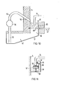
- FIG. 10 shows a device in cross section, in which the bottom of the sand cup in the area concerned has a closable sand outlet.
- the bottom of the sand cup consists of a sheet metal slide 48 that can be moved laterally and laterally in the direction of the double arrow 47.
- the suction pump 54 which acts as a lifting device for the sand, the sand is then fed back to the affected area of the sand cup via the pipe part 55 and the wall slot 56 which runs obliquely downwards towards the sand cup.
- the slot opens at a height that is above the normal sand level in the cup. The sheet is pulled out and pushed back in in the usual way by motor.
- the apron 14 is not sealed by means of sand, but by means of a sealing bar 57.
- This bar is pressed against the lower apron end using spring elastic means, for example coil springs 58, whereby the seal is ensured.
- the bar extends from the tunnel entrance to the "affected" area, where there is no sand for temperature reasons must be used as a sealant.
- the bar In the area of the tunnel entrance, the bar is bent downwards like a skid to allow the apron of an incoming car to slide open.
- an elastic cover 59 eg rubber cover
- the bar itself can be made of resilient material (which then makes covering means unnecessary).
- the trough 11 itself can consist of rubber material which is suspended or supported so tensioned that it presses the bar resiliently upwards.
- a bracket 60 to the beam in the manner of a fastening angle, which in turn carries an elastic lateral sealing lip 61 (bead).
- the beginning of this bead is bent out laterally from the apron entry area so that the apron can be retracted easily.
- a wear layer 62 which consists of sealing material that interacts well with the apron.
- a guide in the bar into which band-shaped and correspondingly profiled wear material can be used (in the manner of a brake rubber for front wheel shock brakes of bicycles).
Landscapes
- Engineering & Computer Science (AREA)
- Mechanical Engineering (AREA)
- General Engineering & Computer Science (AREA)
- Tunnel Furnaces (AREA)
- Furnace Housings, Linings, Walls, And Ceilings (AREA)
- Aerodynamic Tests, Hydrodynamic Tests, Wind Tunnels, And Water Tanks (AREA)
- Manufacture And Refinement Of Metals (AREA)
- Electronic Switches (AREA)
- Hall/Mr Elements (AREA)
- Thermistors And Varistors (AREA)
Abstract
Description
Die Erfindung bezieht sich auf einen Tunnelofen mit Sandtasse für Tunnelofenwagen mit in die Sandtasse reichender Abdichtschürze. Die aus Sandtasse und Schürze gebildete Dichtung soll den Druckausgleich zwischen der Rauchgaszone (Unterdruckbereich) und dem mit dem Tunneleingang in Verbindung stehenden Normaldruckbereich verhindern und so den Falschluftanzug und die damit verbundene Rauchgasabkühlung vermeiden. In der Praxis ist diese Dichtung jedoch unvollkommen, weil sich zwischen den einzelnen Tunnelofenwagen Abstände ergeben, durch die der Druckausgleich vonstatten geht. Diese Abstände entstehen, weil die Schürze des jeweils einfahrenden Wagens einen Sandberg vor sich herschiebt, der beim Aufschließen dieses Wagens an den letzten sich schon im Tunnel befindlichen Wagen einen Puffer zu dessen Schürze hin bildet. Dies hat einerseits zur Folge, daß - wie gesagt - ein gewisser Abstand zwischen den Wagen entsteht, andererseits wird aber auch die Schubkraft des einfahrenden Wagens - statt über die dafür vorgesehenen Wagenbalken - von der Stirnseite seiner Abdichtschürze über den Sandpuffer auf die Schürzenstirnseite des im Tunnel befindlichen Wagens übertragen. Diesen Schubkräften, die in der Größenordnung von Tonnen liegen, sind die Schürzen aber nicht gewachsen, so daß sie zerstört werden und aus diesem Grunde ihre Dichtungsfunktion nicht mehr im gewünschten Maße ausüben können. Messungen haben ergeben, daß die dadurch verursachte Rauchgasabkühlung beträchtlich ist und ein zwischen 5 % und 10 ö höherer Energiebedarf entsteht.The invention relates to a tunnel kiln with a sand cup for tunnel kiln cars with a sealing apron extending into the sand cup. The seal, which is formed from a sand cup and apron, is intended to prevent pressure equalization between the flue gas zone (negative pressure area) and the normal pressure area connected to the tunnel entrance, and thus to prevent the intake of false air and the associated flue gas cooling. In practice, however, this seal is imperfect because there are gaps between the individual tunnel kiln cars through which the pressure equalization takes place. These distances arise because the apron of the vehicle entering each pushes a mountain of sand in front of it which, when this car is unlocked, forms a buffer to the apron of the last car already in the tunnel. On the one hand, this means that - as I said - there is a certain distance between the wagons, but on the other hand the pushing force of the entering wagon - instead of the provided wagon beams - from the front of his sealing apron over the sand buffer to the apron front of the in the tunnel located car transferred. However, the aprons are not up to these thrust forces, which are in the order of magnitude of tons, so that they are destroyed and, for this reason, can no longer perform their sealing function to the desired extent. Measurements have shown that the resulting flue gas cooling is considerable and that energy consumption is increased by between 5% and 10%.
Aufgabe vorliegeoder Erfindung ist es, Mittel vorzusehen, die diese Nachteile vermeiden, also ein dichtes Aufschließen der Wagen zueinander ohne Beschädigung der Dichtungsschürzen ermöglichen.The object of the present invention is to provide means which avoid these disadvantages, that is to say that the carriages can be closed tightly without damaging the sealing aprons.
Erfindungsgemäß ist diese Aufgabe dadurch gelöst, daß eine Einrichtung zum Freihalten von Sand vorgesehen ist, die zeitweise denjenigen Bereich sandfrei hält, in welchem sich das dem Tunneleingang zugewandte Ende der Abdichtschürze des letzten in den Ofen eingefahrenen Wagens befindet, wenn der nächste Tunnelwagen zum Anschluß an diesen letzten Wagen eingefahren wird.According to the invention, this object is achieved in that a device for keeping sand free is provided, which temporarily keeps the area free of sand in which the end of the sealing apron of the last car that has entered the furnace facing the tunnel entrance is located when the next tunnel car is connected this last car is run in.
In einer Abwandlung der Erfindung wird das Problem in der Weise gelöst, daß die Einrichtung mindestens im betroffenen Bereich einen Dichtungsbalken für die Schürze umfaßt, der mit Hilfe federelastischer Mittel von unten gegen die Schürze drückt, wenn ein Wagen einfährt.In a modification of the invention, the problem is solved in such a way that the device comprises, at least in the area concerned, a sealing bar for the apron, which presses against the apron from below with the aid of spring-elastic means when a car drives in.
Auf diese Weise wird verhindert, daß sich der eingangs erwähnte Sandpuffer in der Phase des Aufschließens des einfahrenden Wagens an den im Ofen befindlichen letzten Wagen schädlich auswirken kann.In this way it is prevented that the sand buffer mentioned at the outset can have a detrimental effect on the last wagons in the furnace in the phase of unlocking the incoming wagon.
Nachfolgend werden anhand von 11 Figuren Ausführungsbeispiele der Erfindung erläutert.Exemplary embodiments of the invention are explained below with reference to 11 figures.
Es zeigen:
- Fig. l einen Tunnelofen herkömmlicher Art schematisch im Querschnitt mit Sandtasse und in die Sandtasse ragender Dichtschürze eines Tunnelofenwagens,
- Fig. 2 einen Längsschnitt durch die Einfahrzone eines Tunnelofens schematisch in Ansicht,
- Fig. 3 eine erfindungsgemäße Einrichtung an der Sandtasse, teils im Schnitt teils in Ansicht, mit um vertikale Achsen rotierenden Schiebern,
- Fig. 4 eine entsprechende Einrichtung mit um eine horizontale Achse rotierenden Schiebern,
- Fig. 5 eine Einrichtung zum Absaugen und Wiederzuführen von Sand,
- Fig. 6 eine Einrichtung zum seitlichen Wegkippen des betroffenen Teiles der Sandtasse,
- Fig. 7 eine Einrichtung zum Ab- und Zuführen von Sand mittels Kippschütte,
- Fig. 8 eine Einrichtung mit höhenverstellbarem Sandtassenboden und pneumatischer Hubvorrichtung,
- Fig. 9 eine Einrichtung zur Höhenverstellung der gesamten aus elastischem Material bestehenden Sandtasse,
- Fig. 10 eine Einrichtung im Querschnitt, bei der der Boden der Sandtasse einen verschließbaren Sandauslauf aufweist,
- Fig. 11 im Querschnitt eine abgewandelte Konstruktion, bei der die Schürze statt durch Sand von einem Dichtungsbalken abgedichtet wird.
- 1 shows a tunnel kiln of a conventional type schematically in cross section with a sand cup and sealing apron of a tunnel kiln car protruding into the sand cup,
- 2 schematically shows a longitudinal section through the entry zone of a tunnel furnace,
- Fig. 3 shows an inventive device on the Sand cup, partly in section, partly in view, with sliders rotating about vertical axes,
- 4 shows a corresponding device with slides rotating about a horizontal axis,
- 5 a device for suctioning and recycling sand,
- 6 shows a device for tilting the affected part of the sand cup sideways,
- 7 shows a device for removing and supplying sand by means of a dumping chute,
- 8 shows a device with a height-adjustable sand cup bottom and a pneumatic lifting device,
- 9 is a device for height adjustment of the entire sand cup made of elastic material,
- 10 shows a device in cross section in which the bottom of the sand cup has a closable sand outlet,
- Fig. 11 in cross section a modified construction in which the apron is sealed by a sealing bar instead of sand.
In Fig. 1 ist mit 1 ein Tunnelofen und mit 2 ein im Tunnel verfahrbarer Tunnelofenwagen bezeichnet. Der Wagen läuft mittels Räder 3 auf am Tunnelofenboden verlegten Schienen 4. An den Seitenwänden 5 und 6 des Ofens sind mit den Verschraubungen 7 und 8 Bleche 9, 10 befestigt, die an ihren oberen Enden nach innen umgekropft sind. Die Bleche bilden zusammen mit den entsprechenden Wandteilen sich in Längsrichtung des Ofens erstreckende Rinnen, sogenannte Sandtassen 11, 12, die mit Sand gefüllt sind. Bei einem ausgeführten Ofen beträgt die Gesamthöhe der Rinne ca. 12 cm, in der der Sand ca. 8 cm hoch liegt. Die Tunnelofenwagen besitzen eine Tragplatte 13 aus Stahl, die an ihren Seiten mit nach unten ragenden sogenannten Schürzen 14, 15 versehen sind. Diese Schürzen sind so ausgebildet und angeordnet, daß sie in das Sandbett der Sandtassen hineinreichen und so eine Dichtung bilden. Im Bereich der Stirnseite der Tragplatte ist ein Schubbalken 16 vorgesehen, der mit der Tragplattenstirnseite in vertikaler Ebene fluchtet; im Betrieb sollen die einzelnen Wagen im Ofen mit diesen Schubbalken dicht aneinanderstoßen und so die Schubkraft übertragen.In Fig. 1, 1 denotes a tunnel kiln and 2 denotes a tunnel kiln car movable in the tunnel. The carriage runs by means of
Wie eingangs schon erwähnt, schiebt jedoch die Schürze eines neu einfahrenden Wagens in der Sandtasse eine Sandbugwelle vor sich her, die sich bei der unmittelbaren Annäherung dieses Wagens an den nächsten im Ofen befindlichen Wagen wie ein Puffer vor dessen Abdichtschürzen schiebt; damit wird das dichte Anschließen zunächst verhindert und schließlich werden die Schürzen aufgrund der hohen einwirkenden Schubkräfte zerstört. Gemäß der Erfindung wird dieser Nachteil dadurch behoben; daß derjenige Bereich der Sandtassen zeitweise sandfrei gehalten wird, in welchem das Aufschließen des einfahrenden Wagens an den nächsten schon im Tunnel befindlichen Wagen zu erwarten ist. Dieser Bereich 17 ist aus Fig. 2 ersichtlich und beginnt in einem Abstand D von der Eingangsöffnung, der mindestens der Länge eines Tunnelofentagens entspricht.As already mentioned at the beginning, however, the apron of a newly entering car in the sand cup pushes in front of it a sand bow wave which, when this car comes close to the next car in the oven, pushes like a buffer in front of its sealing aprons; This prevents the tight connection and finally the aprons are destroyed due to the high shear forces. According to the invention, this disadvantage is eliminated; that the area of the sand cups is temporarily kept sand-free, in which the unlocking of the entering car to the next car already in the tunnel is expected. This
Fig. 3 zeigt schematisch zwei Elektromotoren 18, 19, die unterhalb des Bodens 20 einer Sandtasse 11 so angeordnet sind, daß ihre Wellen 21, 22 den Boden senkrecht durchsetzen und Drchflügel 23 zum Wegbewegen des Sandes betätigen. Es können nach Bedarf mehrere solcher [inrichtungen in Längsrichtung der Tasse hintereinander angeordnet sein.Fig. 3 shows schematically two
Fig. 4 zeigt eine entsprechende Anordnung, bei der der Motor 25 seitlich der Sandtasse angeordnet ist. Seine Welle 25' ragt horizontal in die Sandtasse hinein und treibt die zu beiden Seiten der Schürze 14 befindlichen Drehflügel 24 an.Fig. 4 shows a corresponding arrangement in which the
Fig. 5 zeigt eine Ausführungsform, bei der an die Seitenwand 5 des Tunnelofens ein Seitenkanal 26 angebaut ist, der über den Schlitz 27 mit dem bodenseitigen Bereich der Sandtasse 11 in Verbindung steht. Am kanalseitigen Ende des Schlitzes - der von der Sandtasse zum Kanal 26 hin ansteigt - ist ein elastischer Schlauch 28 dicht befestigt, der bei 29 in den Auffangbehälter 30 mündet. Im Bereich der Einmündungsstelle ist der Querschnitt des Schlauches kreisrund und der Anschluß ist drehbar ausgeführt. Die Anordnung ist so gewählt, daß der Schlauch 28 auch zur Einmündungsstelle 29 hin ansteigt. Im Auffangbehälter befindet sich ein Unterdruckerzeuger, der über das Sandfilter 31 mit dem Innenraum des Auffangbehälters in Verbindung steht. Das Behältervolumen ist so gewählt, daß es den im betroffenen Sandtassenbereich befindlichen Sand und die ankommende Sandbugwelle des nachrückenden Wagens aufnehmen kann. Der Behälter samt Unterdruckerzeuger ist um eine horizontale Achse 32 um mindestens 1800 schwenkbar gelagert, wobei die Lagerung zweckmäßigerweise so vorgenommen ist, daß die Drehachse koaxial zur Einmündungs- öffnung 29 verläuft.Fig. 5 shows an embodiment in which a
Nach erfolgtem Aufschließen des neu eingefahrenen Wagens an den schon im Tunnel befindlichen nächsten Wagen wird der Auffangbehälter 30 mittels des Elektromotors 33 um 180° gekippt, so daß der Sand über den Schlauch 28 und den Schlitz 27 in die Sandtasse zurückgefÜhrt wird.After the newly opened car has been unlocked on the next car already in the tunnel, the
Bei einer Variante der Ausführungsform gemäß Fig. 5 fördert ein Sauggebläse über einen Schlitz (27) - der nun vom Boden der Sandtasse horizontal oder besser sogar nach schräg unten verlaufen kann - den Sand in ein höher gelegenes Reservoir. Dieses Reservoir hat eine Ausflußöffnung, die über einen Schieber absperrbar ist. Auf diese Weise kann der weggesaugte Sand - nach dem Aufschließen des letzteingefahrenen Wagens - wieder in die Sandtasse zurückgeführt werden. Zu diesem Zweck ist in der Wand 5 ein zweiter Schlitz vorgesehen, der schräg nach unten zur Sandtasse hin verläuft und über dem Normal-Sandniveau der Sandtasse mündet. Diese Konstruktion gewährleistet, daß der Sand vollständig wieder in die Sandtasse einlaufen kann.In a variant of the embodiment according to FIG. 5, a suction fan conveys the sand into a higher-lying reservoir via a slot (27) - which can now run horizontally or even better obliquely from the bottom of the sand cup. This reservoir has an outflow opening which can be shut off by means of a slide. In this way, the sand that has been sucked away can be returned to the sand cup after unlocking the last car that has been driven in. For this purpose, a second slot is provided in the
Aus Fig. 6 ist eine Einrichtung erkennbar, bei der der betroffene Sandtassenbereich seitlich kippbar ausgebildet ist.From Fig. 6 a device can be seen in which the affected sand cup area is designed to be laterally tiltable.
Die Kippbarkeit kann durch beliebige bekannte Mittel erreicht werden; besonders zweckmäßig ist es jedoch, den Tassenbereich elastisch (Gummirinne) auszubilden und mittels einer motorischen Verstellvorrichtung in die gestrichelt gezeichnete Stellung zu kippen. Es braucht nicht unbedingt die ganze Rinne gekippt zu werden; bei entsprechendem Querschnitt der Tasse und nicht zu hohem Füllstand genügt es auch, wenn nur ein Teil der Rinne - z.B. von der längsmitte der Sandrinne an - abgesenkt bzw. gekippt wird.The tiltability can be achieved by any known means; However, it is particularly expedient to make the cup area elastic (rubber channel) and to tilt it into the position shown in dashed lines by means of a motorized adjusting device. The entire gutter does not necessarily have to be tilted; with a corresponding cross-section of the cup and not too high a level, it is also sufficient if only part of the channel - e.g. is lowered or tilted from the middle of the sand channel.
Auch bei der Ausführungsform gemäß Fig. 7 ist ein Seitenkanal 26 vorgesehen. Die Seitenwand 5 ist auch hier mit einem Schlitz 34 durchbrochen, wobei der Schlitzquerschnitt sich zum Seitenkanal hin konisch erweitert. Die sandtassenseitige Schlitzöffnung reicht bis zum Sandtassenboden 20. Im Seitenkanal ist eine Kippschütte 35 höhenverstellbar (mittels Elektromotor 36 und Seilrollenzug 37) untergebracht. Das Schüttenrohr 38 ist über einen elastischen Schlauchteil 39 an der sandtassenseitigen Schlitzöffnung 40 befestigt. Schüttenrohr 38 und Schüttenbehälter 41 sind wieder so dimensioniert, daß sie die anfallende Sandmenge aufnehmen können. In der durchgezeichneten unteren Stellung der Kippschütte läuft diese voll Sand; in der gestrichelt gezeichneten oberen Stellung wird der Sand wieder in die Sandtasse zurückgekippt.A
Gemäß Fig. 8 ist der Sandtassenboden 20 höhenverstellbar ausgebildet. Zu diesem Zweck besteht er aus Gummi. Die Höhenverstellung wird dadurch erreicht, daß eine aufblasbare Kammer 42 an der Unterseite des Sandtassenbodens vorhanden ist. Wird von einem Druckgaserzeuger Gas über den Anschluß 43 in die Kammer geblasen, so füllt sie sich und hebt den Tassenboden in die gezeichnete Lage. Wird das Gas abgelassen, so hängt der Boden so_weit durch, daß die Schürze des Wagens nicht mehr in das Sandbett hinabreicht.8, the sand cup bottom 20 is designed to be height-adjustable. For this purpose it is made of rubber. The height adjustment is achieved in that an
Wird der betroffene Bereich der Sandtasse vollständig aus einer elastischen Rinne gebildet (Fig. 9), so ist eine besonders einfache Verstelleinrichtung zweckmäßig. An der Unterseite des Tassenbodens wird eine Befestigungplatte 44 angeordnet, die ihrerseits mit einer nach unten weisenden Zahnstange 45 verbunden ist, in die das Ritzel 46 eines Antriebsmotors eingreift. Bei dieser Version wird die Tasse in ihrer Gesamtheit im ganzen betroffenen Bereich nach unten gezogen und so der gewünschte Effekt erzielt. Das Anheben der Sandtasse erfolgt einerseits durch die Elastizität des verwendeten Materials, andererseits aber zweckmäßigerweise unter Unterstützung durch die Verstelleinrichtung. Damit sich dabei unter die Unterseite der Schürze nicht Sand klemmt, ist eine Ruttelvärrichtung (Vibrator) üblicher Art angeschlossen, wodurch das Anheben problemfrei erfolgt. Statt des dargestellten Antriebs kann naturlich auch ein hydraulischer Antrieb od. dgl. verwendet werden.If the affected area of the sand cup is formed entirely from an elastic groove (FIG. 9), a particularly simple adjustment device is expedient. On the underside of the cup base, a fastening plate 44 is arranged, which in turn is connected to a downward-pointing
Wird eine besonders stark wirkende Rüttelvorrichtung verwendet, so erübrigen sich Verstelleinrichtungen, weil die Rüttelvorrichtung die Sandbugwelle einebnet und dafür sorgt, daß der Sand den sich annähernden Schürzenstirnseiten der sich einander anschließenden Tunnelofenwagen ausweicht. Diese Ausführung hat den besonderen Vorteil, daß keine Steuervorrichtung für die Steuerung der Heb-und Senkvorrichtungen, Saugvorrichtungen, Kippvorrichtungen u. dgl. erforderlich ist, weil die Rüttelvorrichtung ohne weiteres im Dauerbetrieb laufen kann.If a particularly strong vibrating device is used, adjusting devices are unnecessary because the vibrating device smoothes the sand bow wave and ensures that the sand dodges the approaching apron faces of the adjacent tunnel kiln cars. This design has the particular advantage that no control device for controlling the lifting and lowering devices, suction devices, tilting devices and the like. The like. Is necessary because the vibrator can easily run in continuous operation.
In Fig. 10 ist eine Einrichtung im.Querschnitt gezeigt, bei der der Boden der Sandtasse im betroffenen Bereich einen verschließbaren Sandauslauf aufweist. Der Boden der Sandtasse besteht dabei aus einem in Richtung des Doppelpfeiles 47 horizontal-seitlich verschiebbaren Blechschieber 48. Beim Herausziehen des Bleches aus dem Bodenbereich fällt der Sand 49 durch den Schacht 50 nach unten und rutscht auf der schiefen Ebene 51 des Sandauffangbehälters 52 weiter bis in den Ansaugbereich des Rohres 53. Mittels der Saugpumpe 54, die als Hubvorrichtung für den Sand wirkt, wird der Sand dann über das Rohrteil 55 und den schräg nach unten zur Sandtasse hin verlaufenden Wandschlitz 56 wieder dem betroffenen Bereich der Sandtasse zugeführt. Dazu mündet der Schlitz in einer Höhe, die über dem Normal-Sandniveau in der Tasse liegt. Das Herausziehen des Bleches und das Wiedereinschieben erfolgt in üblicher Weise motorisch.10 shows a device in cross section, in which the bottom of the sand cup in the area concerned has a closable sand outlet. The bottom of the sand cup consists of a
Aus der Fig. 11 ist ersichtlich, daß die Dichtung der Schürze 14 nicht mittels Sand, sondern mittels eines Dichtungsbalkens 57 erfolgt. Dieser Balken wird mit Hilfe federeleastischer Mittel, z.B. Schraubenfedern 58, gegen die untere Schürzenstirnseite gedrückt, wodurch die Dichtung gewährleistet ist. Dazu erstreckt sich der Balken von der Tunneleinfahrt bis über den "betroffenen" Bereich also dort, wo aus Temperaturgründen noch kein Sand als Dichtungsmittel verwendet werden muß. Im Bereich der Tunneleinfahrt ist der Balken kufenartig nach unten abgebogen, um ein Aufgleiten der Schürze eines einfahrenden Wagens zu ermöglichen. Bei Verwendung von Schraubenfedern ist es zweckmäßig, diese mit Hilfe einer elastischen Abdeckung 59 (z.B. Gummihaube) vor Verschmutzung zu schützen. Statt besonderer Andruckmittel (z.B. 58) kann der Balken selbst aus federelastischem Material bestehen (wodurch sich dann Abdeckmittel erübrigen). Zusätzlich oder alternativ kann auch die Rinne 11 selbst aus Gummimaterial bestehen, das so gespannt aufgehängt oder unterstützt ist, daß es den Balken federnd nach oben drückt.It can be seen from FIG. 11 that the
Zur weiteren Verbesserung der Dichtung ist es vorteilhaft, am Balken eine Halterung 60 nach Art eines Befestigungswinkels anzubringen, der seinerseits eine elastische seitliche Dichtlippe 61 (Wulst) trägt. Im Bereich der Tunneleinfahrt ist der Anfang dieser Wulst seitlich aus dem Einfahrbereich der Schürze herausgebogen, damit die Schürze problemlos einfahren kann.To further improve the seal, it is advantageous to attach a
Besonders zweckmäßig ist es, den Balken auf seiner Oberseite mit einer Verschleißschicht 62 zu versehen, die aus mit der Schürze gut zusammenwirkendem Dichtmaterial besteht. Zum einfachen Wechseln der Verschleißschicht ist es vorteilhaft, eine Führung im Balken vorzusehen, in die bandförmiges und entsprechend profiliertes Verschleißmaterial einsetzbar ist (nach Art eines Bremsgummis bei Vorderradstoßbremsen von Fahrrädern).It is particularly expedient to provide the beam on its upper side with a
Claims (12)
Priority Applications (1)
| Application Number | Priority Date | Filing Date | Title |
|---|---|---|---|
| AT81101792T ATE5745T1 (en) | 1980-03-29 | 1981-03-11 | TUNNEL OVEN. |
Applications Claiming Priority (2)
| Application Number | Priority Date | Filing Date | Title |
|---|---|---|---|
| DE19803012412 DE3012412A1 (en) | 1980-03-29 | 1980-03-29 | TUNNEL STOVE |
| DE3012412 | 1980-03-29 |
Publications (2)
| Publication Number | Publication Date |
|---|---|
| EP0036977A1 true EP0036977A1 (en) | 1981-10-07 |
| EP0036977B1 EP0036977B1 (en) | 1983-12-28 |
Family
ID=6098846
Family Applications (1)
| Application Number | Title | Priority Date | Filing Date |
|---|---|---|---|
| EP81101792A Expired EP0036977B1 (en) | 1980-03-29 | 1981-03-11 | Tunnel-type furnace |
Country Status (4)
| Country | Link |
|---|---|
| EP (1) | EP0036977B1 (en) |
| AT (1) | ATE5745T1 (en) |
| DE (2) | DE3012412A1 (en) |
| ES (1) | ES500793A0 (en) |
Cited By (1)
| Publication number | Priority date | Publication date | Assignee | Title |
|---|---|---|---|---|
| US6392336B1 (en) * | 1998-10-06 | 2002-05-21 | Asahi Glass Company Ltd. | Glass funnel for a cathode ray tube and cathode ray tube |
Families Citing this family (2)
| Publication number | Priority date | Publication date | Assignee | Title |
|---|---|---|---|---|
| DE3632936A1 (en) * | 1986-09-27 | 1988-03-31 | Haessler Andreas | Pressure-compensated furnace seal |
| DE10048845A1 (en) * | 2000-10-02 | 2002-04-18 | Eisenmann Kg Maschbau | Seal for a continuous furnace, bogie hearth furnace or the like. |
Citations (6)
| Publication number | Priority date | Publication date | Assignee | Title |
|---|---|---|---|---|
| DE126088C (en) * | ||||
| US1698835A (en) * | 1927-08-18 | 1929-01-15 | Franklin S Weiser | Seal for furnaces |
| DE1024421B (en) * | 1954-06-18 | 1958-02-13 | Ofag Ofenbau Ag | Device on glow or kiln furnaces, in particular tunnel kilns, for sealing the gap on the front side between kiln car and kiln wall |
| DE2306729B1 (en) * | 1973-02-12 | 1974-01-24 | Keller Ofenbau Gmbh, 4533 Laggenbeck | Tunnel kiln - with sand seal |
| DE2345474B1 (en) * | 1973-09-08 | 1974-07-25 | Keramische Ind Bedarfs Kg Paul | Device for sand return in tunnel ovens |
| DE2808592A1 (en) * | 1978-02-28 | 1979-08-30 | Buchtal Gmbh | Sand tray seal for tunnel kiln trolley sides - has seal supply and draining system between preheating and firing zones |
-
1980
- 1980-03-29 DE DE19803012412 patent/DE3012412A1/en not_active Withdrawn
-
1981
- 1981-03-11 DE DE8181101792T patent/DE3161736D1/en not_active Expired
- 1981-03-11 EP EP81101792A patent/EP0036977B1/en not_active Expired
- 1981-03-11 AT AT81101792T patent/ATE5745T1/en not_active IP Right Cessation
- 1981-03-27 ES ES500793A patent/ES500793A0/en active Granted
Patent Citations (6)
| Publication number | Priority date | Publication date | Assignee | Title |
|---|---|---|---|---|
| DE126088C (en) * | ||||
| US1698835A (en) * | 1927-08-18 | 1929-01-15 | Franklin S Weiser | Seal for furnaces |
| DE1024421B (en) * | 1954-06-18 | 1958-02-13 | Ofag Ofenbau Ag | Device on glow or kiln furnaces, in particular tunnel kilns, for sealing the gap on the front side between kiln car and kiln wall |
| DE2306729B1 (en) * | 1973-02-12 | 1974-01-24 | Keller Ofenbau Gmbh, 4533 Laggenbeck | Tunnel kiln - with sand seal |
| DE2345474B1 (en) * | 1973-09-08 | 1974-07-25 | Keramische Ind Bedarfs Kg Paul | Device for sand return in tunnel ovens |
| DE2808592A1 (en) * | 1978-02-28 | 1979-08-30 | Buchtal Gmbh | Sand tray seal for tunnel kiln trolley sides - has seal supply and draining system between preheating and firing zones |
Cited By (1)
| Publication number | Priority date | Publication date | Assignee | Title |
|---|---|---|---|---|
| US6392336B1 (en) * | 1998-10-06 | 2002-05-21 | Asahi Glass Company Ltd. | Glass funnel for a cathode ray tube and cathode ray tube |
Also Published As
| Publication number | Publication date |
|---|---|
| ES8206828A1 (en) | 1982-08-16 |
| EP0036977B1 (en) | 1983-12-28 |
| DE3161736D1 (en) | 1984-02-02 |
| DE3012412A1 (en) | 1981-10-08 |
| ES500793A0 (en) | 1982-08-16 |
| ATE5745T1 (en) | 1984-01-15 |
Similar Documents
| Publication | Publication Date | Title |
|---|---|---|
| EP0903393B1 (en) | Charging car for charging the chambers of a coke oven battery | |
| DE3521540A1 (en) | EXTINGUISHER TROLLEY FOR COCING OVENS | |
| DE2318842C2 (en) | Filling device for a system equipped with a hammer to form a support column in the ground | |
| DE2751423A1 (en) | VEHICLE RECEIVING VACUUM | |
| DE3927758C2 (en) | ||
| EP0197144A1 (en) | Suction duct on a litter collection vehicle | |
| DE2553386B2 (en) | Dust collector for a coke dry extinguishing system | |
| DE2734053A1 (en) | DEVICE FOR TRANSFERRING THE COOK EXPRESSED FROM THE OVEN CHAMBERS OF A HORIZONTAL CHAMBER COOKER BATTERY INTO A COOK CHART | |
| DE3339929C2 (en) | ||
| EP0036977B1 (en) | Tunnel-type furnace | |
| EP0454171B1 (en) | Apparatus for dustfree discharge of bulk material | |
| DE3200175A1 (en) | METHOD AND DEVICE FOR LOADING A TRAIN WITH PARTICLE MATERIAL | |
| DE2416151B1 (en) | ||
| DE3125110C2 (en) | Bulk material bunker discharge device | |
| DE69300556T2 (en) | SELF-LOADING AND UNLOADING HIGH-BOARDED WAGON. | |
| DE3226783C2 (en) | Coking furnace | |
| DE2129223B2 (en) | Vehicle footsteps with multiple positions - have powered link system to alter vertical and horizontal positions to suit varying platforms | |
| DE872338C (en) | Device for leveling the coal filling of horizontal coking chamber ovens | |
| DE19743868C2 (en) | Charcoal filling truck for filling coking chambers of a coke oven battery | |
| DE2623545C3 (en) | Exhaust hood for a ladle and pouring device | |
| DE2414158C3 (en) | Conveyor device for conveying dusty or fine-grained material | |
| DE3607245A1 (en) | Working method and finisher for producing a ballast bed for railway tracks on a formation | |
| EP0224084B1 (en) | Adjustable charging device | |
| DE1935799C (en) | Garage for parking two vehicles on top of each other | |
| DE7411658U (en) | DEVICE FOR FILLING COAL INTO THE FURNACE CHAMBERS OF A COOKING FURNACE BATTERY |
Legal Events
| Date | Code | Title | Description |
|---|---|---|---|
| PUAI | Public reference made under article 153(3) epc to a published international application that has entered the european phase |
Free format text: ORIGINAL CODE: 0009012 |
|
| AK | Designated contracting states |
Designated state(s): AT BE CH DE FR GB IT NL SE |
|
| 17P | Request for examination filed |
Effective date: 19811022 |
|
| ITF | It: translation for a ep patent filed | ||
| GRAA | (expected) grant |
Free format text: ORIGINAL CODE: 0009210 |
|
| STAA | Information on the status of an ep patent application or granted ep patent |
Free format text: STATUS: THE PATENT HAS BEEN GRANTED |
|
| AK | Designated contracting states |
Designated state(s): AT BE CH DE FR GB IT LI NL SE |
|
| REF | Corresponds to: |
Ref document number: 5745 Country of ref document: AT Date of ref document: 19840115 Kind code of ref document: T |
|
| REF | Corresponds to: |
Ref document number: 3161736 Country of ref document: DE Date of ref document: 19840202 |
|
| PGFP | Annual fee paid to national office [announced via postgrant information from national office to epo] |
Ref country code: CH Payment date: 19840320 Year of fee payment: 4 |
|
| PGFP | Annual fee paid to national office [announced via postgrant information from national office to epo] |
Ref country code: FR Payment date: 19840321 Year of fee payment: 4 |
|
| PGFP | Annual fee paid to national office [announced via postgrant information from national office to epo] |
Ref country code: SE Payment date: 19840331 Year of fee payment: 4 |
|
| ET | Fr: translation filed | ||
| PGFP | Annual fee paid to national office [announced via postgrant information from national office to epo] |
Ref country code: BE Payment date: 19840630 Year of fee payment: 4 |
|
| PLBE | No opposition filed within time limit |
Free format text: ORIGINAL CODE: 0009261 |
|
| 26N | No opposition filed | ||
| PGFP | Annual fee paid to national office [announced via postgrant information from national office to epo] |
Ref country code: NL Payment date: 19850331 Year of fee payment: 5 |
|
| PGFP | Annual fee paid to national office [announced via postgrant information from national office to epo] |
Ref country code: AT Payment date: 19860307 Year of fee payment: 6 |
|
| PG25 | Lapsed in a contracting state [announced via postgrant information from national office to epo] |
Ref country code: SE Effective date: 19860312 |
|
| PG25 | Lapsed in a contracting state [announced via postgrant information from national office to epo] |
Ref country code: BE Effective date: 19860331 |
|
| BERE | Be: lapsed |
Owner name: STROHMENGER WERNER Effective date: 19860331 |
|
| PG25 | Lapsed in a contracting state [announced via postgrant information from national office to epo] |
Ref country code: NL Effective date: 19861001 |
|
| GBPC | Gb: european patent ceased through non-payment of renewal fee | ||
| PG25 | Lapsed in a contracting state [announced via postgrant information from national office to epo] |
Ref country code: FR Free format text: LAPSE BECAUSE OF NON-PAYMENT OF DUE FEES Effective date: 19861128 |
|
| NLV4 | Nl: lapsed or anulled due to non-payment of the annual fee | ||
| REG | Reference to a national code |
Ref country code: FR Ref legal event code: ST |
|
| PG25 | Lapsed in a contracting state [announced via postgrant information from national office to epo] |
Ref country code: AT Effective date: 19870311 |
|
| PG25 | Lapsed in a contracting state [announced via postgrant information from national office to epo] |
Ref country code: LI Effective date: 19870331 Ref country code: CH Effective date: 19870331 |
|
| REG | Reference to a national code |
Ref country code: CH Ref legal event code: PL |
|
| PG25 | Lapsed in a contracting state [announced via postgrant information from national office to epo] |
Ref country code: GB Effective date: 19881118 |
|
| ITTA | It: last paid annual fee | ||
| EUG | Se: european patent has lapsed |
Ref document number: 81101792.0 Effective date: 19870224 |
|
| PGFP | Annual fee paid to national office [announced via postgrant information from national office to epo] |
Ref country code: DE Payment date: 19961202 Year of fee payment: 16 |
|
| PG25 | Lapsed in a contracting state [announced via postgrant information from national office to epo] |
Ref country code: DE Effective date: 19971202 |