EP0036496A1 - Device for the lateral adjustment of sheets automatically conveyed to printing machines - Google Patents
Device for the lateral adjustment of sheets automatically conveyed to printing machines Download PDFInfo
- Publication number
- EP0036496A1 EP0036496A1 EP81101332A EP81101332A EP0036496A1 EP 0036496 A1 EP0036496 A1 EP 0036496A1 EP 81101332 A EP81101332 A EP 81101332A EP 81101332 A EP81101332 A EP 81101332A EP 0036496 A1 EP0036496 A1 EP 0036496A1
- Authority
- EP
- European Patent Office
- Prior art keywords
- sheet
- suction air
- roller
- swab
- stop
- Prior art date
- Legal status (The legal status is an assumption and is not a legal conclusion. Google has not performed a legal analysis and makes no representation as to the accuracy of the status listed.)
- Granted
Links
Images
Classifications
-
- B—PERFORMING OPERATIONS; TRANSPORTING
- B65—CONVEYING; PACKING; STORING; HANDLING THIN OR FILAMENTARY MATERIAL
- B65H—HANDLING THIN OR FILAMENTARY MATERIAL, e.g. SHEETS, WEBS, CABLES
- B65H9/00—Registering, e.g. orientating, articles; Devices therefor
- B65H9/10—Pusher and like movable registers; Pusher or gripper devices which move articles into registered position
- B65H9/103—Pusher and like movable registers; Pusher or gripper devices which move articles into registered position acting by friction or suction on the article for pushing or pulling it into registered position, e.g. against a stop
- B65H9/105—Pusher and like movable registers; Pusher or gripper devices which move articles into registered position acting by friction or suction on the article for pushing or pulling it into registered position, e.g. against a stop using suction means
Definitions
- the invention relates to a device for the lateral alignment of automatically supplied sheets on printing presses, in particular high-speed offset machines, in which the sheet is pressed by a swab roll or segment which is arranged in a swinging manner on a stationary drawing mark housing and is pressed back and forth on a sliding plate serving as a pulling shoe through this against the stop of the side mark is draggable.
- Draw marks on sheet-fed printing machines are known to have the task of precisely aligning the sheet arriving from the feeder laterally. This alignment must be carried out with the utmost precision, since alignment differences can cause color differences between the specimens. In order to achieve an optimal alignment, the sheet must therefore be able to be pulled exactly against a stop, avoiding compression at the stop. The result of this is that the pulling force is differentiated according to the size of the sheet, its thickness, its weight and the friction depending on the surface condition.
- a device for the lateral alignment of automatically supplied sheets on printing presses is already known from DE patent specification 1 015 009, which operates purely mechanically, a swab roller pressing the sheet onto a slide that can be moved back and forth transversely to the transport direction of the sheet.
- This slide also called drawing paper
- the swab roller contact pressure on the sliding plate can optionally be changed in this known device by changing the spring preload or by exchanging a spring.
- the object of the invention is therefore to improve the initially defined device for Lateral alignment of automatically fed sheets in order to enable both an individual force setting and a high initial acceleration of the sheet to be aligned, wherein an exchange of mechanical parts should no longer be necessary.
- the swab roller ensures that the sheet to be aligned is pressed onto the suction openings in the sliding plate and that these can thus be closed exactly.
- An essential advantage of the device according to the invention lies in the possibility of having the vacuum supporting the acceleration process act in a time-defined manner, so that the relatively high static friction or the moment of adhesion can be overcome quickly in the sheet resting state and that by timely switching off the suction air a compression of the sheet at the stop can be avoided. It is also possible to lift the swab roll before it reaches the stop.
- the vacuum support in the first phase of the pulling process also enables a reduction in the mechanical adjustment forces, which additionally suppresses or reduces the risk of bow compression at the stop. In the device according to the invention, it is no longer necessary to coordinate the contact pressure of the swab roller and the roughness of the surface of the sliding plate so sensitively, since the end of the drawing process can be carried out with a significantly lower tensile force.
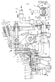
- a side pull mark 1 is shown on the right side of a feed table, not shown.
- a sheet to be aligned is transported approximately perpendicular to the plane 23 of the drawing against a front mark, not shown.
- the right edge of the sheet passes below a swab roller 3 which extends through a shell 2.
- the swab roller 3 is rotatably mounted on a swab roller lever 4 which can be pivoted about an axis 5.
- the pressure exerted by the swab roll 3 on a sheet to be aligned can be preset.
- a by means of an adjusting screw 7 Adaptation to the sheet thickness to be processed in each case shown adjustable shell 2.
- the contact pressure of the swab roller 3 can be varied by turning a threaded sleeve 19.
- a nut 20, which is rotatably arranged on the threaded sleeve 19, is counter-countered.
- a spring rod 18 is guided, on which the compression spring 6 is arranged.
- a curve 15 is fixed so that it rotates with the spindle 25.
- a roller 14 runs on the curved path of curve 15, which causes a swiveling movement of the swab roller lever 4 according to the curve shape about the axis 5 via a guide lever 16 when the spindle 25 rotates.
- the swab roll 3, which is supported in the swab roll lever on a head pin 21, is pressed in the same rhythm against an arc located between the shell 2 and the sliding plate 8.
- the spindle 25 also carries a further curve 22, which is connected to the curve 17 via a guide bush 17 and can be fastened to the sloted guide bush 17 by screws 27.
- the curve stroke and the length of the curve stroke of curve 22 define the control range for the drawing operation, which can be shifted by turning curve 22.
- a roller 11 runs in curve 22,
- the sliding plate 8 is fixed on the slide 29 by at least one fastening screw 9.
- the shape of the curve regions makes it possible to coordinate the time at which the swab roller 3 touches the sliding plate 8 with the pulling movement of the sliding plate 8, so that the sheet located with its right edge between the swab roller 3 and the sliding plate 8 can be pulled against a right stop 28.
- the setting of the curve 22 by twisting on the guide bushing 17 is facilitated by the use of a setting mark 26, the screws 27 connecting the curve 22 to the guide bushing 17 having to be loosened for the setting process.
- the sliding plate 8 has suction openings 30 which can be acted upon by suction air via a vacuum chamber 31. Air is sucked out of the vacuum chamber 31 via a connecting piece 32 and a flexible line 33.
- the flexible line 33 is connected to a control valve 34, with the aid of which the vacuum conducted via a line 35 can be timed.
- the strength of the vacuum can be adjusted by a pressure reducing device 36.
- the vacuum is generated via a suction line 37 with a vacuum source, not shown.
- At least one clock disk 38 is arranged on the spindle 25 or another single-turn shaft. By loosening the fastening screws 39 and 40, the clock disk 38 can be brought into the desired circumferential position and then fixed.
- the clock disc 38 has a circumferential direction extending recess between the control edges 41 and 42. This recess extends over the area during which the suction air is to take effect.
- a sensing element in the form of an electrical sensor switch 43 is shown schematically, which can be fixed at a suitable point on the system table.
- the switch 43 engages with its legs 44 and 45 the clock disc 38 and generates when the first control edge occurs, for. B. 41, until the appearance of the second control edge, for. B. 42, an electrical signal through which the suction air supply to the suction openings 30 in the slide plate 8 in the control valve 34 is released.
- the control valve 34 blocks the suction air supply to the suction openings 30. This blocking can be effected in a known manner by interrupting the supply path or by establishing a connection to the atmosphere, through which the vacuum breaks down.
- the vacuum supply via the control valve 34 to the suction openings 30 coincides with the initial pulling movement of the sliding plate 8 interacting with the swab roller 3, so that the sheet to be pulled against the stop 28 is accelerated very quickly, with the swab roller 3 the sheet in each case against the Suction openings 30 is pressed so that they can be completely covered and no incorrect air can arise.
- the force of the suction air exerted on the pressure carrier supports the pulling movement of the swab roller 3 and the sliding plate 8, so that despite the existing one relatively Great liability of the sheet at the beginning of the drawing process, which can be accelerated quickly.
- the vacuum is switched off again after the recess 41, 42 has overrun and the swab roller 3 and the sliding plate 8 pull the sheet to be aligned against the stop 28 with reduced tensile force As a result, the risk of upsetting and rebounding against the stop 28 is substantially reduced or eliminated. Due to the suction air support during the acceleration phase, it is possible to reduce the presettable pressure of the swab roller 3 against the sliding plate 8, so that in the last phase of the drawing process it is possible to switch to a sliding movement. This in turn prevents the arch from forming waves after it reaches the stop 28.
- the suction air can thus support the drawing movement at a specific time and for a specific duration.
- the intensity with which the suction air acts on the sheet to be aligned can be set by the pressure reducing device 36.
- control valve 34 can be controlled by means of an adjustable timer by means of electronic means when the recess is detected, ie when the first control edge occurs.
- a further clock disk 46 in this case, to be arranged next to the clock disc 38 on the spindle 25.
- the dimension of the recess extending in the circumferential direction can thus be changed by relative rotation between the clock disk 38 and the clock disk 46 shown in broken lines.
Abstract
Description
Die Erfindung betrifft eine Vorrichtung zum seitlichen Ausrichten von selbsttätig zugeführten Bogen an Druckmaschinen, insbesondere schnellaufenden Offsetmaschinen, bei welchen der Bogen durch eine an einem ortsfesten Ziehmarkengehäuse schwingend angeordnete Tupferrolle oder -segment auf eine in demselben hin-und herbewegte, als Ziehschuh dienende Schiebeplatte gedrückt und durch diese gegen den Anschlag der Seitenmarke ziehbar ist.The invention relates to a device for the lateral alignment of automatically supplied sheets on printing presses, in particular high-speed offset machines, in which the sheet is pressed by a swab roll or segment which is arranged in a swinging manner on a stationary drawing mark housing and is pressed back and forth on a sliding plate serving as a pulling shoe through this against the stop of the side mark is draggable.
Ziehmarken an Bogendruckmaschinen haben bekanntlich die Aufgabe, den vom Anleger einlaufenden Bogen seitlich exakt auszurichten. Diese Ausrichtung hat mit äußerster Präzision zu erfolgen, da durch Ausrichtdifferenzen Farbdifferenzen zwischen den Exemplaren auftreten können. Um eine optimale Ausrichtung zu erreichen, muß der Bogen deshalb exakt an einen Anschlag ziehbar sein, wobei ein Stauchen am Anschlag zu vermeiden ist. Daraus resultiert, daß die Ziehkraft differenziert auf die Größe des Bogens, seine Dicke, sein Gewicht und auf die von der Oberflächenbeschaffenheit abhängige Reibung einzustellen ist.Draw marks on sheet-fed printing machines are known to have the task of precisely aligning the sheet arriving from the feeder laterally. This alignment must be carried out with the utmost precision, since alignment differences can cause color differences between the specimens. In order to achieve an optimal alignment, the sheet must therefore be able to be pulled exactly against a stop, avoiding compression at the stop. The result of this is that the pulling force is differentiated according to the size of the sheet, its thickness, its weight and the friction depending on the surface condition.
Aus der DE-Patentschrift 1 015 009 ist bereits eine Vorrichtung zum seitlichen Ausrichten von selbsttätig zugeführten Bogen an Druckmaschinen bekannt, die rein mechanisch arbeitet, wobei eine Tupferrolle den Bogen auf einen quer zur Transportrichtung des Bogens hin-und herbewegbaren Schieber drückt. Dieser Schieber, auch Ziehblättchen genannt, kann z. B. entsprechend der erforderlichen Reibung mit verschiedenartiger Oberfläche, d. h. rauh, fein oder glatt, ausgeführt werden. Desweiteren kann gegebenenfalls bei dieser bekannten Vorrichtung durch Veränderung der Federvorspannung bzw. durch Austauschen einer Feder der Tupferrollenanpreßdruck auf die Schiebeplatte verändert werden. Insbesondere bei schnellaufenden Druckmaschinen steht für den Ausrichtvorgang nur eine sehr geringe Zeit zur Verfügung, weshalb hohe Beschleunigungswerte für die seitliche Bogenbewegung erforderlich sind. Während bei starken Druckträgern die Einstellung relativ unproblematisch ist, ist es bei dünnen Papieren schwierig, die Krafteinstellung der Ziehmarke und ihre Reibung so zu bemessen, daß einerseits der Druckträger die vorgegegebene Beschleunigung erfährt und andererseits nach dem Erreichen des Anschlags sofort in eine Rutschbewegung übergegangen wird, um ein Stauchen des Bogens zu vermeiden. Diese Schwierigkeit liegt vor allem auch darin, daß der auszurichtende Bogen aus dem Ruhezustand zu beschleunigen ist, weshalb eine möglichst hohe Anfangsbeschleunigung nötig wäre. Diese Zusammenhänge sind die Ursache, daß die bekannten Ziehmarken vor allem bei extrem hohem Bogendurchsatz pro Zeiteinheit nicht mit ausreichender Genauigkeit und Sicherheit arbeiten.A device for the lateral alignment of automatically supplied sheets on printing presses is already known from DE patent specification 1 015 009, which operates purely mechanically, a swab roller pressing the sheet onto a slide that can be moved back and forth transversely to the transport direction of the sheet. This slide, also called drawing paper, can, for. B. according to the required friction with different types of surface, d. H. rough, fine or smooth. Furthermore, the swab roller contact pressure on the sliding plate can optionally be changed in this known device by changing the spring preload or by exchanging a spring. In the case of high-speed printing machines in particular, there is only a very short time available for the alignment process, which is why high acceleration values are required for the lateral sheet movement. While the setting is relatively unproblematic with strong printing media, it is difficult with thin papers to measure the force setting of the drawing mark and its friction in such a way that on the one hand the printing media experiences the specified acceleration and, on the other hand, it immediately starts to slide after reaching the stop, to avoid crushing the bow. This difficulty lies primarily in the fact that the sheet to be aligned has to be accelerated from the idle state, which is why the highest possible initial acceleration would be necessary. These relationships are the cause that the known drawing marks do not work with sufficient accuracy and security, especially with extremely high sheet throughput per unit of time.
Die Aufgabe der Erfindung besteht deshalb in der Verbesserung der.eingangs definierten Vorrichtung zum seitlichen Ausrichten von selbsttätig zugeführten Bogen, um sowohl eine individuelle Krafteinstellung als auch eine hohe Anfangsbeschleunigung des auszurichtenden Bogens zu ermöglichen, wobei ein Austauschen von mechanischen Teilen nicht mehr erforderlich sein soll.The object of the invention is therefore to improve the initially defined device for Lateral alignment of automatically fed sheets in order to enable both an individual force setting and a high initial acceleration of the sheet to be aligned, wherein an exchange of mechanical parts should no longer be necessary.
Diese Aufgabe wird gemäß dem Kennzeichen des Patentanspruchs 1 gelöst. Vorteilhafte Weiterbildungen ergeben sich aus den Unteransprüchen und aus der Beschreibung in Verbindung mit der Zeichnung.This object is achieved according to the characterizing part of patent claim 1. Advantageous further developments result from the subclaims and from the description in conjunction with the drawing.
Aus der DE-Auslegeschrift 1 278 449 sind pneumatisch arbeitende Vorrichtungen zum seitlichen Ausrichten von Bogen an sich bekannt, bei denen mittels Saugschiebern, welche quer zur Bogenförderrichtung verschiebbar sind, die auszurichtenden Bogen gegen einen Anschlag gezogen werden. Bei derartigen Vorrichtungen wirkt jedoch die Saugluft während des gesamten Ausrichtvorganges und zwar kontinuierlich, so daß, ähnlich wie bei den rein mechanisch arbeitenden Vorrichtungen, der Beschleunigungsvorgang nicht zusätzlich unterstützt werden kann. Hinzu kommt, daß besonders bei dünnen Papieren die auszurichtenden Bogen die Saugdüsen nicht vollständig bedecken und bei starken Papieren mit glatter Oberfläche die für den Ausrichtvorgang erforderliche Zeit zu lang wird.From DE-Auslegeschrift 1 278 449 pneumatically operating devices for lateral alignment of sheets are known per se, in which the sheets to be aligned are pulled against a stop by means of suction slides which can be displaced transversely to the sheet conveying direction. In such devices, however, the suction air acts continuously throughout the alignment process, so that, similarly to the purely mechanical devices, the acceleration process cannot be additionally supported. In addition, the sheets to be aligned do not completely cover the suction nozzles, particularly in the case of thin papers, and the time required for the alignment process becomes too long in the case of strong papers with a smooth surface.
Bei der erfindungsgemäßen Vorrichtung hingegen ist durch die Tupferrolle gewährleistet, daß der auszurichtende Bogen jeweils auf die Saugöffnungen in der Schiebeplatte gedrückt wird und diese somit exakt verschließbar sind. Ein wesentlicher Vorteil der erfindungsgemäßen Vorrichtung liegt in der Möglichkeit, das den Beschleunigungsvorgang unterstützende Vakuum zeitlich definiert wirken zu lassen, so daß die im Bogenruhezustand verhältnismäßig große Haftreibung bzw. das Haftmoment schnell überwunden werden kann und daß durch rechtzeitiges Abschalten der Saugluft ein Stauchen des Bogens an dem Anschlag vermeidbar ist. Ebenso besteht die Möglichkeit, die Tupferrolle vor Erreichen des Anschlages zu heben. Die Vakuumunterstützung in der ersten Phase des Ziehvorganges ermöglicht zudem eine Reduzierung der mechanischen Einstellkräfte, wodurch zusätzlich die Gefahr der Bogenstauchung am Anschlag unterdrückt bzw. reduziert wird. Bei der erfindungsgemäßen Vorrichtung ist es nicht mehr erforderlich, die Anpreßkraft der Tupferrolle und die Rauhigkeit der Oberfläche der Schiebeplatte so feinfühlig aufeinander abzustimmen, da das Ende des Ziehvorganges mit wesentlich geringerer Zugkraft durchführbar ist.In the device according to the invention, on the other hand, the swab roller ensures that the sheet to be aligned is pressed onto the suction openings in the sliding plate and that these can thus be closed exactly. An essential advantage of the device according to the invention lies in the possibility of having the vacuum supporting the acceleration process act in a time-defined manner, so that the relatively high static friction or the moment of adhesion can be overcome quickly in the sheet resting state and that by timely switching off the suction air a compression of the sheet at the stop can be avoided. It is also possible to lift the swab roll before it reaches the stop. The vacuum support in the first phase of the pulling process also enables a reduction in the mechanical adjustment forces, which additionally suppresses or reduces the risk of bow compression at the stop. In the device according to the invention, it is no longer necessary to coordinate the contact pressure of the swab roller and the roughness of the surface of the sliding plate so sensitively, since the end of the drawing process can be carried out with a significantly lower tensile force.
Im folgenden wird die Erfindung anhand eines Ausführungsbeispiels im einzelnen beschrieben, wobei Bezug auf die beiliegende Zeichnung genommen wird.The invention is described in detail below using an exemplary embodiment, reference being made to the accompanying drawing.
In der Zeichnung ist eine an der rechten Seite eines nicht näher bezeichneten Anlegetisches angeordnete Seitenziehmarke 1 dargestellt. Ein auszurichtender Bogen wird etwa senkrecht zur Ebene 23 der Zeichnung gegen eine nicht gezeigte Vordermarke transportiert. Dabei gelangt die rechte Bogenkante unterhalb einer durch eine Muschel 2 greifende Tupferrolle 3. Die Tupferrolle 3 ist drehbar an einem Tupferrollenhebel 4 gelagert, der um eine Achse 5 schwenkbar ist.In the drawing, a side pull mark 1 is shown on the right side of a feed table, not shown. A sheet to be aligned is transported approximately perpendicular to the
Mittels einer Druckfeder 6 kann der von der Tupferrolle 3 aus einen auszurichtenden Bogen ausgeübte Andruck voreingestellt werden. über der Schiebeplatte 8 ist eine mittels einer Stellschraube 7 zur Anpassung an die jeweils zu bearbeitende Bogenstärke abstandsmäßig einstellbare Muschel 2 gezeigt. Der Auflagedruck der Tupferrolle 3 ist durch Drehen einer Gewindehülse 19 variierbar. Um diese Einstellung fixiert zu halten, wird eine Mutter 20, die auf der Gewindehülse 19 drehbar angeordnet ist, gegengekontert. In letzterer ist eine Federstange 18 geführt, auf der die Druckfeder 6 angeordnet ist.By means of a compression spring 6, the pressure exerted by the swab roll 3 on a sheet to be aligned can be preset. Above the sliding plate 8 is a by means of an adjusting screw 7 Adaptation to the sheet thickness to be processed in each case shown adjustable shell 2. The contact pressure of the swab roller 3 can be varied by turning a threaded
Auf der mit der Bogentransportvorrichtung synchronisierten Spindel 25 ist eine Kurve 15 fest aufgesetzt, so daß diese mit der Spindel 25 rotiert. An der Kurvenbahn der Kurve 15 läuft eine Rolle 14, die über einen Führungshebel 16 bei einer Rotation der Spindel 25 eine Schwenkbewegung des Tupferrollenhebels 4 entsprechend der Kurvenform um die Achse 5 verursacht. Dadurch wird im gleichen Rhythmus die Tupferrolle 3, die in dem Tupferrollenhebel auf einem Kopfbolzen 21 gelagert ist, gegen einen zwischen der Muschel 2 und der Schiebeplatte 8 befindlichen Bogen gepreßt.On the
Die Spindel 25 trägt außerdem eine weitere Kurve 22, die über eine Führungsbüchse 17 mit der Kurve 17 verbunden ist und durch Schrauben 27 an der mit Schlitzen versehenen Führungsbüchse 17 befestigt werden kann. Der Kurvenhub und die Länge des Kurvenhubes der Kurve 22 definieren den Steuerbereich für den Ziehbetrieb, der durch Verdrehen der Kurve 22 verlagert werden kann. In der Kurve 22 läuft eine Rolle 11,The
die mit einem Schieber 29 verbunden ist, so daß durch Drehen der Kurve eine im rechten Winkel zum Bogenlauf ausgeführte Links-Rechts-Verschiebung des auf Führungsrollen 12 und 24 geführten Schiebers 29 verursacht wird. Auf dem Schieber 29 ist durch mindestens eine Befestigungsschraube 9 die Schiebeplatte 8 fixiert.which is connected to a
Durch die Anordnung der verdrehbaren Kurven 15 und 22 auf einer gemeinsamen mit dem Bogentransport synchronisierten Spindel 25 ist durch die Formgebung der Kurvenbereiche eine Abstimmung des Zeitpunktes, zu dem die Tupferrolle 3 auf die Schiebeplatte 8 aufsetzt, mit der Ziehbewegung der Schiebeplatte 8 möglich, so daß der mit seiner rechten Kante zwischen der Tupferrolle 3 und der Schiebeplatte 8 befindliche Bogen gegen einen rechten Anschlag 28 ziehbar ist.Due to the arrangement of the
Die Einstellung der Kurve 22 durch Verdrehen auf der Führungsbüchse 17 wird durch die Verwendung einer Einstellmarke 26 erleichtert, wobei für den Einstellvorgang die die Kurve 22 mit der Führungsbüchse 17 verbindenden Schrauben 27 zu lösen sind.The setting of the
Die Schiebeplatte 8 weist Saugöffnungen 30 auf, die über eine Vakuumkammer 31 mit Saugluft beaufschlagbar sind. Aus der Vakuumkammer 31 wird über ein Anschlußstück 32 und eine flexible Leitung 33 Luft abgesaugt. Die flexible Leitung 33 steht mit einem Steuerventil 34 in Verbindung, mit dessen Hilfe das über eine Leitung 35 geführte Vakuum zeitlich steuerbar ist. Die Stärke des Vakuums ist durch eine Druckmindereinrichtung 36 einstellbar. Das Vakuum wird über eine Saugleitung 37 mit einer nicht dargestellten Vakuumquelle erzeugt.The sliding plate 8 has
Auf der Spindel 25 oder einer anderen Eintourenwelle ist mindestens eine Taktscheibe 38 angeordnet. Durch Lösen der Befestigungsschrauben 39 und 40 kann die Taktscheibe 38 in die gewünschte Umfangsposition gebracht und anschließend fixiert werden. Die Taktscheibe 38 weist eine sich in Umfangsrichtung erstreckende Ausnehmung zwischen den Steuerkanten 41 und 42 auf. Diese Ausnehmung erstreckt sich über den Bereich, während dessen die Saugluft wirksam werden soll.At least one
Über der Steuerscheibe 38 ist schematisch ein Abfühlelement in Form eines elektrischen Fühlschalters 43 dargestellt, der an einer geeigneten Stelle am Anlagetisch fixiert sein kann. Der Schalter 43 umgreift mit seinen Schenkeln 44 und 45 die Taktscheibe 38 und erzeugt beim Auftreten der ersten Steuerkante, z. B. 41, bis zum Auftreten der zweiten Steuerkante, z. B. 42, ein elektrisches Signal, durch das die Saugluftzuführung zu den Saugöffnungen 30 in der Schiebeplatte 8 im Steuerventil 34 freigegeben wird. Während der übrigen Zeit, d. h. während der restlichen Drehbewegung von etwa 330 , sperrt das Steuerventil 34 die Saugluftzuführung zu den Saugöffnungen 30. Diese Sperrung kann in bekannter Weise durch Unterbrechung des Zuführweges oder durch die Herstellung einer Verbindung zur Umgebung der Atmosphäre, durch die das Vakuum zusammenbricht, bewirkt werden.Above the
Die Vakuumzuführung über das Steuerventil 34 zu den Saugöffnungen 30 fällt zeitlich mit der Anfangsziehbewegung der mit der Tupferrolle 3 zusammenwirkenden Schiebeplatte 8 zusammen, so daß der gegen den Anschlag 28 zu ziehende Bogen sehr schnell beschleunigt wird, wobei durch die Tupferrolle 3 der Bogen jeweils gegen die Saugöffnungen 30 gedrückt wird, so daß diese vollständig abdeckbar sind und keine Fehlluft entstehen kann. In dieser Beschleunigungsphase unterstützt die auf den Druckträger ausgeübte Kraft der Saugluft die Ziehbewegung der Tupferrolle 3 und der Schiebeplatte 8, so daß trotz der bestehenden relativ großen Haftung des zu Beginn des Ziehvorgangs ruhenden Bogens dieser schnell beschleunigt werden kann.The vacuum supply via the
Nach der Beschleunigungsphase, die etwa ein Viertel der Zeit für den gesamten Ziehvorgang in Anspruch nehmen kann, wird das Vakuum nach Überlaufen der Ausnehmung 41, 42 wieder abgeschaltet und die Tupferrolle 3 und die Schiebeplatte 8 ziehen den auszurichtenden Bogen mit reduzierter Zugkraft gegen den Anschlag 28. Dadurch ist die Gefahr des Stauchens und Rückprallens am Anschlag 28 wesentlich reduziert bzw. eliminiert. Durch die Saugluftunterstützung während der Beschleunigungsphase ist es möglich, den voreinstellbaren Andruck der Tupferrolle 3 gegen die Schiebeplatte 8 zu reduzieren, so daß in der letzten Phase des Ziehvorganges in eine Rutschbewegung übergegangen werden kann. Dies wiederum verhindert die Wellenbildung des Bogens nach Erreichen des Anschlages 28.After the acceleration phase, which can take about a quarter of the time for the entire drawing process, the vacuum is switched off again after the
Mit Hilfe der Taktscheibe 38 kann somit zu einem bestimmten Zeitpunkt und für eine bestimmte Dauer die Saugluft während des Ziehvorganges die Ziehbewegung unterstützen. Die Intensität, mit der die Saugluft auf den auszurichtenden Bogen wirkt, ist durch die Druckmindereinrichtung 36 einstellbar.With the help of the
Falls eine individuelle Anpassung bzw. Veränderung der Wirkungsdauer der Saugluft während des Ziehvorganges gewünscht ist, kann mit Hilfe von elektronischen Mitteln beim Erfassen der Ausnehmung, d. h. beim Auftreten der ersten Steuerkante, durch ein einstellbares Zeitglied das Steuerventil 34 gesteuert werden. Das gleiche ist jedoch auch unter Verwendung einer weiteren Taktscheibe 46 möglich, die in diesem Fall neben der Taktscheibe 38 auf der Spindel 25 anzuordnen ist. Durch Relativverdrehung zwischen der Taktscheibe 38 und der gestrichelt dargestellten Taktscheibe 46 ist somit das Maß der sich in Umfangsrichtung erstreckenden Ausnehmung veränderbar. Somit ist eine individuelle Anpassung des Beginns der Saugluftzuführung zu den Saugöffnungen 30 an die Ziehbewegung der Tupferrolle 3 und der Schiebeplatte 8 sowie deren Dauer und Stärke möglich.If an individual adaptation or change of the duration of action of the suction air is desired during the drawing process, the
Claims (9)
Applications Claiming Priority (2)
| Application Number | Priority Date | Filing Date | Title |
|---|---|---|---|
| DE3011626 | 1980-03-26 | ||
| DE19803011626 DE3011626A1 (en) | 1980-03-26 | 1980-03-26 | DEVICE FOR SIDE ALIGNMENT OF SELF-FEEDING SHEETS ON PRINTING MACHINES |
Publications (2)
| Publication Number | Publication Date |
|---|---|
| EP0036496A1 true EP0036496A1 (en) | 1981-09-30 |
| EP0036496B1 EP0036496B1 (en) | 1984-05-09 |
Family
ID=6098353
Family Applications (1)
| Application Number | Title | Priority Date | Filing Date |
|---|---|---|---|
| EP81101332A Expired EP0036496B1 (en) | 1980-03-26 | 1981-02-25 | Device for the lateral adjustment of sheets automatically conveyed to printing machines |
Country Status (3)
| Country | Link |
|---|---|
| EP (1) | EP0036496B1 (en) |
| JP (1) | JPS56150552A (en) |
| DE (2) | DE3011626A1 (en) |
Cited By (2)
| Publication number | Priority date | Publication date | Assignee | Title |
|---|---|---|---|---|
| EP0161507A1 (en) * | 1984-05-12 | 1985-11-21 | Heidelberger Druckmaschinen Aktiengesellschaft | Feeder for sheet-processing machines, in particular printing machines |
| KR101138325B1 (en) * | 2004-10-06 | 2012-04-25 | 어시스트 메디칼 시스템즈, 인크. | Medical imaging system, dispensing system, and computer program product for assessing patient renal function prior to dispensing a contrast media as part of a medical imaging procedure |
Families Citing this family (7)
| Publication number | Priority date | Publication date | Assignee | Title |
|---|---|---|---|---|
| DE3219653C1 (en) * | 1982-05-26 | 1984-01-26 | Heidelberger Druckmaschinen Ag, 6900 Heidelberg | Device for checking the side sheet feeder and for interrupting the sheet feed in the event of a defective side sheet feeder |
| DE4118174C2 (en) * | 1991-06-03 | 2001-05-10 | Koenig & Bauer Ag | Device for the lateral alignment of sheets |
| DE4242731A1 (en) * | 1992-12-17 | 1994-06-23 | Heidelberger Druckmasch Ag | Device for the lateral alignment of sheets in printing machines |
| DE10010057B4 (en) * | 1999-03-19 | 2009-05-14 | Heidelberger Druckmaschinen Ag | Vacuum control for side puller |
| DE10233148A1 (en) | 2001-08-30 | 2003-03-20 | Heidelberger Druckmasch Ag | Sheet alignment device for a sheet processing machine, such as a printer, has an alignment mechanism with a progressive spring characteristic that is suitable for aligning papers of varying weights |
| JP4435554B2 (en) | 2003-12-17 | 2010-03-17 | リョービ株式会社 | Paper positioning device in a paper feeding section of a printing press |
| CN110271270B (en) * | 2019-07-11 | 2023-08-15 | 江苏华宇印涂设备集团有限公司 | Side gauge device of coating printer |
Citations (1)
| Publication number | Priority date | Publication date | Assignee | Title |
|---|---|---|---|---|
| DE2901188A1 (en) * | 1978-04-19 | 1979-10-31 | Polygraph Leipzig | Paper sheet aligner for printing machines - has front markers and sideways drawing device with holder acting against it |
-
1980
- 1980-03-26 DE DE19803011626 patent/DE3011626A1/en not_active Withdrawn
-
1981
- 1981-02-25 EP EP81101332A patent/EP0036496B1/en not_active Expired
- 1981-02-25 DE DE8181101332T patent/DE3163453D1/en not_active Expired
- 1981-03-26 JP JP4327681A patent/JPS56150552A/en active Granted
Patent Citations (1)
| Publication number | Priority date | Publication date | Assignee | Title |
|---|---|---|---|---|
| DE2901188A1 (en) * | 1978-04-19 | 1979-10-31 | Polygraph Leipzig | Paper sheet aligner for printing machines - has front markers and sideways drawing device with holder acting against it |
Cited By (2)
| Publication number | Priority date | Publication date | Assignee | Title |
|---|---|---|---|---|
| EP0161507A1 (en) * | 1984-05-12 | 1985-11-21 | Heidelberger Druckmaschinen Aktiengesellschaft | Feeder for sheet-processing machines, in particular printing machines |
| KR101138325B1 (en) * | 2004-10-06 | 2012-04-25 | 어시스트 메디칼 시스템즈, 인크. | Medical imaging system, dispensing system, and computer program product for assessing patient renal function prior to dispensing a contrast media as part of a medical imaging procedure |
Also Published As
| Publication number | Publication date |
|---|---|
| EP0036496B1 (en) | 1984-05-09 |
| JPS56150552A (en) | 1981-11-21 |
| JPH025652B2 (en) | 1990-02-05 |
| DE3163453D1 (en) | 1984-06-14 |
| DE3011626A1 (en) | 1981-10-01 |
Similar Documents
| Publication | Publication Date | Title |
|---|---|---|
| DE3215804C2 (en) | Sheet feed table for a sheet-fed rotary printing press | |
| EP1055622B2 (en) | Monitoring device for superimposed sheets | |
| DE4011286C2 (en) | ||
| EP0213397B1 (en) | Spring-mounted gripper for sheet-fed rotary printing machines | |
| EP0036496B1 (en) | Device for the lateral adjustment of sheets automatically conveyed to printing machines | |
| DE4340858A1 (en) | cylinder | |
| DE4230218C2 (en) | Pre-gripper of a sheet printing machine | |
| DE3731216C2 (en) | ||
| DE19804039A1 (en) | Suction gripper for transferring the rear edge of a sheet in a turning device of a sheet-fed rotary printing machine | |
| DE19962116A1 (en) | Guide device for guiding sheets and method for operating a guide device | |
| DE19643600C2 (en) | Influencing device overlaps sheets fed to a printing press | |
| EP0161507B1 (en) | Feeder for sheet-processing machines, in particular printing machines | |
| EP0679593B1 (en) | Intermittent roller for transporting sheets in a printing machine | |
| DE2127757B2 (en) | Missing sheet scanning and control device | |
| DE2836098A1 (en) | Offset printing press sheet insertion mechanism - has grips in cylinder trough interchangeable via slots in guide plate | |
| DE1786196A1 (en) | Method and device for setting paper sheets in printing machines | |
| DE10244219B4 (en) | Device and method for sheet supply to a sheet-processing machine, in particular printing machine | |
| DE2929583C2 (en) | Drag and drop marks | |
| EP0282828A1 (en) | Sheet smoother in the infeed area of a sheet processing machine | |
| EP1935817A2 (en) | Guide device for inserting sheets into a printing press | |
| DE4339388C2 (en) | Gripper control in turning drums | |
| DE10024018B4 (en) | Apparatus for forming a bow stream of scale-like partially overlapping sheets | |
| EP1334828B1 (en) | Device for laterally aligning sheets | |
| DE549538C (en) | Sheet feeding device for rotogravure printing presses for printing individual sheets | |
| DE4407505C2 (en) | Device for sheet alignment and separation on the top of a sheet stack |
Legal Events
| Date | Code | Title | Description |
|---|---|---|---|
| PUAI | Public reference made under article 153(3) epc to a published international application that has entered the european phase |
Free format text: ORIGINAL CODE: 0009012 |
|
| AK | Designated contracting states |
Designated state(s): CH DE FR GB IT |
|
| 17P | Request for examination filed |
Effective date: 19811014 |
|
| ITF | It: translation for a ep patent filed |
Owner name: BARZANO' E ZANARDO ROMA S.P.A. |
|
| GRAA | (expected) grant |
Free format text: ORIGINAL CODE: 0009210 |
|
| AK | Designated contracting states |
Designated state(s): CH DE FR GB IT LI |
|
| REF | Corresponds to: |
Ref document number: 3163453 Country of ref document: DE Date of ref document: 19840614 |
|
| ET | Fr: translation filed | ||
| PLBE | No opposition filed within time limit |
Free format text: ORIGINAL CODE: 0009261 |
|
| STAA | Information on the status of an ep patent application or granted ep patent |
Free format text: STATUS: NO OPPOSITION FILED WITHIN TIME LIMIT |
|
| 26N | No opposition filed | ||
| PG25 | Lapsed in a contracting state [announced via postgrant information from national office to epo] |
Ref country code: LI Effective date: 19860228 Ref country code: CH Effective date: 19860228 |
|
| REG | Reference to a national code |
Ref country code: CH Ref legal event code: PL |
|
| PGFP | Annual fee paid to national office [announced via postgrant information from national office to epo] |
Ref country code: FR Payment date: 19910116 Year of fee payment: 11 |
|
| PGFP | Annual fee paid to national office [announced via postgrant information from national office to epo] |
Ref country code: GB Payment date: 19910117 Year of fee payment: 11 Ref country code: DE Payment date: 19910117 Year of fee payment: 11 |
|
| ITTA | It: last paid annual fee | ||
| PG25 | Lapsed in a contracting state [announced via postgrant information from national office to epo] |
Ref country code: GB Effective date: 19920225 |
|
| GBPC | Gb: european patent ceased through non-payment of renewal fee | ||
| PG25 | Lapsed in a contracting state [announced via postgrant information from national office to epo] |
Ref country code: FR Effective date: 19921030 |
|
| PG25 | Lapsed in a contracting state [announced via postgrant information from national office to epo] |
Ref country code: DE Effective date: 19921103 |
|
| REG | Reference to a national code |
Ref country code: FR Ref legal event code: ST |