EP0036343B1 - Compresseur à recyclage par trompe pour séparation isotopique par diffusion gazeuse - Google Patents
Compresseur à recyclage par trompe pour séparation isotopique par diffusion gazeuse Download PDFInfo
- Publication number
- EP0036343B1 EP0036343B1 EP81400236A EP81400236A EP0036343B1 EP 0036343 B1 EP0036343 B1 EP 0036343B1 EP 81400236 A EP81400236 A EP 81400236A EP 81400236 A EP81400236 A EP 81400236A EP 0036343 B1 EP0036343 B1 EP 0036343B1
- Authority
- EP
- European Patent Office
- Prior art keywords
- compressor
- pressure
- diffuser
- flow
- main flow
- Prior art date
- Legal status (The legal status is an assumption and is not a legal conclusion. Google has not performed a legal analysis and makes no representation as to the accuracy of the status listed.)
- Expired
Links
- 238000009792 diffusion process Methods 0.000 title description 11
- 238000004064 recycling Methods 0.000 title description 10
- 238000005372 isotope separation Methods 0.000 title 1
- 230000006835 compression Effects 0.000 claims description 18
- 238000007906 compression Methods 0.000 claims description 18
- 230000006698 induction Effects 0.000 claims description 10
- 230000000694 effects Effects 0.000 claims description 5
- 239000002184 metal Substances 0.000 claims 6
- 239000000203 mixture Substances 0.000 description 9
- 238000009434 installation Methods 0.000 description 6
- 230000003068 static effect Effects 0.000 description 6
- 239000012530 fluid Substances 0.000 description 4
- 238000002347 injection Methods 0.000 description 4
- 239000007924 injection Substances 0.000 description 4
- 230000000155 isotopic effect Effects 0.000 description 4
- 241001344923 Aulorhynchidae Species 0.000 description 2
- 241001474791 Proboscis Species 0.000 description 2
- 230000004888 barrier function Effects 0.000 description 2
- 230000004907 flux Effects 0.000 description 2
- 238000012549 training Methods 0.000 description 2
- JFALSRSLKYAFGM-UHFFFAOYSA-N uranium(0) Chemical compound [U] JFALSRSLKYAFGM-UHFFFAOYSA-N 0.000 description 2
- JFALSRSLKYAFGM-OIOBTWANSA-N uranium-235 Chemical compound [235U] JFALSRSLKYAFGM-OIOBTWANSA-N 0.000 description 2
- 229910052770 Uranium Inorganic materials 0.000 description 1
- 238000005352 clarification Methods 0.000 description 1
- 238000004891 communication Methods 0.000 description 1
- 238000013461 design Methods 0.000 description 1
- 238000009826 distribution Methods 0.000 description 1
- 238000002474 experimental method Methods 0.000 description 1
- 239000008246 gaseous mixture Substances 0.000 description 1
- 230000010354 integration Effects 0.000 description 1
- 238000004519 manufacturing process Methods 0.000 description 1
- 238000000034 method Methods 0.000 description 1
- 238000005457 optimization Methods 0.000 description 1
- 239000000243 solution Substances 0.000 description 1
- 238000011144 upstream manufacturing Methods 0.000 description 1
- SANRKQGLYCLAFE-UHFFFAOYSA-H uranium hexafluoride Chemical compound F[U](F)(F)(F)(F)F SANRKQGLYCLAFE-UHFFFAOYSA-H 0.000 description 1
- 210000003462 vein Anatomy 0.000 description 1
Images

Classifications
-
- F—MECHANICAL ENGINEERING; LIGHTING; HEATING; WEAPONS; BLASTING
- F04—POSITIVE - DISPLACEMENT MACHINES FOR LIQUIDS; PUMPS FOR LIQUIDS OR ELASTIC FLUIDS
- F04D—NON-POSITIVE-DISPLACEMENT PUMPS
- F04D25/00—Pumping installations or systems
- F04D25/16—Combinations of two or more pumps ; Producing two or more separate gas flows
Definitions
- the present invention relates to a compressor with recycling of a secondary flow.
- the present invention relates to a compressor which makes it possible to deliver in its diffuser an output flow at a given pressure from a main flow having a first pressure and a secondary flow at a second pressure, said second pressure being greater than said first pressure, said outlet pressure being greater than said first and second pressures.
- the present invention relates to a compressor of this type for installations for enriching uranium by the gas diffusion process. It is known that in such installations, the enrichment of the gaseous mixture containing the isotopic mixture of uranium 235 and uranium 238 takes place through a cascade of diffusers in which the uranium hexafluoride circulates. In each diffusion stage, that is to say in each diffuser, it is necessary to inject on the one hand the gas flow leaving the preceding stage and on the other hand recycling the secondary gas flow coming from the following stage.
- FIG. 1 shows the stages N - 1, N and N + 1 of isotopic enrichment by gas diffusion.
- the gas containing the isotopic mixture is introduced into a set of porous diffusion or diffusing barriers and a fraction of this gas flow crosses the porous wall to enrich in the lighter isotope, that is to say the uranium 235.
- This flow which has passed through the porous wall in the diffuser of rank N is recycled at the inlet of the diffuser N + 1.
- the flow which has not diffused in the diffuser N is recycled in an upstream diffuser whose rank is a function of the enrichment rate.
- the main gas stream which has diffused in the row N diffuser is recycled via a compressor in the row N + 1 diffuser.
- the gas stream which has not diffused is recycled in the diffuser of rank N - 1.
- the diffusers D N - 1 , D N , D N + 1 are symbolized with a barrier S N - 1 ' B N , B N + 1 and the compressors C N - 1 , CN and C N + 1 .
- the arrows represent the different recycling of broadcast and non-broadcast streams.
- the compressor comprises a main compression assembly which processes the main flow and an auxiliary compression wheel which compresses the flow to be recycled so that the assembly of the outlet flow has the same pressure in a so-called mixing stage.
- the design of this stage is complex from an aerodynamic point of view and its realization is expensive.
- a compressor according to the preamble of claim 1 which allows the recycling of a secondary gas flow.
- This compressor comprises a main compressor which compresses the main flow to an intermediate pressure which is the inlet pressure of the secondary flow and which then carries, by means of a helical wheel and a diffuser comprising a fixed vane, two streams, after mixing, at the outlet pressure which is higher than said intermediate pressure.
- the object of the present invention is therefore to produce a compressor which does not include this auxiliary wheel but which nevertheless makes it possible to ensure the compression of the secondary gas flow and the mixture of the main flow and the secondary flow to obtain an output flow at a adequate pressure.
- Another object of the invention is to provide such a compressor allowing such recycling so that its manufacture is of reduced cost.
- a second object of the present invention is to provide a compressor allowing said recycling using devices integrated in the compressor, these devices being static.
- a third object of the invention is to provide such a compressor in the case where the pressure ratio required for the secondary or recycled flow is low, that is to say slightly greater than 1. This ratio is for example between 1.01 and 1.05.
- the invention relates to a compressor for delivering in its diffuser an output flow at a given pressure from a main flow at a first pressure and a secondary flow at a second pressure, said second pressure being greater than said first pressure, said outlet pressure being greater than said first and second pressures, said compressor comprising an inlet of the main flow, mobile compression means for raising the pressure of the main flow and static means housed in said diffuser, which is characterized in that the pressure of the main flow is raised by the mobile compression means to a value greater than said outlet pressure, the static means forming an induction nozzle with proboscis effect, traversed by said main flow and receiving, downstream of said nozzle said secondary flow which is thus entrained and recompressed by said main flow.
- static means forming an induction nozzle are used to mix and bring said mixture of flow to the appropriate pressure, in order to '' obtain an output flow at the desired pressure.
- static devices forming a trunk are used in the compressor diffuser to produce, using an induction nozzle, a mixture of the two gaseous flows, so that they exit at a suitable pressure.
- the integration of this injector or induction system is carried out in such a way that the best possible overall efficiency for the compressor is obtained whatever the type of original compressor.
- the invention therefore relates to axial compressors with toroidal diffuser and axial compressors with straight diffuser.
- the compressor diffuser there is integrated into the compressor diffuser a system forming an injection tube or induction nozzle in which the main flow constitutes the drive flow of the secondary flow, the total pressure to which the main flow is carried being slightly higher. at the final pressure for the mixture that one wishes to obtain, but the static pressure at the junction of the two flows is common.
- the calculations and experiments carried out show that an optimization of the system is thus obtained if the pressure ratio of the recycled secondary flow is of the order of 1.05.
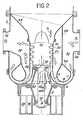
- FIG 2 there is shown a first embodiment of the invention in the case of an axial compressor with toroidal diffuser.
- the housing of the compressor consists of a cylindrical shell 2 closed at its bottom by a base part 4.
- a biconical housing 6 On this base part 4 is fixed a biconical housing 6 the ends of which are mounted bearings 8 and 10.
- the shaft 12 of the compressor at the end of which there is the rotor 14 with its blades of blades 16.
- the rotor 18 of the drive motor linked to the shaft 12 and the stator 20 of this motor which is integral with the bottom part 4.
- stator of the compressor which is constituted by a cylindrical sheet 22 inside which blades 25 have been mounted which cooperate with the rings of movable blades 16 of the rotor.
- This mobile assembly therefore constitutes the means for compressing the fluid.
- the sheet 22 of the stator extends a convergent 24 connected by its upper periphery to the shell 2 of the compressor housing.
- the convergent 24 constitutes the inlet of the main gas stream to be compressed and at the outlet 26 of the space limited by the stator 22, the main stream is compressed.
- stator 22 and the cylindrical shell 2 there are several separating sheets.
- the substantially cylindrical sheet 28 which has an inlet space 30 connected to the nozzle 32 through which enters the secondary fluid, that is to say the gas flow to be recycled.
- a second separating plate 34 which defines with the bottom part 4 the toric diffuser of the compressor. It can therefore be seen that the lower part of the space 30 can communicate with the lower zone 26 defined by the stator 22.
- the space 36 connected to the diffusion zone, this space being provided with the outlet nozzle 38 for the outlet gas stream which is constituted by the mixture of main stream entering through the convergent 24 after compression and of the stream to be recycled entering through the nozzle 32.
- these nozzles are placed at the inlet of the compressor diffuser. More precisely, as can be seen in FIG. 2, these nozzles consist of a sheet 40 which extends the stator 22 of the compressor. This sheet is corrugated and comprises a succession of hollows 40a and steps 40b. We also see that this sheet 40 is disposed between the bottom part 4 and the separating sheet 34. It is therefore understood that in this way the recesses 40a are in communication with the zone 26 of the outlet of the own compressor ment said and the steps 40b with the space 30 for admitting the secondary flow to be recycled.
- the hollows 40a form convergent passages which, with the steps 40b, constitute the equivalent of an induction nozzle with proboscis effect.
- the interpenetration zone A corresponding to the zone of the sheet 40, the mixing zone B and finally the diffusion zone C proper.
- the operation of the compressor with recycling according to the invention follows clearly from the preceding description.
- the main flow F 1 enters through the convergent 24 and is compressed from a pressure P 1 to a pressure slightly higher than the desired outlet pressure P 3 .
- the secondary flow F 2 at the pressure P 2 is admitted by the nozzle 32 and enters the space 30.
- This flow mixes in zone B and arrives in the diffusion zone C from where it enters space 36.
- a mixed flow F 3 is therefore obtained at the desired pressure P 3 .
- the compression ratio provided by the rotor 14 is slightly higher than the pressure that we want to obtain at output P 3 .
- This excess energy is used as the driving fluid in the injection tube or nozzle.
- This device is particularly advantageous when the compression ratio required for the recycled secondary fluid is low around the value 1.05.
- FIG. 3 a second embodiment of the compressor of the axial type is shown.
- the bottom part 4 is traversed by the shaft 12" of the rotor 14 "of the compressor, the rotor being of course provided with its blast rings.
- the rotor 14" is surrounded by its stator constituted by the ferrule 22 "and 25 "fixed blades.
- a separating sheet 34 of revolution is connected by an O-ring bottom 34 "a to the lower part of the shell 22" of the stator of the compressor.
- the upper end of the separating sheet 34 is connected to the lower end of an outlet divergent 60 through which the mixed flow F 3 exits.
- the separating sheet 34" firstly defines with the ferrule 22 "a space internal 62 and on the other hand, with the external casing 2 "an external space 64.
- a nozzle 66 opening into the casing 2" allows the introduction of the main flow F i .
- a portion of pipe 68 passes through the casing 2 "and is connected to the separating plate 34 ".
- the pipe 68 crosses in a sealed manner the external space 64 and opens into the internal space 62. It therefore allows the introduction of the flow to be recycled F 2 into the space 62.
- the ferrule 22 "of the compressor stator is extended by a corrugated sheet 40" similar to the corrugated sheet 40 shown in FIG. 2.
- This sheet 40 “thus defines two series of passages 40" a and 40 "b alternating and regularly distributed around the axis of the compressor. The definition of these passages is completed on the one hand by the lower part of the divergent 60 and on the other hand by the extension 70 of the rotor 14 ". These two types of passage open at their upper end into the divergent 60. At their end lower, the passages 40 "a open into the compression zone internal to the shell 22" and the passages 40 "b into the internal space 62. A plurality of inductor nozzles according to the invention are thus produced.
- the advantage of the invention is all the greater when the compression ratio of the recycled stream is lower. Likewise, this advantage is all the greater when the flow rate to be recycled is lower compared to the flow rate of the main flow.
Landscapes
- Engineering & Computer Science (AREA)
- Mechanical Engineering (AREA)
- General Engineering & Computer Science (AREA)
- Structures Of Non-Positive Displacement Pumps (AREA)
- Jet Pumps And Other Pumps (AREA)
Applications Claiming Priority (2)
| Application Number | Priority Date | Filing Date | Title |
|---|---|---|---|
| FR8004998 | 1980-03-06 | ||
| FR8004998A FR2477646A1 (fr) | 1980-03-06 | 1980-03-06 | Compresseur a recyclage par trompe pour separation isotopique par diffusion gazeuse |
Publications (2)
| Publication Number | Publication Date |
|---|---|
| EP0036343A1 EP0036343A1 (fr) | 1981-09-23 |
| EP0036343B1 true EP0036343B1 (fr) | 1985-04-24 |
Family
ID=9239366
Family Applications (1)
| Application Number | Title | Priority Date | Filing Date |
|---|---|---|---|
| EP81400236A Expired EP0036343B1 (fr) | 1980-03-06 | 1981-02-17 | Compresseur à recyclage par trompe pour séparation isotopique par diffusion gazeuse |
Country Status (5)
| Country | Link |
|---|---|
| US (1) | US4431377A (cg-RX-API-DMAC10.html) |
| EP (1) | EP0036343B1 (cg-RX-API-DMAC10.html) |
| JP (1) | JPS5718500A (cg-RX-API-DMAC10.html) |
| DE (1) | DE3170088D1 (cg-RX-API-DMAC10.html) |
| FR (1) | FR2477646A1 (cg-RX-API-DMAC10.html) |
Families Citing this family (2)
| Publication number | Priority date | Publication date | Assignee | Title |
|---|---|---|---|---|
| DE3443672A1 (de) * | 1984-11-30 | 1986-06-05 | C. Gerhardt Fabrik Und Lager Chemischer Apparate Gmbh & Co Kg, 5300 Bonn | Saugstrahlpumpe zum evakuieren und absaugen von aggressiven medien, mit wasserstrahlpumpen, ohne druckwasserbetrieb |
| JPH06100684B2 (ja) * | 1986-04-26 | 1994-12-12 | 共同印刷株式会社 | カラーフィルタの製造方法 |
Citations (4)
| Publication number | Priority date | Publication date | Assignee | Title |
|---|---|---|---|---|
| FR923774A (fr) * | 1943-11-05 | 1947-07-17 | Power Jets Res & Dev Ltd | Perfectionnements apportés aux mélangeurs de fluides |
| FR2278958A1 (fr) * | 1974-06-28 | 1976-02-13 | Commissariat Energie Atomique | Groupe moto-compresseur, notamment pour gaz dangereux |
| FR2338400A1 (fr) * | 1976-01-13 | 1977-08-12 | Applic Ventilation | Sur-exhausteur statique |
| US4117671A (en) * | 1976-12-30 | 1978-10-03 | The Boeing Company | Noise suppressing exhaust mixer assembly for ducted-fan, turbojet engine |
Family Cites Families (7)
| Publication number | Priority date | Publication date | Assignee | Title |
|---|---|---|---|---|
| DE280420C (cg-RX-API-DMAC10.html) * | ||||
| FR396547A (fr) * | 1908-11-20 | 1909-04-14 | Clemens Kiesselbach | Injecteur à gaz ou à liquides combiné avec une pompe rotative |
| US1115942A (en) * | 1913-07-21 | 1914-11-03 | Gen Electric | Centrifugal pump and air-compressor. |
| FR1237157A (fr) * | 1959-05-26 | 1960-07-29 | Hispano Suiza Sa | Perfectionnements apportés aux installations à compresseur pour flux gazeux devant être partiellement recyclé |
| US3625820A (en) * | 1968-06-14 | 1971-12-07 | Gen Electric | Jet pump in a boiling water-type nuclear reactor |
| FR2359629A1 (fr) * | 1976-07-29 | 1978-02-24 | Snecma | Perfectionnement aux installations d'enrichissement isotopique par diffusion gazeuse selective equipees de moto-compresseurs |
| JPS5587887A (en) * | 1978-12-26 | 1980-07-03 | Kazunori Minami | Aerator |
-
1980
- 1980-03-06 FR FR8004998A patent/FR2477646A1/fr active Granted
-
1981
- 1981-02-17 DE DE8181400236T patent/DE3170088D1/de not_active Expired
- 1981-02-17 EP EP81400236A patent/EP0036343B1/fr not_active Expired
- 1981-03-04 JP JP3108181A patent/JPS5718500A/ja active Granted
- 1981-03-05 US US06/240,936 patent/US4431377A/en not_active Expired - Fee Related
Patent Citations (4)
| Publication number | Priority date | Publication date | Assignee | Title |
|---|---|---|---|---|
| FR923774A (fr) * | 1943-11-05 | 1947-07-17 | Power Jets Res & Dev Ltd | Perfectionnements apportés aux mélangeurs de fluides |
| FR2278958A1 (fr) * | 1974-06-28 | 1976-02-13 | Commissariat Energie Atomique | Groupe moto-compresseur, notamment pour gaz dangereux |
| FR2338400A1 (fr) * | 1976-01-13 | 1977-08-12 | Applic Ventilation | Sur-exhausteur statique |
| US4117671A (en) * | 1976-12-30 | 1978-10-03 | The Boeing Company | Noise suppressing exhaust mixer assembly for ducted-fan, turbojet engine |
Also Published As
| Publication number | Publication date |
|---|---|
| JPS6321040B2 (cg-RX-API-DMAC10.html) | 1988-05-02 |
| FR2477646A1 (fr) | 1981-09-11 |
| DE3170088D1 (en) | 1985-05-30 |
| EP0036343A1 (fr) | 1981-09-23 |
| FR2477646B1 (cg-RX-API-DMAC10.html) | 1984-07-20 |
| US4431377A (en) | 1984-02-14 |
| JPS5718500A (en) | 1982-01-30 |
Similar Documents
| Publication | Publication Date | Title |
|---|---|---|
| EP0781929B1 (fr) | Dispositif de pompage ou de compression d'un fluide polyphasique à aubage en tandem | |
| FR2556054A1 (fr) | Diffuseur pour compresseur centrifuge | |
| EP0224514B1 (fr) | Groupe generateur hydro-electrique portatif | |
| EP0506516B1 (fr) | Chambre de combustion de turbomachine comportant un réglage du débit de comburant | |
| FR2772083A1 (fr) | Module a pompe pour reservoir de carburant d'un vehicule | |
| CA2047975C (fr) | Dispositif de pompage ou de compression polyphasique et son utilisation | |
| FR2722536A1 (fr) | Pompe de carburant a deux etages | |
| EP0036343B1 (fr) | Compresseur à recyclage par trompe pour séparation isotopique par diffusion gazeuse | |
| EP1746348B1 (fr) | Turbomachine à distribution angulaire de l'air | |
| FR2843040A1 (fr) | Extracteur centrifuge | |
| BE1000524A4 (fr) | Procede et dispositif de separation aerodynamique de composants d'un courant gazeux. | |
| EP0359682B1 (fr) | Dispositif pour la séparation sélective de particules dans un liquide, notamment pour l'épuration de suspensions fibreuses papetières | |
| FR2670539A1 (fr) | Pompe multi-etagee destinee particulierement au pompage d'un fluide multiphasique. | |
| CA2320927C (fr) | Cellule de pompage d'un effluent polyphasique et pompe comportant au moins une de ces cellules | |
| FR2750455A1 (fr) | Tete d'injection pour des moteurs-fusees | |
| EP0253689B1 (fr) | Ejecteur à rotation induite | |
| FR2536460A1 (fr) | Diffuseur compact perfectionne, convenant particulierement pour des turbines a gaz de haute puissance | |
| FR2794817A1 (fr) | Compresseur radial avec fenetes en paroi | |
| CH127029A (fr) | Epurateur pour fluides gazeux chargés d'impuretés en suspension. | |
| FR2960923A1 (fr) | Controle de la poussee axiale par guidage de l'air preleve sur un compresseur centrifuge | |
| EP0026017A1 (fr) | Réducteur à pression à deux étages pour moteurs à gaz liquéfié équipés d'un système de démarrage automatique | |
| CA2351677A1 (fr) | Pompe a vide | |
| FR2525692A1 (fr) | Injecteur de carburant pour moteurs a turbine a gaz | |
| FR2574871A1 (fr) | Compresseur centrifuge diphasique | |
| FR2913068A1 (fr) | Cartouche pour l'optimisation de la consommation en carburant d'un moteur a explosion et procede associe. |
Legal Events
| Date | Code | Title | Description |
|---|---|---|---|
| PUAI | Public reference made under article 153(3) epc to a published international application that has entered the european phase |
Free format text: ORIGINAL CODE: 0009012 |
|
| 17P | Request for examination filed |
Effective date: 19810226 |
|
| AK | Designated contracting states |
Designated state(s): CH DE FR GB IT |
|
| ITF | It: translation for a ep patent filed | ||
| GRAA | (expected) grant |
Free format text: ORIGINAL CODE: 0009210 |
|
| AK | Designated contracting states |
Designated state(s): CH DE FR GB IT LI |
|
| REF | Corresponds to: |
Ref document number: 3170088 Country of ref document: DE Date of ref document: 19850530 |
|
| PLBE | No opposition filed within time limit |
Free format text: ORIGINAL CODE: 0009261 |
|
| STAA | Information on the status of an ep patent application or granted ep patent |
Free format text: STATUS: NO OPPOSITION FILED WITHIN TIME LIMIT |
|
| 26N | No opposition filed | ||
| PGFP | Annual fee paid to national office [announced via postgrant information from national office to epo] |
Ref country code: FR Payment date: 19910128 Year of fee payment: 11 |
|
| PGFP | Annual fee paid to national office [announced via postgrant information from national office to epo] |
Ref country code: GB Payment date: 19910205 Year of fee payment: 11 Ref country code: CH Payment date: 19910205 Year of fee payment: 11 |
|
| ITTA | It: last paid annual fee | ||
| PGFP | Annual fee paid to national office [announced via postgrant information from national office to epo] |
Ref country code: DE Payment date: 19910430 Year of fee payment: 11 |
|
| PG25 | Lapsed in a contracting state [announced via postgrant information from national office to epo] |
Ref country code: GB Effective date: 19920217 |
|
| PG25 | Lapsed in a contracting state [announced via postgrant information from national office to epo] |
Ref country code: LI Effective date: 19920229 Ref country code: CH Effective date: 19920229 |
|
| GBPC | Gb: european patent ceased through non-payment of renewal fee | ||
| PG25 | Lapsed in a contracting state [announced via postgrant information from national office to epo] |
Ref country code: FR Effective date: 19921030 |
|
| REG | Reference to a national code |
Ref country code: CH Ref legal event code: PL |
|
| PG25 | Lapsed in a contracting state [announced via postgrant information from national office to epo] |
Ref country code: DE Effective date: 19921103 |
|
| REG | Reference to a national code |
Ref country code: FR Ref legal event code: ST |