EP0035796B1 - Thermoplastic synthetic filaments and process for producing the same - Google Patents
Thermoplastic synthetic filaments and process for producing the same Download PDFInfo
- Publication number
- EP0035796B1 EP0035796B1 EP81101790A EP81101790A EP0035796B1 EP 0035796 B1 EP0035796 B1 EP 0035796B1 EP 81101790 A EP81101790 A EP 81101790A EP 81101790 A EP81101790 A EP 81101790A EP 0035796 B1 EP0035796 B1 EP 0035796B1
- Authority
- EP
- European Patent Office
- Prior art keywords
- filament
- filaments
- polymer
- dispersed
- weight
- Prior art date
- Legal status (The legal status is an assumption and is not a legal conclusion. Google has not performed a legal analysis and makes no representation as to the accuracy of the status listed.)
- Expired
Links
- 238000000034 method Methods 0.000 title claims description 52
- 229920001169 thermoplastic Polymers 0.000 title claims description 26
- 230000008569 process Effects 0.000 title claims description 25
- 239000004416 thermosoftening plastic Substances 0.000 title claims description 24
- 229920000642 polymer Polymers 0.000 claims description 120
- 239000011159 matrix material Substances 0.000 claims description 56
- 230000002093 peripheral effect Effects 0.000 claims description 34
- 239000003513 alkali Substances 0.000 claims description 29
- 239000000203 mixture Substances 0.000 claims description 26
- 229920000728 polyester Polymers 0.000 claims description 22
- 238000009987 spinning Methods 0.000 claims description 21
- 229920002492 poly(sulfone) Polymers 0.000 claims description 13
- 230000009477 glass transition Effects 0.000 claims description 7
- 238000006116 polymerization reaction Methods 0.000 claims description 7
- 239000000178 monomer Substances 0.000 claims description 4
- 239000010419 fine particle Substances 0.000 claims description 3
- 238000011084 recovery Methods 0.000 claims description 2
- MMINFSMURORWKH-UHFFFAOYSA-N 3,6-dioxabicyclo[6.2.2]dodeca-1(10),8,11-triene-2,7-dione Chemical group O=C1OCCOC(=O)C2=CC=C1C=C2 MMINFSMURORWKH-UHFFFAOYSA-N 0.000 claims 2
- 230000000052 comparative effect Effects 0.000 description 34
- 239000004744 fabric Substances 0.000 description 19
- GWEVSGVZZGPLCZ-UHFFFAOYSA-N Titan oxide Chemical compound O=[Ti]=O GWEVSGVZZGPLCZ-UHFFFAOYSA-N 0.000 description 16
- HEMHJVSKTPXQMS-UHFFFAOYSA-M Sodium hydroxide Chemical compound [OH-].[Na+] HEMHJVSKTPXQMS-UHFFFAOYSA-M 0.000 description 12
- -1 for example Substances 0.000 description 10
- 239000004408 titanium dioxide Substances 0.000 description 8
- KWYUFKZDYYNOTN-UHFFFAOYSA-M Potassium hydroxide Chemical compound [OH-].[K+] KWYUFKZDYYNOTN-UHFFFAOYSA-M 0.000 description 6
- KKEYFWRCBNTPAC-UHFFFAOYSA-N Terephthalic acid Chemical compound OC(=O)C1=CC=C(C(O)=O)C=C1 KKEYFWRCBNTPAC-UHFFFAOYSA-N 0.000 description 6
- 229920000139 polyethylene terephthalate Polymers 0.000 description 6
- 239000005020 polyethylene terephthalate Substances 0.000 description 6
- 239000007864 aqueous solution Substances 0.000 description 5
- 230000015572 biosynthetic process Effects 0.000 description 5
- 239000003795 chemical substances by application Substances 0.000 description 5
- 150000001875 compounds Chemical class 0.000 description 5
- LYCAIKOWRPUZTN-UHFFFAOYSA-N ethylene glycol Natural products OCCO LYCAIKOWRPUZTN-UHFFFAOYSA-N 0.000 description 5
- 239000000835 fiber Substances 0.000 description 5
- 239000010954 inorganic particle Substances 0.000 description 5
- 230000001788 irregular Effects 0.000 description 5
- 238000004804 winding Methods 0.000 description 5
- 238000010521 absorption reaction Methods 0.000 description 4
- 238000001816 cooling Methods 0.000 description 4
- 238000010438 heat treatment Methods 0.000 description 4
- 239000002245 particle Substances 0.000 description 4
- XLYOFNOQVPJJNP-UHFFFAOYSA-N water Substances O XLYOFNOQVPJJNP-UHFFFAOYSA-N 0.000 description 4
- DNIAPMSPPWPWGF-UHFFFAOYSA-N Propylene glycol Chemical compound CC(O)CO DNIAPMSPPWPWGF-UHFFFAOYSA-N 0.000 description 3
- 238000007664 blowing Methods 0.000 description 3
- 238000004043 dyeing Methods 0.000 description 3
- 238000002074 melt spinning Methods 0.000 description 3
- 239000000243 solution Substances 0.000 description 3
- 239000004952 Polyamide Substances 0.000 description 2
- 239000004793 Polystyrene Substances 0.000 description 2
- CDBYLPFSWZWCQE-UHFFFAOYSA-L Sodium Carbonate Chemical compound [Na+].[Na+].[O-]C([O-])=O CDBYLPFSWZWCQE-UHFFFAOYSA-L 0.000 description 2
- 206010061592 cardiac fibrillation Diseases 0.000 description 2
- 230000003247 decreasing effect Effects 0.000 description 2
- 238000001125 extrusion Methods 0.000 description 2
- 230000002600 fibrillogenic effect Effects 0.000 description 2
- WGCNASOHLSPBMP-UHFFFAOYSA-N hydroxyacetaldehyde Natural products OCC=O WGCNASOHLSPBMP-UHFFFAOYSA-N 0.000 description 2
- 238000009940 knitting Methods 0.000 description 2
- 230000003287 optical effect Effects 0.000 description 2
- 229920002647 polyamide Polymers 0.000 description 2
- 238000006068 polycondensation reaction Methods 0.000 description 2
- 229920000098 polyolefin Polymers 0.000 description 2
- 229920002223 polystyrene Polymers 0.000 description 2
- BWHMMNNQKKPAPP-UHFFFAOYSA-L potassium carbonate Chemical compound [K+].[K+].[O-]C([O-])=O BWHMMNNQKKPAPP-UHFFFAOYSA-L 0.000 description 2
- WGTYBPLFGIVFAS-UHFFFAOYSA-M tetramethylammonium hydroxide Chemical compound [OH-].C[N+](C)(C)C WGTYBPLFGIVFAS-UHFFFAOYSA-M 0.000 description 2
- 238000009941 weaving Methods 0.000 description 2
- PUPZLCDOIYMWBV-UHFFFAOYSA-N (+/-)-1,3-Butanediol Chemical compound CC(O)CCO PUPZLCDOIYMWBV-UHFFFAOYSA-N 0.000 description 1
- RNFJDJUURJAICM-UHFFFAOYSA-N 2,2,4,4,6,6-hexaphenoxy-1,3,5-triaza-2$l^{5},4$l^{5},6$l^{5}-triphosphacyclohexa-1,3,5-triene Chemical compound N=1P(OC=2C=CC=CC=2)(OC=2C=CC=CC=2)=NP(OC=2C=CC=CC=2)(OC=2C=CC=CC=2)=NP=1(OC=1C=CC=CC=1)OC1=CC=CC=C1 RNFJDJUURJAICM-UHFFFAOYSA-N 0.000 description 1
- ISPYQTSUDJAMAB-UHFFFAOYSA-N 2-chlorophenol Chemical compound OC1=CC=CC=C1Cl ISPYQTSUDJAMAB-UHFFFAOYSA-N 0.000 description 1
- 241001589086 Bellapiscis medius Species 0.000 description 1
- 229920001634 Copolyester Polymers 0.000 description 1
- 238000005299 abrasion Methods 0.000 description 1
- 239000000654 additive Substances 0.000 description 1
- 125000002947 alkylene group Chemical group 0.000 description 1
- 239000002216 antistatic agent Substances 0.000 description 1
- 230000008901 benefit Effects 0.000 description 1
- 238000009835 boiling Methods 0.000 description 1
- 238000005282 brightening Methods 0.000 description 1
- 239000003054 catalyst Substances 0.000 description 1
- 230000008859 change Effects 0.000 description 1
- 238000004040 coloring Methods 0.000 description 1
- 238000002050 diffraction method Methods 0.000 description 1
- 238000000578 dry spinning Methods 0.000 description 1
- 230000002708 enhancing effect Effects 0.000 description 1
- 238000005886 esterification reaction Methods 0.000 description 1
- 239000003063 flame retardant Substances 0.000 description 1
- NLYAJNPCOHFWQQ-UHFFFAOYSA-N kaolin Chemical compound O.O.O=[Al]O[Si](=O)O[Si](=O)O[Al]=O NLYAJNPCOHFWQQ-UHFFFAOYSA-N 0.000 description 1
- 239000000463 material Substances 0.000 description 1
- 238000002844 melting Methods 0.000 description 1
- 230000008018 melting Effects 0.000 description 1
- 229910052751 metal Inorganic materials 0.000 description 1
- 239000002184 metal Substances 0.000 description 1
- 238000002156 mixing Methods 0.000 description 1
- 229920001707 polybutylene terephthalate Polymers 0.000 description 1
- 229910000027 potassium carbonate Inorganic materials 0.000 description 1
- 238000002360 preparation method Methods 0.000 description 1
- 230000009467 reduction Effects 0.000 description 1
- 229910000029 sodium carbonate Inorganic materials 0.000 description 1
- 239000007787 solid Substances 0.000 description 1
- 239000003381 stabilizer Substances 0.000 description 1
- 239000007858 starting material Substances 0.000 description 1
- 239000000126 substance Substances 0.000 description 1
- 238000002166 wet spinning Methods 0.000 description 1
Images
Classifications
-
- D—TEXTILES; PAPER
- D01—NATURAL OR MAN-MADE THREADS OR FIBRES; SPINNING
- D01F—CHEMICAL FEATURES IN THE MANUFACTURE OF ARTIFICIAL FILAMENTS, THREADS, FIBRES, BRISTLES OR RIBBONS; APPARATUS SPECIALLY ADAPTED FOR THE MANUFACTURE OF CARBON FILAMENTS
- D01F1/00—General methods for the manufacture of artificial filaments or the like
- D01F1/02—Addition of substances to the spinning solution or to the melt
- D01F1/08—Addition of substances to the spinning solution or to the melt for forming hollow filaments
-
- D—TEXTILES; PAPER
- D01—NATURAL OR MAN-MADE THREADS OR FIBRES; SPINNING
- D01F—CHEMICAL FEATURES IN THE MANUFACTURE OF ARTIFICIAL FILAMENTS, THREADS, FIBRES, BRISTLES OR RIBBONS; APPARATUS SPECIALLY ADAPTED FOR THE MANUFACTURE OF CARBON FILAMENTS
- D01F1/00—General methods for the manufacture of artificial filaments or the like
- D01F1/02—Addition of substances to the spinning solution or to the melt
- D01F1/10—Other agents for modifying properties
-
- D—TEXTILES; PAPER
- D01—NATURAL OR MAN-MADE THREADS OR FIBRES; SPINNING
- D01F—CHEMICAL FEATURES IN THE MANUFACTURE OF ARTIFICIAL FILAMENTS, THREADS, FIBRES, BRISTLES OR RIBBONS; APPARATUS SPECIALLY ADAPTED FOR THE MANUFACTURE OF CARBON FILAMENTS
- D01F6/00—Monocomponent artificial filaments or the like of synthetic polymers; Manufacture thereof
- D01F6/88—Monocomponent artificial filaments or the like of synthetic polymers; Manufacture thereof from mixtures of polycondensation products as major constituent with other polymers or low-molecular-weight compounds
- D01F6/92—Monocomponent artificial filaments or the like of synthetic polymers; Manufacture thereof from mixtures of polycondensation products as major constituent with other polymers or low-molecular-weight compounds of polyesters
Definitions
- the present invention relates to thermoplastic synthetic filaments comprising 85 to 99% by weight of a thermoplastic matrix polymer and 1 to 15% by weight of a dispersed polymer which is incompatible with said matrix polymer and dispersed in the form of fine particles in said matrix polymer, and a process for producing the same.
- thermoplastic synthetic filament having a desired gloss and frictional property
- an inert inorganic substance for example, titanium dioxide of china clay
- the inorganic particles are effective for modifying the optical and frictional properties of the filaments.
- the dispersed inorganic particles result in formation of numerous protuberances on the peripheral surface of the resultant individual filament.
- the number of the protuberances depends on the amount of the inorganic particles dispersed in the matrix polymer.
- the dispersed inorganic particles when a mixture of the thermoplastic matrix polymer with dispersed inorganic particles is subjected to a melt-spinning process, the dispersed inorganic particles cause the melt-spun filamentary streams of the melted mixture to be frequently broken. Also, when the resultant filaments are subjected to a weaving or knitting process, the protuberances on the peripheral surfaces of the filaments serve to
- a represents a twisting coefficient in the range of from 0.4 to 0.9
- T represents a false-twisting temperature in a range of from 150 to 200°C
- D represents a draw ratio satisfying the relationship (4): wherein R o represents a draw ratio which causes the resultant drawn filaments to exhibit an ultimate elongation of 30%, to produce a drawn-false-twisted filament yarn.
- thermoplastic synthetic filaments of the present invention are capable of being converted into filaments having an excellent water-absorbing property by treating them with an aqueous alkali solution in order to remove said protuberances and to cause formation of numerous corresponding concaves formed on the peripheral surface of each filament, each concave being composed of a hemisphere, hemispheroid or hemiellipsoid-shaped center portion and a pair of hemicone or hemielliptic cone-shaped wing portions thereof each extending from the center portion along the longitudinal axis of the individual filament in opposite direction to the other.
- the individual thermoplastic filament of the present invention comprises 85 to 99% by weight, preferably, 91 to 97% by weight, of a thermoplastic fiber-forming matrix polymer and 1 to 15% by weight, preferably, 3 to 9% by weight, of a dispersed polymer which is different from and incompatible with the matrix polymer.
- the dispersed polymer is dispersed in the form of numerous fine spheres, spheroids or ellipsoids, extending along the longitudinal axis of the individual filament, in the matrix polymer.
- this type of filament it is characteristic that a portion of the dispersed polymer located in the peripheral surface of the filament, forms numerous fine protuberances with a number of at least 5 per 10 pm 2 , on the peripheral surface of the filament.
- the matrix polymer usable for the present invention is not limited to a special group of thermoplastic polymer, as long as the polymer is capable of being shaped into a filament or fiber and the resultant filament or fiber exhibits satisfactory mechanical properties, for example, elasticity, rigidity, and elongation.
- the matrix polymer may be selected from the group consisting of fiber-forming polyesters, polyamides, polyolefins and polystyrene.
- the important matrix polymer for the present invention is polyester.
- the matrix polyester may be a polycondensation product of at least one dicarboxylic compound, for example, terephthalic acid or its reactive derivative, with at least one alkylene of fibers from corresponding starting materials and about dissolving one of the components by means of a suitable dissolving agent.
- thermoplastic synthetic filaments having a satisfactory tensile strength, ultimate elongation, breaking modulus and snap-back value without being subject to fibrillation.
- thermoplastic synthetic filaments of the type indicated above being characterized in that said dispersed polymer consists of at least one polysulfone polymer, and numerous fine protuberances consisting of said dispersed polysulfone polymer are formed in the number of at least 5 per 10 pm 2 on the peripheral surface of each individual filament.
- thermoplastic synthetic filaments Furthermore, it is the object of the present invention to provide a process for producing such thermoplastic synthetic filaments. This object is accomplished by the process according to patent claim 11.
- filaments according to this invention are capable of being converted into a false twisted filament yarn having a hand similar to that of conventional strongly twisted filament yarns and an excellent draping property.
- the inventive thermoplastic synthetic filaments in which the matrix polymer is a polyester and which are in the form of a filament yarn and in a partially oriented state can be converted into a drawn-false twisted filament yarn by draw-false twisting the filament yarn under the conditions satisfying the relationship (3): wherein a represents a twisting coefficient in the range of from 0.4 to 0.9, T represents a false-twisting temperature in a range of from 150 to 200°C and D represents a draw ratio satisfying the relationship (4): wherein R o represents a draw ratio which causes the resultant drawn filaments to exhibit an ultimate elongation of 30%, to produce a drawn-false-twisted filament yarn.
- thermoplastic synthetic filaments of the present invention are capable of being converted into filaments having an excellent water-absorbing property by treating them with an aqueous alkali solution in order to remove said protuberances and to cause formation of numerous corresponding concaves formed on the peripheral surface of each filament, each concave being composed of a hemisphere, hemispheroid or hemiellipsoid-shaped center portion and a pair of hemicone or hemielliptic cone-shaped wing portions thereof each extending from the center portion along the longitudinal axis of the individual filament in opposite direction to the other.
- the individual thermoplastic filament of the present invention comprises 85 to 99% by weight, preferably, 91 to 97% by weight, of a thermoplastic fiber-forming matrix polymer and 1 to 15% by weight, preferably, 3 to 9% by weight, of a dispersed polymer which is different from and incompatible with the matrix polymer.
- the dispersed polymer is dispersed in the form of numerous fine spheres, spheroids or ellipsoids, extending along the longitudinal axis of the individual filament, in the matrix polymer.
- this type of filament it is characteristic that a portion of the dispersed polymer located in the peripheral surface of the filament, forms numerous fine protuberances with a number of at least 5 per 10 pm 2 , on the peripheral surface of the filament.
- the matrix polymer usable for the present invention is not limited to a special group of thermoplastic polymer, as long as the polymer is capable of being shaped into a filament or fiber and the resultant filament or fiber exhibits satisfactory mechanical properties, for example, elasticity, rigidity, and elongation.
- the matrix polymer may be selected from the group consisting of fiber-forming polyesters, polyamides, polyolefins and polystyrene.
- the important matrix polymer for the present invention is polyester.
- the matrix polyester may be a polycondensation product of at least one dicarboxylic compound, for example, terephthalic acid or its reactive derivative, with at least one alkylene glycol component, for example, ethylene glycol, propylene glycol, butylene glycol.
- the matrix polyester is polyethylene terephthalate, polybutylene terephthalate or a copolyester containing 75 molar% or more, more preferably, 85 molar% or more, of the recurring alkylene terephthalate units derived from the esterification reaction of an alkylene glycol with terephthalic acid or its functional derivative.
- the matrix polyester has a limited (intrinsic) viscosity of 0.4 or more measured in o-chlorophenol at a temperature of 35°C.
- the matrix polymer may contain, as additives, a catalyst residue, ether-generation-preventing agent, stabilizer, flame retardant, anti-static agent, hydrophilicity-enhancing agent, coloring material, optical brightening agent, and/or delustering agent.
- the dispersed polymer usable for the present invention consists of at least one polysulfone polymer which is different from, non-reactive to and incompatible with the matrix polymer. It is preferable that the dispersed polymer is non-crystalline and has a glass transition temperature of at least 150°C.
- the glass transition temperature of the dispersed polymer can be determined by the method described in U.S. Patent No. 2,556,295.
- the non-crystallinity of the dispersed polymer can be determined by the X-ray wide angle diffractometry. When no diffraction point or line is found in the diffraction X-ray photograph of the dispersed polymer, it is deemed that the dispersed polymer is non-crystalline.
- the dispersed polymer may be selected from polysulfons having the recurring units of the formulae (I) through (IV): and
- the preferable polysulfone is one of the formula (IV) having a degree of polymerization of 60 to 120.
- the dispersed polymer is used in an amount of from 1 to 15% by weight, preferably, from 3 to 9% by weight.
- amount of the dispersed polymer is less than 1% by weight, the number of the resultant protuberances is less than 5 per 10 J.lm2 of the peripheral surface of the resultant filament, and, therefore, the surface appearance and the frictional property of the resultant filament are unsatisfactory.
- more than 15% by weight of the dispersed polymer causes the resultant filament to exhibit a poor mechanical strength and, therefore, to be practically useless.
- the resultant filaments are provided with numerous fine protuberances formed on the peripheral surface of each individual filament.
- the density of the protuberances is at least 5 per 10 ⁇ m 2 of the peripheral surface of the individual filament. In this density, the protuberances are effective for delustering the surface of the resultant filament and for decreasing the dynamic friction of the filament peripheral surfaces with each other and with metal surfaces. Therefore, the filament exhibits a satisfactory delustered surface appearance and a satisfactory frictional property and hand.
- the decreased dynamic frictional property of the filament is effective in increasing the draping property of the fabric made from the filament.
- the protuberances are each in the form of a hemispheroid or hemiellipsoid extending along the longitudinal axis of the individual filament. Also it is preferable that the area of the bottoms of the protuberances is 0.5 pm 2 or more.
- the filaments of the present invention may have a circular cross-sectional profile or an irregular cross-sectional profile, for example, trilobal or another multilobal cross-sectional profile.
- the irregular cross-sectional profile is effective for imparting a silk-like gloss and hand to the filament.
- the dispersed polymer particles dispersed in the matrix polymer in the filaments are effective for enhancing the dyeing property of the filaments, because numerous small voids are formed in the interface between the matrix polymer phase and the dispersed polymer phase. Also, since there is a small difference in the thermal shrinkage between the matrix polymer phase and the dispersed polymer phase, the woven or knitted fabric made from the filaments of the present invention can have a preferable bulkiness and hand.
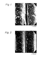
- Fig. 1 shows an electron microscopic view of a peripheral surface of the filaments of the present invention in a magnification of 3000.
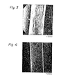
- Fig. 2 shows an electron microscopic view of a peripheral surface of a conventional filament containing 1% by weight of titanium dioxide.
- the peripheral surface of the filament as indicated in Fig. 2 is provided with extremely small projections having irregular shapes. The extremely small projections do not cause the resultant filament to exhibit the properly delustered surface appearance and a proper frictional property like those of the present invention.
- thermoplastic synthetic filaments of the present invention a mixture of 85 to 99% by weight of a thermoplastic matrix polymer with 1 to 15% by weight of a dispersed polymer which consists of at least one polysulfone polymer and which is incompatible with the matrix polymer, is prepared.
- This mixture may be prepared in such a manner that the dispersed polymer is admixed to a polymerization mixture containing monomers for producing the matrix polymer and, then, the admixed polymerization mixture is subjected to a polymerization of the monomers.
- the resultant polymerization mixture contains the resultant matrix polymer and the dispersed polymer which is non-reactive with the matrix polymer. Otherwise, the mixture may be prepared by mixing the matrix polymer with the dispersed polymer.
- the mixture is subjected to a spinning process which may be a melt spinning process, dry spinning process or wet spinning process.
- a spinning process which may be a melt spinning process, dry spinning process or wet spinning process.
- the matrix polymer is a polyester
- the mixture containing the polyester is subjected to a melt-spinning process.
- the filaments of the present invention When the filaments of the present invention are subjected to a draft zone system spinning process or a fabric made from the filaments is subjected to a raising process, it is preferable that the filaments exhibit a snap back value of 4% or less.
- the term "snap back value” used herein is defined by the equation (1): wherein SB represents a snap back value in % of the filaments, eb represents a breaking elongation in % of the filaments, rb represents a tensile recovery of % of the filaments at its break and esb represents an elongation of the filaments determined from the difference between the length of the filament at its break and the original length of the filament.
- the filaments sometimes exhibit a poor stretch-breaking property in the draft zone system spinning process and the fabric made from the filaments sometimes exhibits an unsatisfactory raising property in the raising process. That is, sometimes, the resultant spun yarn is uneven and the resultant raised fabric exhibits as uneven surface appearance.
- the filaments of the present invention exhibit a breaking modulus of 3.64 g/dtex (4 g/den) or less.
- breaking modulus used herein is defined by the equation (2): wherein Mb represents a breaking modulus in g/dtex (g/den) of a filament, sb represents a gradient in g/% of a tangential line drawn through a breaking point of the filament on the stress-strain curve of the filament, eb represents a breaking elongation in % of the filament and Do represents a titer in (dtex/den) of the filament.
- the filaments having a breaking modulus of 3.64 g/dtex (4 g/den) or less can exhibit a proper stretch-breaking property and raising property.
- the filaments of the present invention in which the matrix polymer is preferably a polyester, may be treated with an alkali aqueous solution.
- the alkali treatment results in formation of numerous concaves on the peripheral surface of the individual filament.
- Each concave is composed of a center portion thereof, which is in the form of a hemisphere, hemispheroid or hemiellipsoid, and a pair of wing portions thereof each of which is in the form of a hemicone or hemielliptic cone and extends from the center portion in opposite direction to the other along the longitudinal axis of the individual filament.
- the bottom of each wing portion is connected to the center portion.
- the center portion of the concave is derived from the removal of the protuberance by the alkali treatment.
- the wing portion of the concave is derived from the removal of a portion of the matrix polymer located just adjacent to the protuberance.
- the alkali may be selected from the group consisting of sodium hydroxide, potassium hydroxide, tetramethylammonium hydroxide, sodium carbonate and potassium carbonate.
- the most preferable alkali is sodium hydroxide or potassium hydroxide.
- the concentration of the alkali in its aqueous solution is variable depending on the type of alkali and treating conditions. However, it is preferable that the concentration of the alkali is usually in the range of from 0.1 to 40% by weight, more preferably, from 0.1 to 30% by weight.
- the alkali treatment is preferably carried out at a temperature of from room temperature to 100°C, for one minute to 4 hours. Also, it is preferable that the alkali treatment causes a reduction in the weight of the filaments to an extent of at least 10% of the original weight of the filaments. By this alkali treatment, the protuberances on the peripheral surface of the individual filament are removed so as to form the concaves in the form of hemispheroid or hemiellipsoid.
- each concave has an opening area of at least 5 pm 2. Also, it is preferable that the number of the concaves is at least one per 300 pm 2 of the peripheral surface of the individual filament.
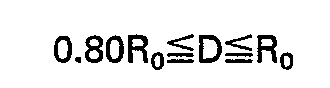
- Fig. 3 shows an electron microscopic view of a peripheral surface of an alkali-treated individual filament which has been prepared from the individual filament of the present invention as indicated in Fig. 1.
- each concave formed on the peripheral surface of the filament is composed of a hemisphere, hemispheroid or hemiellipsoid-shaped, caved center portion and a pair of hemicone or hemielliptic cone-shaped, caved wing portions, extending from the center portion in opposite directions to each other along the longitudinal axis of the filament.
- This configuration of the concave is very specific and was obtained only by alkali treating the filament of the present invention.
- the alkali treatment applied to the filaments of the present invention does not cause the resistance of the resultant filament to fibrillation to be reduced. That is, the alkali treated filaments exhibit a satisfactory resistance to abrasion.
- the treated filament is provided with numerous concaves as shown in Fig. 4.
- the concaves as shown in Fig. 4 are significantly smaller than and different in configuration from the specific concaves as shown in Fig. 3. That is, the configuration of the concaves shown in Fig. 4 is irregular.
- the filaments of the present invention can be converted into a false-twisted filament yarn having an appearance and touch similar to those of conventional hard twist filament yarn. That is, the filaments, which are polyester filaments in a partially oriented state and in the form of a filament yarn, are draw-false twisted under the conditions satisfying the relationship (3): wherein a represents a twist multiplier to be applied to the filament yarn in the range of from 0.4 to 0.9, T represents a false twisting temperature to be applied to the filament yarn in the range of from 150 to 200°C and D represents a draw ratio to be applied to the filament yarn satisfying the relationship (4): wherein R o represents a draw ratio which causes the resultant drawn filament yarn to exhibit an ultimate elongation of 30%.
- the twist multiplier (a) of the filament yarn can be calculated in accordance with the equation (5): wherein TN represents the number of twists applied to the filament yarn and De and De' represent a titer in dtex(den) of the resultant drawn, false-twisted filament yarn.
- the filament yarn to be subjected to the above mentioned draw-false twisting procedure is a partially oriented filament yarn preferably having an ultimate elongation of from 70 to 200%.
- the partially oriented filament yarn can be produced by a conventional high speed spinning process.
- the spinning speed adequate to produce the partially oriented filament yarn is variable depending on the intrinsic viscosity of the matrix polymer, the type and concentration of the dispersed polymer and the titer of the resultant individual filament.
- the spinning process is performed at a high speed of 2000 to 5500 m/sec.
- the filament yarn may consist of the filaments of the present invention alone or a blend of the filaments of the present invention with another type of filament.
- the draw-false twisting procedure is distinctive in the relatively low draw-false twisting temperature of from 150 to 200°C, from the conventional draw-false twisting procedure for conventional polyester filament yarn.
- the draw-false twisting temperature to be applied to the polyester filament yarn is 215°C or more.
- such high temperature causes the individual filaments in the yarn to be fuse-bonded to each other and the dyeing affinity of the filament yarn to be significantly changed.
- the draw-false twisting temperature is relatively low. Therefore, the change in the dyeing affinity of the filament yarn is very small and the filament yarn exhibits a satisfactory draping property.
- the individual filaments in the filament yarn are fuse-bonded to each other to a satisfactory extent.
- the drawn, false-twisted filament yarn exhibits a satisfactory weaving and knitting property.
- Example 1 The same procedures as those described in Example 1 were carried out, except that no dispersed polymer was used and the matrix polymer contained 1.0% by weight of titanium dioxide.
- the resultant drawn filament had a satisfactorily delustered appearance thereof close to that in Example 4 but not hemisphere, hemispheroid or hemiellipsoid protuberance.
- Example 3 The drawn filaments obtained in Example 3 were converted into a tricot fabric. This fabric exhibited a satisfactory high bulkiness and dyeability and a desirable dry touch.
- the used dispersed polymer consisted of a polysulfone compound which was produced and sold in the trademark of "Udel” by Union Carbide Co., U.S.A. and which was non-crystalline and incompatible with the polyethylene terephthalate used and had a glass transition temperature of 175°C.
- the mixture of the matrix polymer and the dispersed polymer in the amount as indicated in Table 2 was dried at a temperature of 160°C for 4 hours before the melt-extruding procedure.
- the spinneret used had 36 spinning orifices each having a diameter of 0.4 mm, and the extruded filamentary streams of the melted mixture was cooled by blowing cooling air at a flow linear speed of 0.3 m/sec across a spinning chimney to solidify them.
- the solidified filament was oiled and, then, wound up at a winding speed of 1200 m/min.
- the resultant undrawn filaments were preheated at a temperature of 90°C for 0.3 seconds, and drawn at a draw ratio of 3.3.
- Example 1 The same procedures as those described in Example 1 were carried out, except that no dispersed polymer was used and the matrix polymer contained 1.0% by weight of titanium dioxide.
- the resultant drawn filament had a satisfactorily delustered appearance thereof close to that in Example 4 but not hemisphere, hemispheroid or hemiellipsoid protuberance.
- Example 3 The drawn filaments obtained in Example 3 were converted into a tricot fabric. This fabric exhibited a satisfactory high bulkiness and dyeability and a desirable dry touch.
- the used dispersed polymer consisted of a polysulfone compound which was produced and sold in the trademark of "Udel” by Union Carbide Co., U.S.A. and which was non-crystalline and incompatible with the polyethylene terephthalate used and had a glass transition temperature of 175°C.
- the mixture of the matrix polymer and the dispersed polymer in the amount as indicated in Table 2 was dried at a temperature of 160°C for 4 hours before the melt-extruding procedure.
- the spinneret used had 36 spinning orifices each having a diameter of 0.4 mm, and the extruded filamentary streams of the melted mixture was cooled by blowing cooling air at a flow linear speed of 0.3 m/sec across a spinning chimney to solidify them.
- the solidified filament was oiled and, then, wound up at a winding speed of 1200 m/min.
- the resultant undrawn filaments were preheated at a temperature of 90°C for 0.3 seconds, and drawn at a draw ratio of 3.3.
- Example 1 The same procedures as those described in Example 1 were carried out, except that no dispersed polymer was used and the matrix polymer contained 1.0% by weight of titanium dioxide.
- the resultant drawn filament had a satisfactorily delustered appearance thereof close to that in Example 4 but not hemisphere, hemispheroid or hemiellipsoid protuberance.
- Example 3 The drawn filaments obtained in Example 3 were converted into a tricot fabric. This fabric exhibited a satisfactory high bulkiness and dyeability and a desirable dry touch.
- the used dispersed polymer consisted of a polysulfone compound which was produced and sold in the trademark of "Udel” by Union Carbide Co., U.S.A. and which was non-crystalline and incompatible with the polyethylene terephthalate used and had a glass transition temperature of 175°C.
- the mixture of the matrix polymer and the dispersed polymer in the amount as indicated in Table 2 was dried at a temperature of 160°C for 4 hours before the melt-extruding procedure.
- the spinneret used had 36 spinning orifices each having a diameter of 0.4 mm, and the extruded filamentary streams of the melted mixture was cooled by blowing cooling air at a flow linear speed of 0.3 m/sec across a spinning chimney to solidify them.
- the solidified filament was oiled and, then, wound up at a winding speed of 1200 m/min.
- the resultant undrawn filaments were preheated at a temperature of 90°C for 0.3 seconds, and drawn at a draw ratio of 3.3.
- Comparative Example 4 the resultant drawn individual filament had very small irregular protuberances which were derived from the fine particles of titanium dioxide, but had substantially no hemisphere or hemiellipsoid protuberance. Also, the resultant individual filament in Comparative Example 5 exhibited extremely poor tensile strength and ultimate elongation and therefore, was useless for practical use.
- Example 12 through 16 and Comparative Examples 6, 7 and 8 the amount as indicated in Table 3 of the same dispersed polymer as that described in Example 6 was mixed with the balance consisting of the same polyethylene terephthalate as that described in Example 1. The mixture was dried at 160°C for 4 hours and melt-extruded in the same manner as that described in Example 1, and the solidified filaments were oiled and, then, wound at a speed of 1500 m/min.
- the resultant undrawn filament yarn was preheated at 90°C for 0.3 seconds on a heating roll and drawn at a draw ratio of 2.8.
- the drawn filament yarn was bent-treated at 210°C by using a slit heater and wound at a speed of 800 m/min. The results are shown in Table 3.
- the filament yarns obtained in Examples 12 through 16 exhibited a satisfactory tensile strength, ultimate elongation, breaking modulus and snap back value. Therefore, these filament yarns are useful for the draft zone system spinning process and for producing a raised fabric.
- Example 17 through 21 and Comparative Examples 9 through 11 the same procedures as those described in Example 12 were carried out, except that the amount of the dispersed polymer was as indicated in Table 4, the spinning orifices each had a diameter of 0.27 mm, the extrusion of the melted mixture was carried out at a temperature of 295°C, the oiled undrawn filaments were wound at a speed of 1200 m/min and the heat treatment for the drawn filament yarn was carried out at a temperature of 220°C.
- the properties of the resultant filament yarn are indicated in Table 4.
- the filament yarns obtained in Examples 12 through 16 exhibited a satisfactory tensile strength, ultimate elongation, breaking modulus and snap back value. Therefore, these filament yarns are useful for the draft zone system spinning process and for producing a raised fabric.
- Example 17 through 21 and Comparative Examples 9 through 11 the same procedures as those described in Example 12 were carried out, except that the amount of the dispersed polymer was as indicated in Table 4, the spinning orifices each had a diameter of 0.27 mm, the extrusion of the melted mixture was carried out at a temperature of 295°C, the oiled undrawn filaments were wound at a speed of 1200 m/min and the heat treatment for the drawn filament yarn was carried out at a temperature of 220°C.
- the properties of the resultant filament yarn are indicated in Table 4.
- Each filament yarn was converted into a knitted fabric.
- the fabric was scoured and dried in an ordinary manner.
- the dried fabric was treated with an aqueous solution of sodium hydroxide in concentration as shown in Table 5 at a boiling temperature of the solution for the time period as indicated in Table 5.
- the decrease in the weight of the filament yarn is indicated in Table 5.
- the configuration, opening area and the numbers of concaves formed on the peripheral surface of the alkali-treated individual filament and the water-absorption and fibril-forming property of the alkali-treated filament yarn are shown in Table 5.
- the water absorption was determined as follows. A test specimen was completely dried and the weight (W o ) of the dried specimen was measured. The specimen was immersed in water at room temperature for 30 minutes and, then, centrifugalized for 5 minutes by using a home centrifuge. The weight (W i ) of the centrifugalized specimen was measured. The water absorption (WA) of the specimen was calculated from the following equation.
- the fibril-forming property was observed in the following manner.
- a test specimen (fabric) was rubbed 500 times with a crepe suzette fabric made of polyethylene terephthalate multifilament yarns having a yarn count of 82.5 dtex/36 filaments, and having a weight of 90 g/m 2 under a load of 5 N by using a rubbing tester. After the rubbing procedure, the surface of the specimen was observed by the naked eye.
- the opening area of the concaves were measured in the following manner. That is, after the alkali treatment, the peripheral surface of the individual filament was photographed for an electron microscopic observation at a magnification of 3000. From the photograph, the opening area of the concave was measured.
- Example 22 through 26 and Comparative Examples 12 through 14 the same procedures as those in Example 12 were carried out, except that the amount of the dispersed polymer was as indicated in Table 6, the number of the spinning orifices was 48, the linear flow speed of the cooling air was 0.3 m/sec, the winding speed for the solidified filaments was 1200 m/min, the draw ratio was 3.3 and the heat-treatment temperature for the drawn filament yarn was 230°C.
- Example 17 The same alkali treatment as mentioned in Example 17 was applied to each filament yarn which was converted into a knitted fabric, except that the concentration of sodium hydroxide in the aqueous solution was 3.0%. The results are indicated in Table 7.
- Example 27 through 44 and Comparative Examples 15 through 18 the same procedures as those described in Example 22 were carried out, except that the amount of dispersed polymer was as indicated in Table 8, the number of the spinning orifices was 36, the oiled filaments were wound at a high speed as indicated in Table 8, and the undrawn filament yarn had an ultimate elongation of about 120% and a titer of 165 dtex/36 filaments. That is, the resultant filaments were partially oriented filaments.
- the results are indicated in Table 8.
- Table 8 shows that as long as the relationship (3) is satisfied, the larger the amount of the dispersed polymer and the lower the twist multiplier and the draw ratio and the higher the draw-false twisting temperature, the better the hard twisted filament yarn-like configuration and touch.
- Example 45 through 62 and Comparative Examples 19 through 22 the same procedures as those described in Example 27 were carried out, except that the dispersed polymer was used in the amount as indicated in Table 9, the winding speed for the solidified filaments were as indicated in Table 9, and the draw-false twisting procedure was carried out under the conditions as indicated in Table 9. The results are indicated in Table 9.
Landscapes
- Engineering & Computer Science (AREA)
- Chemical & Material Sciences (AREA)
- Chemical Kinetics & Catalysis (AREA)
- General Chemical & Material Sciences (AREA)
- Textile Engineering (AREA)
- Manufacturing & Machinery (AREA)
- Artificial Filaments (AREA)
Description
- The present invention relates to thermoplastic synthetic filaments comprising 85 to 99% by weight of a thermoplastic matrix polymer and 1 to 15% by weight of a dispersed polymer which is incompatible with said matrix polymer and dispersed in the form of fine particles in said matrix polymer, and a process for producing the same.
- It is known that in order to produce thermoplastic synthetic filament having a desired gloss and frictional property, an inert inorganic substance, for example, titanium dioxide of china clay, in the form of fine solid particles is dispersed in a thermoplastic synthetic matrix polymer. That is, the inorganic particles are effective for modifying the optical and frictional properties of the filaments. The dispersed inorganic particles result in formation of numerous protuberances on the peripheral surface of the resultant individual filament. The number of the protuberances depends on the amount of the inorganic particles dispersed in the matrix polymer. These numerous protuberances create various problems on the filaments. For example, when a mixture of the thermoplastic matrix polymer with dispersed inorganic particles is subjected to a melt-spinning process, the dispersed inorganic particles cause the melt-spun filamentary streams of the melted mixture to be frequently broken. Also, when the resultant filaments are subjected to a weaving or knitting process, the protuberances on the peripheral surfaces of the filaments serve to


-


- Moreover, the thermoplastic synthetic filaments of the present invention are capable of being converted into filaments having an excellent water-absorbing property by treating them with an aqueous alkali solution in order to remove said protuberances and to cause formation of numerous corresponding concaves formed on the peripheral surface of each filament, each concave being composed of a hemisphere, hemispheroid or hemiellipsoid-shaped center portion and a pair of hemicone or hemielliptic cone-shaped wing portions thereof each extending from the center portion along the longitudinal axis of the individual filament in opposite direction to the other.
-
- Fig. 1 is a scanning electron microscopic photograph (magnification: 3000) showing a peripheral surface of a filament of the present invention having numerous hemispheroidal or hemiellipsoidal protuberances;
- Fig. 2 is a scanning electron microscopic photograph (magnification: 3000) showing a peripheral surface of a conventional filament containing 1% by weight of titanium dioxide particles and having numerous projections;
- Fig. 3 is a scanning electron microscopic photograph (magnification: 3000) showing a peripheral surface of a filament modified from the filament of the present invention as shown in Fig. 1 and having numerous specific concaves, and;
- Fig. 4 is a scanning electron microscopic photograph (magnification: 3000) showing a peripheral surface of a comparative filament modified from the conventional filament as indicated in Fig. 2 and having irregularly shaped concaves.
- The individual thermoplastic filament of the present invention comprises 85 to 99% by weight, preferably, 91 to 97% by weight, of a thermoplastic fiber-forming matrix polymer and 1 to 15% by weight, preferably, 3 to 9% by weight, of a dispersed polymer which is different from and incompatible with the matrix polymer. The dispersed polymer is dispersed in the form of numerous fine spheres, spheroids or ellipsoids, extending along the longitudinal axis of the individual filament, in the matrix polymer. In this type of filament, it is characteristic that a portion of the dispersed polymer located in the peripheral surface of the filament, forms numerous fine protuberances with a number of at least 5 per 10 pm2, on the peripheral surface of the filament. The matrix polymer usable for the present invention is not limited to a special group of thermoplastic polymer, as long as the polymer is capable of being shaped into a filament or fiber and the resultant filament or fiber exhibits satisfactory mechanical properties, for example, elasticity, rigidity, and elongation. The matrix polymer may be selected from the group consisting of fiber-forming polyesters, polyamides, polyolefins and polystyrene. The important matrix polymer for the present invention is polyester. The matrix polyester may be a polycondensation product of at least one dicarboxylic compound, for example, terephthalic acid or its reactive derivative, with at least one alkylene of fibers from corresponding starting materials and about dissolving one of the components by means of a suitable dissolving agent.
- Proceeding on the basis of the various aspects of the prior art discussed above, it is the object of the present invention to provide thermoplastic synthetic filaments having a satisfactory tensile strength, ultimate elongation, breaking modulus and snap-back value without being subject to fibrillation.
- This object according to the invention is accomplished by the thermoplastic synthetic filaments of the type indicated above and being characterized in that said dispersed polymer consists of at least one polysulfone polymer, and numerous fine protuberances consisting of said dispersed polysulfone polymer are formed in the number of at least 5 per 10 pm2 on the peripheral surface of each individual filament.
- Furthermore, it is the object of the present invention to provide a process for producing such thermoplastic synthetic filaments. This object is accomplished by the process according to patent claim 11.
- It is a specific advantage of the filaments according to this invention that they are capable of being converted into a false twisted filament yarn having a hand similar to that of conventional strongly twisted filament yarns and an excellent draping property.
- According to this aspect of the invention the inventive thermoplastic synthetic filaments in which the matrix polymer is a polyester and which are in the form of a filament yarn and in a partially oriented state, can be converted into a drawn-false twisted filament yarn by draw-false twisting the filament yarn under the conditions satisfying the relationship (3):


- Moreover, the thermoplastic synthetic filaments of the present invention are capable of being converted into filaments having an excellent water-absorbing property by treating them with an aqueous alkali solution in order to remove said protuberances and to cause formation of numerous corresponding concaves formed on the peripheral surface of each filament, each concave being composed of a hemisphere, hemispheroid or hemiellipsoid-shaped center portion and a pair of hemicone or hemielliptic cone-shaped wing portions thereof each extending from the center portion along the longitudinal axis of the individual filament in opposite direction to the other.
-
- Fig. 1 is a scanning electron microscopic photograph (magnification: 3000) showing a peripheral surface of a filament of the present invention having numerous hemispheroidal or hemiellipsoidal protuberances;
- Fig. 2 is a scanning electron microscopic photograph (magnification: 3000) showing a peripheral surface of a conventional filament containing 1% by weight of titanium dioxide particles and having numerous projections;
- Fig. 3 is a scanning electron microscopic photograph (magnification: 3000) showing a peripheral surface of a filament modified from the filament of the present invention as shown in Fig. 1 and having numerous specific concaves, and;
- Fig. 4 is a scanning electron microscopic photograph (magnification: 3000) showing a peripheral surface of a comparative filament modified from the conventional filament as indicated in Fig. 2 and having irregularly shaped concaves.
- The individual thermoplastic filament of the present invention comprises 85 to 99% by weight, preferably, 91 to 97% by weight, of a thermoplastic fiber-forming matrix polymer and 1 to 15% by weight, preferably, 3 to 9% by weight, of a dispersed polymer which is different from and incompatible with the matrix polymer. The dispersed polymer is dispersed in the form of numerous fine spheres, spheroids or ellipsoids, extending along the longitudinal axis of the individual filament, in the matrix polymer. In this type of filament, it is characteristic that a portion of the dispersed polymer located in the peripheral surface of the filament, forms numerous fine protuberances with a number of at least 5 per 10 pm2, on the peripheral surface of the filament. The matrix polymer usable for the present invention is not limited to a special group of thermoplastic polymer, as long as the polymer is capable of being shaped into a filament or fiber and the resultant filament or fiber exhibits satisfactory mechanical properties, for example, elasticity, rigidity, and elongation. The matrix polymer may be selected from the group consisting of fiber-forming polyesters, polyamides, polyolefins and polystyrene. The important matrix polymer for the present invention is polyester. The matrix polyester may be a polycondensation product of at least one dicarboxylic compound, for example, terephthalic acid or its reactive derivative, with at least one alkylene glycol component, for example, ethylene glycol, propylene glycol, butylene glycol. Preferably, the matrix polyester is polyethylene terephthalate, polybutylene terephthalate or a copolyester containing 75 molar% or more, more preferably, 85 molar% or more, of the recurring alkylene terephthalate units derived from the esterification reaction of an alkylene glycol with terephthalic acid or its functional derivative. Also, it is preferable that the matrix polyester has a limited (intrinsic) viscosity of 0.4 or more measured in o-chlorophenol at a temperature of 35°C.
- The matrix polymer may contain, as additives, a catalyst residue, ether-generation-preventing agent, stabilizer, flame retardant, anti-static agent, hydrophilicity-enhancing agent, coloring material, optical brightening agent, and/or delustering agent.
- The dispersed polymer usable for the present invention consists of at least one polysulfone polymer which is different from, non-reactive to and incompatible with the matrix polymer. It is preferable that the dispersed polymer is non-crystalline and has a glass transition temperature of at least 150°C. The glass transition temperature of the dispersed polymer can be determined by the method described in U.S. Patent No. 2,556,295. The non-crystallinity of the dispersed polymer can be determined by the X-ray wide angle diffractometry. When no diffraction point or line is found in the diffraction X-ray photograph of the dispersed polymer, it is deemed that the dispersed polymer is non-crystalline.
- The dispersed polymer may be selected from polysulfons having the recurring units of the formulae (I) through (IV):


- The dispersed polymer is used in an amount of from 1 to 15% by weight, preferably, from 3 to 9% by weight. When the amount of the dispersed polymer is less than 1% by weight, the number of the resultant protuberances is less than 5 per 10 J.lm2 of the peripheral surface of the resultant filament, and, therefore, the surface appearance and the frictional property of the resultant filament are unsatisfactory. Also, more than 15% by weight of the dispersed polymer causes the resultant filament to exhibit a poor mechanical strength and, therefore, to be practically useless.
- When a mixture of the matrix polymer and the dispersed polymer is melt-spun into filaments, at an elevated temperature higher than the melting point of the matrix polymer, the resultant filaments are provided with numerous fine protuberances formed on the peripheral surface of each individual filament. The density of the protuberances is at least 5 per 10 µm2 of the peripheral surface of the individual filament. In this density, the protuberances are effective for delustering the surface of the resultant filament and for decreasing the dynamic friction of the filament peripheral surfaces with each other and with metal surfaces. Therefore, the filament exhibits a satisfactory delustered surface appearance and a satisfactory frictional property and hand. The decreased dynamic frictional property of the filament is effective in increasing the draping property of the fabric made from the filament. Preferably, the protuberances are each in the form of a hemispheroid or hemiellipsoid extending along the longitudinal axis of the individual filament. Also it is preferable that the area of the bottoms of the protuberances is 0.5 pm2 or more.
- The filaments of the present invention may have a circular cross-sectional profile or an irregular cross-sectional profile, for example, trilobal or another multilobal cross-sectional profile. The irregular cross-sectional profile is effective for imparting a silk-like gloss and hand to the filament.
- The dispersed polymer particles dispersed in the matrix polymer in the filaments are effective for enhancing the dyeing property of the filaments, because numerous small voids are formed in the interface between the matrix polymer phase and the dispersed polymer phase. Also, since there is a small difference in the thermal shrinkage between the matrix polymer phase and the dispersed polymer phase, the woven or knitted fabric made from the filaments of the present invention can have a preferable bulkiness and hand.
- Fig. 1 shows an electron microscopic view of a peripheral surface of the filaments of the present invention in a magnification of 3000. Also, Fig. 2 shows an electron microscopic view of a peripheral surface of a conventional filament containing 1% by weight of titanium dioxide. The peripheral surface of the filament as indicated in Fig. 2 is provided with extremely small projections having irregular shapes. The extremely small projections do not cause the resultant filament to exhibit the properly delustered surface appearance and a proper frictional property like those of the present invention.
- In the preparation of the thermoplastic synthetic filaments of the present invention, a mixture of 85 to 99% by weight of a thermoplastic matrix polymer with 1 to 15% by weight of a dispersed polymer which consists of at least one polysulfone polymer and which is incompatible with the matrix polymer, is prepared. This mixture may be prepared in such a manner that the dispersed polymer is admixed to a polymerization mixture containing monomers for producing the matrix polymer and, then, the admixed polymerization mixture is subjected to a polymerization of the monomers. The resultant polymerization mixture contains the resultant matrix polymer and the dispersed polymer which is non-reactive with the matrix polymer. Otherwise, the mixture may be prepared by mixing the matrix polymer with the dispersed polymer.
- The mixture is subjected to a spinning process which may be a melt spinning process, dry spinning process or wet spinning process. When the matrix polymer is a polyester, the mixture containing the polyester is subjected to a melt-spinning process.
- When the filaments of the present invention are subjected to a draft zone system spinning process or a fabric made from the filaments is subjected to a raising process, it is preferable that the filaments exhibit a snap back value of 4% or less. The term "snap back value" used herein is defined by the equation (1):

- Also, it is preferable that the filaments of the present invention exhibit a breaking modulus of 3.64 g/dtex (4 g/den) or less. The term "breaking modulus" used herein is defined by the equation (2):

- The filaments having a breaking modulus of 3.64 g/dtex (4 g/den) or less can exhibit a proper stretch-breaking property and raising property.
- The filaments of the present invention, in which the matrix polymer is preferably a polyester, may be treated with an alkali aqueous solution. The alkali treatment results in formation of numerous concaves on the peripheral surface of the individual filament. Each concave is composed of a center portion thereof, which is in the form of a hemisphere, hemispheroid or hemiellipsoid, and a pair of wing portions thereof each of which is in the form of a hemicone or hemielliptic cone and extends from the center portion in opposite direction to the other along the longitudinal axis of the individual filament. The bottom of each wing portion is connected to the center portion. The center portion of the concave is derived from the removal of the protuberance by the alkali treatment. Also, the wing portion of the concave is derived from the removal of a portion of the matrix polymer located just adjacent to the protuberance.
- The alkali may be selected from the group consisting of sodium hydroxide, potassium hydroxide, tetramethylammonium hydroxide, sodium carbonate and potassium carbonate. The most preferable alkali is sodium hydroxide or potassium hydroxide.
- The concentration of the alkali in its aqueous solution is variable depending on the type of alkali and treating conditions. However, it is preferable that the concentration of the alkali is usually in the range of from 0.1 to 40% by weight, more preferably, from 0.1 to 30% by weight. The alkali treatment is preferably carried out at a temperature of from room temperature to 100°C, for one minute to 4 hours. Also, it is preferable that the alkali treatment causes a reduction in the weight of the filaments to an extent of at least 10% of the original weight of the filaments. By this alkali treatment, the protuberances on the peripheral surface of the individual filament are removed so as to form the concaves in the form of hemispheroid or hemiellipsoid.
- In the alkali-treated individual filament, it is preferable that each concave has an opening area of at least 5 pm2. Also, it is preferable that the number of the concaves is at least one per 300 pm2 of the peripheral surface of the individual filament.
- Fig. 3 shows an electron microscopic view of a peripheral surface of an alkali-treated individual filament which has been prepared from the individual filament of the present invention as indicated in Fig. 1. Referring to Fig. 3, each concave formed on the peripheral surface of the filament is composed of a hemisphere, hemispheroid or hemiellipsoid-shaped, caved center portion and a pair of hemicone or hemielliptic cone-shaped, caved wing portions, extending from the center portion in opposite directions to each other along the longitudinal axis of the filament. This configuration of the concave is very specific and was obtained only by alkali treating the filament of the present invention.
- Also, it is important that the alkali treatment applied to the filaments of the present invention does not cause the resistance of the resultant filament to fibrillation to be reduced. That is, the alkali treated filaments exhibit a satisfactory resistance to abrasion.
- When the conventional filament as shown in Fig. 2 is treated with the alkali aqueous solution, the treated filament is provided with numerous concaves as shown in Fig. 4. The concaves as shown in Fig. 4 are significantly smaller than and different in configuration from the specific concaves as shown in Fig. 3. That is, the configuration of the concaves shown in Fig. 4 is irregular.
- The filaments of the present invention can be converted into a false-twisted filament yarn having an appearance and touch similar to those of conventional hard twist filament yarn. That is, the filaments, which are polyester filaments in a partially oriented state and in the form of a filament yarn, are draw-false twisted under the conditions satisfying the relationship (3):

- The twist multiplier (a) of the filament yarn can be calculated in accordance with the equation (5):

- The filament yarn to be subjected to the above mentioned draw-false twisting procedure is a partially oriented filament yarn preferably having an ultimate elongation of from 70 to 200%. The partially oriented filament yarn can be produced by a conventional high speed spinning process. The spinning speed adequate to produce the partially oriented filament yarn is variable depending on the intrinsic viscosity of the matrix polymer, the type and concentration of the dispersed polymer and the titer of the resultant individual filament. Usually, the spinning process is performed at a high speed of 2000 to 5500 m/sec.
- In the above-mentioned draw-false twisting procedure, the filament yarn may consist of the filaments of the present invention alone or a blend of the filaments of the present invention with another type of filament.
- The draw-false twisting procedure is distinctive in the relatively low draw-false twisting temperature of from 150 to 200°C, from the conventional draw-false twisting procedure for conventional polyester filament yarn. In order to produce a drawn, false twisted polyester filament yarn having a hard twist yarn-like touch, it is necessary that the draw-false twisting temperature to be applied to the polyester filament yarn is 215°C or more. However, such high temperature causes the individual filaments in the yarn to be fuse-bonded to each other and the dyeing affinity of the filament yarn to be significantly changed. However, in the above-mentioned draw-false twisting procedure, the draw-false twisting temperature is relatively low. Therefore, the change in the dyeing affinity of the filament yarn is very small and the filament yarn exhibits a satisfactory draping property. However, the individual filaments in the filament yarn are fuse-bonded to each other to a satisfactory extent.
- The drawn, false-twisted filament yarn exhibits a satisfactory weaving and knitting property. In orderto

- The same procedures as those described in Example 1 were carried out, except that no dispersed polymer was used and the matrix polymer contained 1.0% by weight of titanium dioxide.
- The resultant drawn filament had a satisfactorily delustered appearance thereof close to that in Example 4 but not hemisphere, hemispheroid or hemiellipsoid protuberance.
- The drawn filaments obtained in Example 3 were converted into a tricot fabric. This fabric exhibited a satisfactory high bulkiness and dyeability and a desirable dry touch.
- In each of the Examples 7 through 11 and Comparative Examples 4 and 5, the same procedures as those described in Example 1 were carried out with the following exception.
- The used dispersed polymer consisted of a polysulfone compound which was produced and sold in the trademark of "Udel" by Union Carbide Co., U.S.A. and which was non-crystalline and incompatible with the polyethylene terephthalate used and had a glass transition temperature of 175°C.
- The mixture of the matrix polymer and the dispersed polymer in the amount as indicated in Table 2 was dried at a temperature of 160°C for 4 hours before the melt-extruding procedure.
- The spinneret used had 36 spinning orifices each having a diameter of 0.4 mm, and the extruded filamentary streams of the melted mixture was cooled by blowing cooling air at a flow linear speed of 0.3 m/sec across a spinning chimney to solidify them.
- The solidified filament was oiled and, then, wound up at a winding speed of 1200 m/min.
- The resultant undrawn filaments were preheated at a temperature of 90°C for 0.3 seconds, and drawn at a draw ratio of 3.3.
- The properties of the resultant filaments are indicated in Table 2.
- The same procedures as those described in Example 1 were carried out, except that no dispersed polymer was used and the matrix polymer contained 1.0% by weight of titanium dioxide.
- The resultant drawn filament had a satisfactorily delustered appearance thereof close to that in Example 4 but not hemisphere, hemispheroid or hemiellipsoid protuberance.
- The drawn filaments obtained in Example 3 were converted into a tricot fabric. This fabric exhibited a satisfactory high bulkiness and dyeability and a desirable dry touch.
- In each of the Examples 7 through 11 and Comparative Examples 4 and 5, the same procedures as those described in Example 1 were carried out with the following exception.
- The used dispersed polymer consisted of a polysulfone compound which was produced and sold in the trademark of "Udel" by Union Carbide Co., U.S.A. and which was non-crystalline and incompatible with the polyethylene terephthalate used and had a glass transition temperature of 175°C.
- The mixture of the matrix polymer and the dispersed polymer in the amount as indicated in Table 2 was dried at a temperature of 160°C for 4 hours before the melt-extruding procedure.
- The spinneret used had 36 spinning orifices each having a diameter of 0.4 mm, and the extruded filamentary streams of the melted mixture was cooled by blowing cooling air at a flow linear speed of 0.3 m/sec across a spinning chimney to solidify them.
- The solidified filament was oiled and, then, wound up at a winding speed of 1200 m/min.
- The resultant undrawn filaments were preheated at a temperature of 90°C for 0.3 seconds, and drawn at a draw ratio of 3.3.
- The properties of the resultant filaments are indicated in Table 2.
- The same procedures as those described in Example 1 were carried out, except that no dispersed polymer was used and the matrix polymer contained 1.0% by weight of titanium dioxide.
- The resultant drawn filament had a satisfactorily delustered appearance thereof close to that in Example 4 but not hemisphere, hemispheroid or hemiellipsoid protuberance.
- The drawn filaments obtained in Example 3 were converted into a tricot fabric. This fabric exhibited a satisfactory high bulkiness and dyeability and a desirable dry touch.
- In each of the Examples 7 through 11 and Comparative Examples 4 and 5, the same procedures as those described in Example 1 were carried out with the following exception.
- The used dispersed polymer consisted of a polysulfone compound which was produced and sold in the trademark of "Udel" by Union Carbide Co., U.S.A. and which was non-crystalline and incompatible with the polyethylene terephthalate used and had a glass transition temperature of 175°C.
- The mixture of the matrix polymer and the dispersed polymer in the amount as indicated in Table 2 was dried at a temperature of 160°C for 4 hours before the melt-extruding procedure.
- The spinneret used had 36 spinning orifices each having a diameter of 0.4 mm, and the extruded filamentary streams of the melted mixture was cooled by blowing cooling air at a flow linear speed of 0.3 m/sec across a spinning chimney to solidify them.
- The solidified filament was oiled and, then, wound up at a winding speed of 1200 m/min.
- The resultant undrawn filaments were preheated at a temperature of 90°C for 0.3 seconds, and drawn at a draw ratio of 3.3.
- The properties of the resultant filaments are indicated in Table 2.

- In Comparative Example 4, the resultant drawn individual filament had very small irregular protuberances which were derived from the fine particles of titanium dioxide, but had substantially no hemisphere or hemiellipsoid protuberance. Also, the resultant individual filament in Comparative Example 5 exhibited extremely poor tensile strength and ultimate elongation and therefore, was useless for practical use.
- In each of the Examples 12 through 16 and Comparative Examples 6, 7 and 8, the amount as indicated in Table 3 of the same dispersed polymer as that described in Example 6 was mixed with the balance consisting of the same polyethylene terephthalate as that described in Example 1. The mixture was dried at 160°C for 4 hours and melt-extruded in the same manner as that described in Example 1, and the solidified filaments were oiled and, then, wound at a speed of 1500 m/min.
- The resultant undrawn filament yarn was preheated at 90°C for 0.3 seconds on a heating roll and drawn at a draw ratio of 2.8. The drawn filament yarn was bent-treated at 210°C by using a slit heater and wound at a speed of 800 m/min. The results are shown in Table 3.

- In each of Comparative Examples 6 and 7, the resultant filament yarn exhibited a large snap back value and breaking modulus and, therefore, is not suitable for the draft zone system spinning process and raising process. Also, the resultant filament yarn in Comparative Example 8 exhibited an extremely poor tensile strength and ultimate elongation and, therefore, is useless for practical use.
- The filament yarns obtained in Examples 12 through 16 exhibited a satisfactory tensile strength, ultimate elongation, breaking modulus and snap back value. Therefore, these filament yarns are useful for the draft zone system spinning process and for producing a raised fabric.
- In each of the Examples 17 through 21 and Comparative Examples 9 through 11, the same procedures as those described in Example 12 were carried out, except that the amount of the dispersed polymer was as indicated in Table 4, the spinning orifices each had a diameter of 0.27 mm, the extrusion of the melted mixture was carried out at a temperature of 295°C, the oiled undrawn filaments were wound at a speed of 1200 m/min and the heat treatment for the drawn filament yarn was carried out at a temperature of 220°C. The properties of the resultant filament yarn are indicated in Table 4.
- In each of Comparative Examples 6 and 7, the resultant filament yarn exhibited a large snap back value and breaking modulus and, therefore, is not suitable for the draft zone system spinning process and raising process. Also, the resultant filament yarn in Comparative Example 8 exhibited an extremely poor tensile strength and ultimate elongation and, therefore, is useless for practical use.
- The filament yarns obtained in Examples 12 through 16 exhibited a satisfactory tensile strength, ultimate elongation, breaking modulus and snap back value. Therefore, these filament yarns are useful for the draft zone system spinning process and for producing a raised fabric.
- In each of the Examples 17 through 21 and Comparative Examples 9 through 11, the same procedures as those described in Example 12 were carried out, except that the amount of the dispersed polymer was as indicated in Table 4, the spinning orifices each had a diameter of 0.27 mm, the extrusion of the melted mixture was carried out at a temperature of 295°C, the oiled undrawn filaments were wound at a speed of 1200 m/min and the heat treatment for the drawn filament yarn was carried out at a temperature of 220°C. The properties of the resultant filament yarn are indicated in Table 4.
- Each filament yarn was converted into a knitted fabric. The fabric was scoured and dried in an ordinary manner. The dried fabric was treated with an aqueous solution of sodium hydroxide in concentration as shown in Table 5 at a boiling temperature of the solution for the time period as indicated in Table 5. The decrease in the weight of the filament yarn is indicated in Table 5. Also, the configuration, opening area and the numbers of concaves formed on the peripheral surface of the alkali-treated individual filament and the water-absorption and fibril-forming property of the alkali-treated filament yarn are shown in Table 5.

- The water absorption was determined as follows. A test specimen was completely dried and the weight (Wo) of the dried specimen was measured. The specimen was immersed in water at room temperature for 30 minutes and, then, centrifugalized for 5 minutes by using a home centrifuge. The weight (Wi) of the centrifugalized specimen was measured. The water absorption (WA) of the specimen was calculated from the following equation.

- The fibril-forming property was observed in the following manner. A test specimen (fabric) was rubbed 500 times with a crepe suzette fabric made of polyethylene terephthalate multifilament yarns having a yarn count of 82.5 dtex/36 filaments, and having a weight of 90 g/m2 under a load of 5 N by using a rubbing tester. After the rubbing procedure, the surface of the specimen was observed by the naked eye.
- The opening area of the concaves were measured in the following manner. That is, after the alkali treatment, the peripheral surface of the individual filament was photographed for an electron microscopic observation at a magnification of 3000. From the photograph, the opening area of the concave was measured.
- In each of the Examples 22 through 26 and Comparative Examples 12 through 14, the same procedures as those in Example 12 were carried out, except that the amount of the dispersed polymer was as indicated in Table 6, the number of the spinning orifices was 48, the linear flow speed of the cooling air was 0.3 m/sec, the winding speed for the solidified filaments was 1200 m/min, the draw ratio was 3.3 and the heat-treatment temperature for the drawn filament yarn was 230°C.
- The properties of the resultant filament yarn are indicated in Table 6.

- The same alkali treatment as mentioned in Example 17 was applied to each filament yarn which was converted into a knitted fabric, except that the concentration of sodium hydroxide in the aqueous solution was 3.0%. The results are indicated in Table 7.

- From Tables 5 and 6, it is clear that when the filament yarn of the present invention (Examples 17 through 26) was alkali treated to an extent that the decrease in weight was 10% or more, the resultant concaves had a specific shape and exhibited an excellent water absorption of 40% or more and a satisfactory resistance to the formation of fibrils.
- In each of the Examples 27 through 44 and Comparative Examples 15 through 18, the same procedures as those described in Example 22 were carried out, except that the amount of dispersed polymer was as indicated in Table 8, the number of the spinning orifices was 36, the oiled filaments were wound at a high speed as indicated in Table 8, and the undrawn filament yarn had an ultimate elongation of about 120% and a titer of 165 dtex/36 filaments. That is, the resultant filaments were partially oriented filaments.
- Each resultant filament yarn was draw-false twisted under the conditions as indicated in Table 8 by using a Draw-False twister (Type FW-III, made by Teijin Seiki K.K. Japan; the length of heater=1.0 m), and the drawn, false twisted filament yarn was relaxed at a temperature of 200°C while overfeeding the yarn at an overfeed of 5% by using a non-contact type heater, and wound at a speed of 100 m/min. The results are indicated in Table 8.


- In Comparative Examples 16 and 17 in which the dispersed polymer was used in an amount less than 1%, the draw-false twisting procedure applied to the resultant filament yarns having substantially no protuberances failed to obtain hard twist filament yarn-like false twisted yarns, even when a high draw-false twisting temperature of 200°C was applied to the filament yarns. In the Comparative Example 15 in which no dispersed polymer was used and the resultant filaments had no protuberances, an excessively high draw-false twisting temperature of 235°C was applied to the filament yarn in order to cause the resultant yarn to exhibit a hard twist filament yarn-like configuration and touch.
- In Comparative Example 18, the resultant filament yarn containing 16.0% of the dispersed polymer exhibited an extremely poor mechanical strength.
- In Examples 27, 28, 30 through 34, 36, 37 and 39 through 44 wherein the draw-false twisting procedures were carried out under the conditions satisfying the relationship (3), the resultant filament yarns all exhibited satisfactory hard twist filament yarn-like configuration and touch. However, in Examples 29, 35 and 38 wherein the draw-false twisting procedures were carried out under conditions not satisfying the relationship (3), the resultant filament yarns exhibited unsatisfactory touch and degree of fuse bonding of the individual filaments.
- Table 8 shows that as long as the relationship (3) is satisfied, the larger the amount of the dispersed polymer and the lower the twist multiplier and the draw ratio and the higher the draw-false twisting temperature, the better the hard twisted filament yarn-like configuration and touch.
- In each of the Examples 45 through 62 and Comparative Examples 19 through 22, the same procedures as those described in Example 27 were carried out, except that the dispersed polymer was used in the amount as indicated in Table 9, the winding speed for the solidified filaments were as indicated in Table 9, and the draw-false twisting procedure was carried out under the conditions as indicated in Table 9. The results are indicated in Table 9.

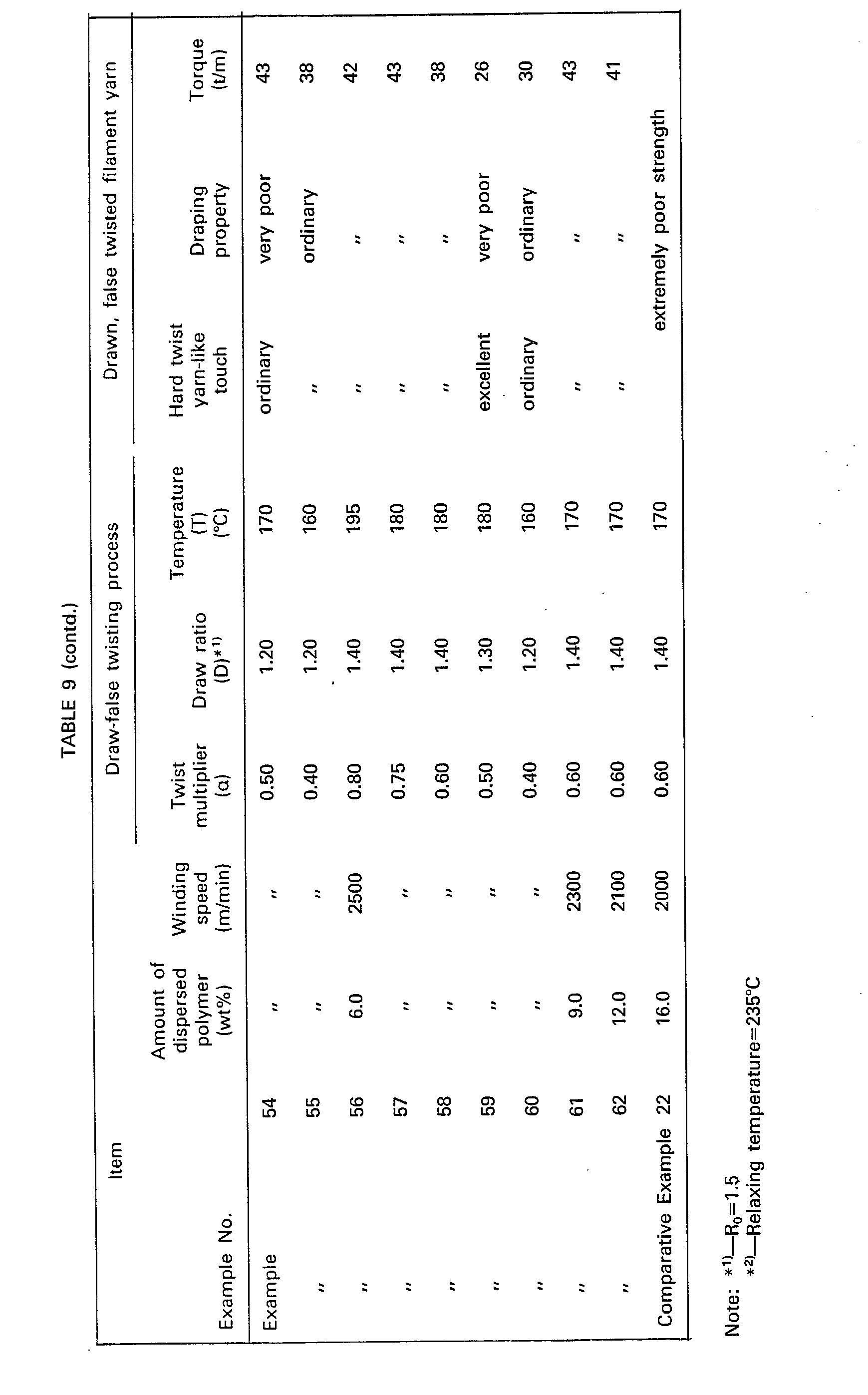
- In Comparative Example 19 wherein the filaments contained no dispersed polymer, the draw-false twisting procedure was carried out at an excessively high temperature of 235°C. The resultant filament yarn exhibited poor draping property.
- In Comparative Example 20 and 21 wherein the filaments contained zero or 0.5% by weight of the dispersed polymer, the draw-false twisting procedures were carried out at a relatively low twist multiplier of 0.40, draw ratio of 1.2 and temperature of 160°C. The resultant filament yarns exhibited an unsatisfactory hard twist filament yarn like configuration and touch.
- In Comparative Example 22 wherein the dispersed polymer was used in a large amount, 16% by weight, the resultant filament yarn could not be draw-false twisted because of its extremely poor mechanical strength.
- In Examples 45 through 49, 51 through 53, 55 through 58 and 60 through 62, wherein the draw-false twisting conditions satisfied the relationship (3), the resultant filament yarns exhibited satisfactory hard twist filament yarn-like configuration and touch and draping property. However, in Examples 50, 54, and 59, wherein the draw-false twisting conditions did not satisfy the relationship (3), the resultant filament yarns exhibited a poor draping property.
Claims (26)




Applications Claiming Priority (11)
| Application Number | Priority Date | Filing Date | Title |
|---|---|---|---|
| JP30259/80 | 1980-03-12 | ||
| JP3025980A JPS56127660A (en) | 1980-03-12 | 1980-03-12 | Thermoplastic formed product |
| JP3394880A JPS56134213A (en) | 1980-03-19 | 1980-03-19 | Polyester fiber |
| JP33948/80 | 1980-03-19 | ||
| JP33947/80 | 1980-03-19 | ||
| JP3394780A JPS56131663A (en) | 1980-03-19 | 1980-03-19 | Production of thermoplastic molded article |
| JP7418480A JPS57145A (en) | 1980-06-04 | 1980-06-04 | Porous molded article |
| JP7486280A JPS571727A (en) | 1980-06-05 | 1980-06-05 | Manufacture of porous molded form |
| JP11112080A JPS5739228A (en) | 1980-08-14 | 1980-08-14 | Production of hard twisted type processed yarn with improved drapeng property |
| JP11111980A JPS5739227A (en) | 1980-08-14 | 1980-08-14 | Production of hard twisted type processed yarn |
| JP13225580A JPS5761718A (en) | 1980-09-25 | 1980-09-25 | Polyester fiber |
Publications (2)
| Publication Number | Publication Date |
|---|---|
| EP0035796A1 EP0035796A1 (en) | 1981-09-16 |
| EP0035796B1 true EP0035796B1 (en) | 1986-06-04 |
Family
ID=27572103
Family Applications (1)
| Application Number | Title | Priority Date | Filing Date |
|---|---|---|---|
| EP81101790A Expired EP0035796B1 (en) | 1980-03-12 | 1981-03-11 | Thermoplastic synthetic filaments and process for producing the same |
Country Status (1)
| Country | Link |
|---|---|
| EP (1) | EP0035796B1 (en) |
Cited By (2)
| Publication number | Priority date | Publication date | Assignee | Title |
|---|---|---|---|---|
| EP2123189A1 (en) | 2008-05-20 | 2009-11-25 | Braun Gmbh | Toothbrush, toothbrush filament and method for manufacturing same |
| US7943699B2 (en) | 2003-10-21 | 2011-05-17 | E. I. Du Pont De Nemours And Company | Ethylene copolymer modified oriented polyester films, tapes, fibers and nonwoven textiles |
Families Citing this family (10)
| Publication number | Priority date | Publication date | Assignee | Title |
|---|---|---|---|---|
| DE3271192D1 (en) * | 1981-11-23 | 1986-06-19 | Ici Plc | Process of melt spinning of a blend of a fibre-forming polymer and an immiscible polymer and melt spun fibres produced by such process |
| GB8316323D0 (en) * | 1983-06-15 | 1983-07-20 | Ici Plc | Producing polyamide fibre |
| HUT51579A (en) * | 1987-11-24 | 1990-05-28 | Mta Termeszettu Domanyi Kutato | Process for producing hydraulic bonded objects containing synthetic strengthening fibres |
| KR940005836A (en) * | 1992-05-14 | 1994-03-22 | 히로시 이따가끼 | Polyester fiber excellent in deep color and its manufacturing method |
| US5993712A (en) * | 1997-02-25 | 1999-11-30 | Lurgi Zimmer Aktiengesellschaft | Process for the processing of polymer mixtures into filaments |
| ITMI20021373A1 (en) | 2002-06-21 | 2003-12-22 | Effeci Engineering S A S Di Fo | POLYMERIC COMPOUNDS AND THEIR USE |
| CN1926193A (en) | 2004-03-05 | 2007-03-07 | 纳幕尔杜邦公司 | Ethylene copolymer-modified polyamide product |
| EP2198744B1 (en) | 2008-12-19 | 2011-11-09 | Braun GmbH | Bristle tuft and toothbrush with bristle tuft |
| WO2021035122A1 (en) * | 2019-08-22 | 2021-02-25 | Penn Color, Inc. | Delustered fiber |
| CN116043362B (en) * | 2022-12-13 | 2024-02-27 | 东华大学 | A kind of polymer fiber with surface concave and convex structure and preparation method thereof |
Citations (7)
| Publication number | Priority date | Publication date | Assignee | Title |
|---|---|---|---|---|
| EP0022182A1 (en) * | 1979-06-11 | 1981-01-14 | Teijin Limited | Synthetic polyester pulp and process for preparing same |
| EP0023664A1 (en) * | 1979-07-26 | 1981-02-11 | Teijin Limited | Process for producing the same of hollow water-absorbing polyester filaments |
| EP0033592A2 (en) * | 1980-01-31 | 1981-08-12 | Imperial Chemical Industries Plc | Conductive polymers, fibres made therefrom and process for manufacture |
| EP0037968A2 (en) * | 1980-04-07 | 1981-10-21 | Teijin Limited | Woven or knitted polyester multifilament fabric |
| EP0038429A2 (en) * | 1980-03-25 | 1981-10-28 | Teijin Limited | Antistatic polyester fibers |
| EP0049412A1 (en) * | 1980-09-25 | 1982-04-14 | Teijin Limited | A polyester multifilament yarn and a process for manufacturing the same |
| EP0060819A1 (en) * | 1981-03-05 | 1982-09-22 | Nordiskafilt Ab | A method of manufacturing a fabric having soil-release properties, particularly forming fabrics used in papermaking machines and cellulose machines, and filter cloths used in the papermaking and cellulose industries and related industries |
Family Cites Families (4)
| Publication number | Priority date | Publication date | Assignee | Title |
|---|---|---|---|---|
| DE1669544B2 (en) * | 1966-03-15 | 1974-06-20 | Teijin Ltd., Osaka (Japan) | Textile fibers with voids and processes for their manufacture |
| JPS479851B1 (en) * | 1968-10-11 | 1972-03-23 | ||
| US3640944A (en) * | 1969-01-31 | 1972-02-08 | Minnesota Mining & Mfg | Modified polyester film for punched tapes |
| JPS54120728A (en) * | 1978-03-08 | 1979-09-19 | Kuraray Co Ltd | Fine synthetic fiber having complicatedly roughened surface and its production |
-
1981
- 1981-03-11 EP EP81101790A patent/EP0035796B1/en not_active Expired
Patent Citations (7)
| Publication number | Priority date | Publication date | Assignee | Title |
|---|---|---|---|---|
| EP0022182A1 (en) * | 1979-06-11 | 1981-01-14 | Teijin Limited | Synthetic polyester pulp and process for preparing same |
| EP0023664A1 (en) * | 1979-07-26 | 1981-02-11 | Teijin Limited | Process for producing the same of hollow water-absorbing polyester filaments |
| EP0033592A2 (en) * | 1980-01-31 | 1981-08-12 | Imperial Chemical Industries Plc | Conductive polymers, fibres made therefrom and process for manufacture |
| EP0038429A2 (en) * | 1980-03-25 | 1981-10-28 | Teijin Limited | Antistatic polyester fibers |
| EP0037968A2 (en) * | 1980-04-07 | 1981-10-21 | Teijin Limited | Woven or knitted polyester multifilament fabric |
| EP0049412A1 (en) * | 1980-09-25 | 1982-04-14 | Teijin Limited | A polyester multifilament yarn and a process for manufacturing the same |
| EP0060819A1 (en) * | 1981-03-05 | 1982-09-22 | Nordiskafilt Ab | A method of manufacturing a fabric having soil-release properties, particularly forming fabrics used in papermaking machines and cellulose machines, and filter cloths used in the papermaking and cellulose industries and related industries |
Cited By (3)
| Publication number | Priority date | Publication date | Assignee | Title |
|---|---|---|---|---|
| US7943699B2 (en) | 2003-10-21 | 2011-05-17 | E. I. Du Pont De Nemours And Company | Ethylene copolymer modified oriented polyester films, tapes, fibers and nonwoven textiles |
| EP2123189A1 (en) | 2008-05-20 | 2009-11-25 | Braun Gmbh | Toothbrush, toothbrush filament and method for manufacturing same |
| US8099821B2 (en) | 2008-05-20 | 2012-01-24 | Braun Gmbh | Toothbrush, toothbrush filament and method for manufacturing same |
Also Published As
| Publication number | Publication date |
|---|---|
| EP0035796A1 (en) | 1981-09-16 |
Similar Documents
| Publication | Publication Date | Title |
|---|---|---|
| US4391872A (en) | Hollow water-absorbing polyester filament textile material | |
| US3718534A (en) | Spontaneously crimping synthetic composite filament and process of manufacturing the same | |
| JP3769013B2 (en) | Hollow nylon filament, hollow nylon yarn, and production method thereof | |
| EP0035796B1 (en) | Thermoplastic synthetic filaments and process for producing the same | |
| JP2014156685A (en) | Poly (trimethylene terephthalate) fine denier yarns | |
| US4356234A (en) | Thermoplastic synthetic filaments and process for producing the same | |
| US4364983A (en) | Multifilament yarn of individual filaments of the multicomponent matrix/segment type which has been falsetwisted, a component thereof shrunk, a component thereof heatset; fabrics comprising said | |
| EP0207489A2 (en) | Highly-shrinkable polyester fiber, process for preparation thereof, blended polyester yarn and process for preparation thereof | |
| US4098946A (en) | Polyester filament containing organophilic kaolin | |
| EP0140559B1 (en) | Improved high speed process for forming fully drawn polyester yarn | |
| JP2544783B2 (en) | Composite fiber and manufacturing method thereof | |
| JPS636648B2 (en) | ||
| Gupta | Manufactured textile fibers | |
| JPH0260763B2 (en) | ||
| JPH0120627B2 (en) | ||
| JP3752445B2 (en) | Polyester multi fiber | |
| JP2623528B2 (en) | Super absorbent woven and knitted fabric | |
| JPS5812372B2 (en) | Trilobal polyester | |
| KR840000779B1 (en) | Absorbent Hollow Polyester Filament | |
| JP2571834B2 (en) | Polyester fiber having hemp-like feeling and method for producing the same | |
| JPH08291463A (en) | Polyester hollow thin fiber and method for producing the same | |
| JP2555136B2 (en) | Microporous polyester fiber manufacturing method | |
| JPH08291462A (en) | Polyester hollow thin fiber and method for producing the same | |
| JPH01272862A (en) | Cation dyeable polyester fiber excellent in feeling and production thereof | |
| KR900000141B1 (en) | Manufacturing method of two-component composite yarn |
Legal Events
| Date | Code | Title | Description |
|---|---|---|---|
| PUAI | Public reference made under article 153(3) epc to a published international application that has entered the european phase |
Free format text: ORIGINAL CODE: 0009012 |
|
| AK | Designated contracting states |
Designated state(s): DE FR GB |
|
| 17P | Request for examination filed |
Effective date: 19820309 |
|
| GRAA | (expected) grant |
Free format text: ORIGINAL CODE: 0009210 |
|
| AK | Designated contracting states |
Kind code of ref document: B1 Designated state(s): DE FR GB |
|
| REF | Corresponds to: |
Ref document number: 3174757 Country of ref document: DE Date of ref document: 19860710 |
|
| EN | Fr: translation not filed | ||
| PLBI | Opposition filed |
Free format text: ORIGINAL CODE: 0009260 |
|
| 26 | Opposition filed |
Opponent name: RHONE-POULENC FIBRES S.A. Effective date: 19870227 |
|
| RDAG | Patent revoked |
Free format text: ORIGINAL CODE: 0009271 |
|
| STAA | Information on the status of an ep patent application or granted ep patent |
Free format text: STATUS: PATENT REVOKED |
|
| 27W | Patent revoked |
Effective date: 19870410 |
|
| GBPR | Gb: patent revoked under art. 102 of the ep convention designating the uk as contracting state |