EP0035603B1 - Rail with a double-t profile for suspension railways - Google Patents
Rail with a double-t profile for suspension railways Download PDFInfo
- Publication number
- EP0035603B1 EP0035603B1 EP80200218A EP80200218A EP0035603B1 EP 0035603 B1 EP0035603 B1 EP 0035603B1 EP 80200218 A EP80200218 A EP 80200218A EP 80200218 A EP80200218 A EP 80200218A EP 0035603 B1 EP0035603 B1 EP 0035603B1
- Authority
- EP
- European Patent Office
- Prior art keywords
- rail
- friction wheels
- holes
- web
- contact surfaces
- Prior art date
- Legal status (The legal status is an assumption and is not a legal conclusion. Google has not performed a legal analysis and makes no representation as to the accuracy of the status listed.)
- Expired
Links
Images
Classifications
-
- E—FIXED CONSTRUCTIONS
- E01—CONSTRUCTION OF ROADS, RAILWAYS, OR BRIDGES
- E01B—PERMANENT WAY; PERMANENT-WAY TOOLS; MACHINES FOR MAKING RAILWAYS OF ALL KINDS
- E01B25/00—Tracks for special kinds of railways
- E01B25/22—Tracks for railways with the vehicle suspended from rigid supporting rails
- E01B25/24—Supporting rails; Auxiliary balancing rails; Supports or connections for rails
Definitions
- the invention relates to a track with an I-shaped profile for monorails, which are guided with rollers on the rail foot and are driven by friction from both sides against the central rail web, provided with a rubber or plastic friction wheels and has a particularly useful Design of the rail to the subject, through which the power transmission is improved.
- the invention has for its object to design a rail of the generic type in such a way that the frictional connection between the friction wheels and the contact surfaces is significantly improved and is not so badly affected in particular by the action of moisture on the contact surfaces.
- This object is achieved in that the rail web is provided with holes in the area of the contact surfaces of the friction wheels.
- This configuration of the rail web has the significant advantage that the rubber or plastic tread of the friction wheels is partially pressed into the holes, thereby achieving a much higher coefficient of adhesion. This considerably reduces the risk of the friction wheels slipping or slipping.
- Another advantage is that the surfaces of the rail webs form a flat plane, so that the brake shoes of the monorail can be pressed evenly without affecting the braking effect.
- the holes are continuous, so that one hole is effective for both raceways of the opposing friction wheels. You can have different profiles, for example, be designed as through holes.
- reinforcing rails can be attached, for example welded, under the rail foot or on the rail head to compensate.
- 4 holes are arranged through the rail web 7 in the area of the contact surfaces of the friction wheels.
- these lead through the rail web, so that they are therefore effective for both contact surfaces of the friction wheels.
- more or fewer holes can also be provided.
- circular bores as shown there instead are to choose other cross-sections for the holes8.
- the size of the holes can also be different.
- the holes 8 can also consist of cup-like depressions which are rolled into the rail web 7 on both sides; the rail web is thereby weakened less than with through holes.
- FIG. 3 shows that the treads of the rollers 4 pressed against the central rail web 7 are pressed into these holes 8, part of the tread mass 9 projecting into the holes.
- the adhesion, d. H. the adhesion between the contact surfaces formed by the middle rail web and the running surface of the friction wheels4 is considerably increased.
- reinforcing rails 10 can, if necessary, be attached, for example welded, under the rail foot (as shown) or on the rail head. These can have a solid cross section, but U-shaped rail parts or the like can also be welded on.
- the tread of the friction wheels 4 consists in the usual way of rubber or plastic with a Shore hardness of about 90 to 95 °, preferably 92 °.
Abstract
Description
Die Erfindung betrifft eine Fahrschiene mit einem I-förmigen Profil für Hängebahnen, welche mit Laufrollen auf dem Schienenfuß geführt sind und durch von beiden Seiten gegen den mittleren Schienensteg angepreßte, mit einer Lauffläche aus Gummi oder Kunststoff versehene Reibräder motorisch angetrieben werden und hat eine besonders zweckmäßige Ausgestaltung der Fahrschiene zum Gegenstand, durch welche die Kraftübertragung verbessert wird.The invention relates to a track with an I-shaped profile for monorails, which are guided with rollers on the rail foot and are driven by friction from both sides against the central rail web, provided with a rubber or plastic friction wheels and has a particularly useful Design of the rail to the subject, through which the power transmission is improved.
Bei Einschienen-Hängebahnen, welche mit ihren Laufrollen auf dem Schienenfuß einer I-förmigen Fahrschiene geführt werden und welche durch beidseitig gegen den mittleren Schienensteg angepreßte Reibräder angetrieben werden besteht der Nachteil, daß der Kraftschluß zwischen der Lauffläche der Reibräder und den von dem mittleren Schienensteg gebildeten Anlageflächen bei Einwirkung von Feuchtigkeit und Nässe, beispielsweise Regen o. dgl. so stark herabgesetzt wird, daß die Reibräder durchrutschen oder zumindest in ihrer Laufeigenschaft erheblich beeinträchtigt werden. Dies gilt insbesondere auch für Einschienen-Hängebahnen, die im Bergbau unter Tage eingesetzt sind. Zur Verbesserung des Kraftschlußbeiwertes ist an sich bekannt, die Laufbahn von Schienen o. dgl., gegen welche die Reibräder angepreßt werden, aufzurauhen oder mit Riefen o. dgl. zu versehen. Eine solche Maßnahme ist jedoch bei Hängebahnen der genannten Art in der Regel nicht möglich, da die Anlageflächen für die Reibräder gleichzeitig auch die Bremsbahnen bilden, gegen welche bedarfsweise Bremsbacken gepreßt werden. Für solche Bremsbeläge würden die Rillen bzw. Riefen den Reibungswert verringern und daher zu einer Beeinträchtigung der Bremswirkung Ursache geben. Außerdem würden die Bremsbeläge stark beansprucht und daher sehr schnell zu Bruch gehen können. Auch bei den aus der EP-Anmeldung 0012851 (als Stand der Technik nur gemäss Art. 54 (3) zu berücksichtigen) und der US-PS 3 884 153 bekannten Hängebahnschienen, deren obere Laufflächen zur Verhinderung eines Gleitens der aufliegenden Hängebahn-Antriebsräder Rippen oder lochartige bzw. schlitzartige Ausnehmungen mit erhöhten Greifkanten aufweisen, sind diese Laufflächen zur Anlage von Bremsbacken nicht geeignet.With monorail overhead conveyors, which are guided with their rollers on the rail base of an I-shaped rail and which are driven by friction wheels pressed against the middle rail web on both sides, there is the disadvantage that the frictional connection between the running surface of the friction wheels and those formed by the middle rail web Contact surfaces under the influence of moisture and wetness, for example rain or the like. Is reduced so much that the friction wheels slip or at least their running properties are considerably impaired. This also applies in particular to monorail monorails that are used in underground mining. To improve the adhesion coefficient, it is known per se to roughen the track of rails or the like against which the friction wheels are pressed or to provide them with grooves or the like. However, such a measure is generally not possible in the case of monorails of the type mentioned, since the contact surfaces for the friction wheels also form the brake tracks, against which brake shoes are pressed if necessary. For such brake pads, the grooves or ridges would reduce the friction value and therefore cause the braking effect to be impaired. In addition, the brake pads would be heavily used and could therefore break very quickly. Also in the monorail rails known from EP application 0012851 (to be considered as prior art only in accordance with Art. 54 (3)) and US Pat. No. 3,884,153, the upper running surfaces of which ribs or to prevent the overhead monorail drive wheels from sliding have hole-like or slot-like recesses with raised gripping edges, these treads are not suitable for the application of brake shoes.
Demgegenüber liegt der Erfindung die Aufgabe zugrunde, eine Fahrschiene der gattungsgemäßen Art derart auszubilden, daß der Kraftschluß zwischen den Reibrädern und den Anlageflächen erheblich verbessert wird und insbesondere bei einer Einwirkung von Feuchtigkeit auf die Anlageflächen nicht so stark beeinträchtigt wird. Diese Aufgabe wird erfindungsgemäß dadurch gelöst, daß der Schienensteg im Bereich der Anlageflächen der Reibräder mit Löchern versehen ist.In contrast, the invention has for its object to design a rail of the generic type in such a way that the frictional connection between the friction wheels and the contact surfaces is significantly improved and is not so badly affected in particular by the action of moisture on the contact surfaces. This object is achieved in that the rail web is provided with holes in the area of the contact surfaces of the friction wheels.
Diese Ausgestaltung des Schienensteges hat den wesentlichen Vorteil, daß die aus Gummi oder Kunststoff bestehende Lauffläche der Reibräder teilweise in die Löcher eingepreßt wird und hierdurch ein wesentlich höherer Kraftschlußbeiwert erzielt wird. Die Gefahr eines Rutschens oder Durchrutschens der Reibräder wird hierdurch ganz erheblich herabgesetzt. Ein weiterer Vorteil besteht darin, daß die Oberflächen der Schienenstege eine plane Ebene bilden, so daß die Bremsbacken der Hängebahn ohne Beeinträchtigung der Bremswirkung gleichmäßig angedrückt werden können.This configuration of the rail web has the significant advantage that the rubber or plastic tread of the friction wheels is partially pressed into the holes, thereby achieving a much higher coefficient of adhesion. This considerably reduces the risk of the friction wheels slipping or slipping. Another advantage is that the surfaces of the rail webs form a flat plane, so that the brake shoes of the monorail can be pressed evenly without affecting the braking effect.
Die Löcher sind durchgehend ausgeführt, so daß also ein Loch jeweils für beide Laufbahnen der einander gegenüberliegenden Reibräder wirksam wird. Sie können verschiedene Profile besitzen, beispielsweise als durchgehende Bohrungen ausgeführt sein.The holes are continuous, so that one hole is effective for both raceways of the opposing friction wheels. You can have different profiles, for example, be designed as through holes.
Da durch die erfindungsgemäß vorgesehene Lochung des mittleren Schienensteges eine Schwächung des Biegewiderstandes der Fahrschiene erfolgt, können zum Ausgleich unter dem Schienenfuß oder auf dem Schienenkopf Verstärkungsschienen angebracht, beispielsweise angeschweißt sein.Since the perforation of the middle rail web provided according to the invention weakens the bending resistance of the running rail, reinforcing rails can be attached, for example welded, under the rail foot or on the rail head to compensate.
Der Gegenstand der Erfindung ist in der Zeichnung anhand eines Ausführungsbeispieles dargestellt ; es zeigt :
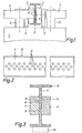
Figur 1 einen mittleren Querschnitt durch eine Fahrschiene, an der die Zuordnung einer Hängebahn schematisch gezeigt ist,Figur 2 eine Fahrschiene in einer seitlichen Ansicht undFigur 3 den Gegenstand derfigur 1 in einem mittleren Querschnitt, mit anliegenden Laufflächen der Reibräder.Figur 1 zeigt, wie eineHängebahn 1, beispielsweise eine Zugkatze, an einerFahrschiene 6 mit einem I-förmigen Profil aufgehängt ist. Sie läuft mit zweiLaufrollen 2 auf der Oberfläche des Schienenfußes. DieseLaufrollen 2 sind inLagerlaschen 3 geführt, welche gleichzeitig die anhängende Last auf diese Laufrollen übertragen. Die Laufrollen sind frei beweglich, d. h. sind nicht motorisch angetrieben. Der Antrieb erfolgt vielmehr mit Hilfe von zwei seitlichangeordneten Reibrädern 4, die um je einevertikale Antriebswelle 5 laufen. DieseWellen 5 werden über ein in der Zeichnung nicht dargestelltes Getriebe motorisch angetrieben, beispielsweise mit Hilfe eines Elektromotors.
- FIG. 1 shows a central cross section through a travel rail, on which the assignment of a monorail is shown schematically,
- Figure 2 shows a rail in a side view
- Figure 3 shows the subject of Figure 1 in a medium cross-section, with adjacent treads of the friction wheels.
- Figure 1 shows how a
monorail 1, for example a trolley, is suspended from arail 6 with an I-shaped profile. It runs with tworollers 2 on the surface of the rail foot. Theserollers 2 are guided inbearing plates 3, which simultaneously transfer the attached load to these rollers. The rollers are freely movable, ie they are not driven by a motor. Rather, the drive takes place with the aid of two laterally arrangedfriction wheels 4, each running around avertical drive shaft 5. Theseshafts 5 are motor-driven via a gear, not shown in the drawing, for example with the aid of an electric motor.
Erfindungsgemäß sind durch den Schienensteg 7 im Bereich der Anlageflächen der Reibräder 4 Löcher angeordnet. Diese führen beim Ausführungsbeispiel durch den Schienensteg hindurch, so daß sie also für beide Anlageflächen der Reibräder wirksam sind. Bei dem in figur 2 gezeigten Ausführungsbeispiel sind drei versetzt angeordnete Reihen solcher Löcher vorhanden. Je nach der Breite der Anlageflächen können auch mehr oder weniger Löcher vorgesehen sein. Weiterhin besteht die Möglichkeit, anstelle von kreisrunden Bohrungen, wie sie dort dargestellt sind, andere Querschnitte für die Löcher8 zu wählen. Auch die Größe der Löcher kann verschieden sein. Alternativ können die Löcher8 auch aus napfartigen Vertiefungen bestehen, die auf beiden Seiten in den Schienensteg 7 eingewalzt sind ; der Schienensteg wird hierdurch weniger geschwächt als bei durchgehenden Löchern.According to the invention, 4 holes are arranged through the
Figur 3 zeigt, daß die gegen den mittleren Schienensteg 7 gepreßten Laufflächen der Laufrollen 4 in diese Löcher8 hineingedrückt werden, wobei ein Teil der Laufflächenmasse 9 in die Löcher hineinragt. Hierdurch wird der Kraftschluß, d. h. die Haftung zwischen den von dem mittleren Schienensteg gebildeten Anlageflächen und der Lauffläche der Reibräder4 erheblich erhöht.FIG. 3 shows that the treads of the
Um die durch die Anbringung der Löcher 8 im mittleren Schienensteg bedingte Schwächung auszugleichen, können bedarfsweise unter dem Schienenfuß (wie dargestellt) oder auf dem Schienenkopf Verstärkungsschienen 10 angebracht, beispielsweise angeschweißt sein. Diese können einen massiven Querschnitt besitzen, ebenso lassen sich aber auch U-förmige Schienenteile o. dgl. anschweißen. Die Lauffläche der Reibräder 4 besteht in üblicher Weise aus Gummi oder Kunststoff mit einer Shore-Härte von etwa 90 bis 95°, vorzugsweise 92°.In order to compensate for the weakening caused by the provision of the
Claims (3)
Priority Applications (2)
| Application Number | Priority Date | Filing Date | Title |
|---|---|---|---|
| EP80200218A EP0035603B1 (en) | 1980-03-07 | 1980-03-07 | Rail with a double-t profile for suspension railways |
| AT80200218T ATE2555T1 (en) | 1980-03-07 | 1980-03-07 | TRAVEL RAIL WITH AN I-SHAPED PROFILE FOR OVERHEAD CONVEYOR CONVEYOR. |
Applications Claiming Priority (1)
| Application Number | Priority Date | Filing Date | Title |
|---|---|---|---|
| EP80200218A EP0035603B1 (en) | 1980-03-07 | 1980-03-07 | Rail with a double-t profile for suspension railways |
Publications (2)
| Publication Number | Publication Date |
|---|---|
| EP0035603A1 EP0035603A1 (en) | 1981-09-16 |
| EP0035603B1 true EP0035603B1 (en) | 1983-02-16 |
Family
ID=8186971
Family Applications (1)
| Application Number | Title | Priority Date | Filing Date |
|---|---|---|---|
| EP80200218A Expired EP0035603B1 (en) | 1980-03-07 | 1980-03-07 | Rail with a double-t profile for suspension railways |
Country Status (2)
| Country | Link |
|---|---|
| EP (1) | EP0035603B1 (en) |
| AT (1) | ATE2555T1 (en) |
Families Citing this family (3)
| Publication number | Priority date | Publication date | Assignee | Title |
|---|---|---|---|---|
| JPH0587003U (en) * | 1992-04-28 | 1993-11-22 | 大豊建設株式会社 | Guide rail |
| JP5189669B2 (en) | 2011-05-24 | 2013-04-24 | 田中貴金属工業株式会社 | Active metal brazing material |
| CN108301260A (en) * | 2018-04-02 | 2018-07-20 | 中唐空铁集团有限公司 | A kind of novel air rail road and application thereof |
Family Cites Families (5)
| Publication number | Priority date | Publication date | Assignee | Title |
|---|---|---|---|---|
| DE140056C (en) * | ||||
| US3884153A (en) * | 1971-12-23 | 1975-05-20 | Minoru Sugimoto | Monorail structure |
| DE2227304A1 (en) * | 1972-06-05 | 1973-12-20 | Fromme Foerderanlagen Gmbh | RUNNING RAIL WITH TOOTHED RACK FOR TROLLEYS |
| DE2354801B2 (en) * | 1973-11-02 | 1975-12-18 | Becorit Grubenausbau Gmbh, 4350 Recklinghausen | Runway for overhead monorails |
| DE2856164C2 (en) * | 1978-12-27 | 1984-08-02 | Mannesmann AG, 4000 Düsseldorf | Rail support, which is connected to a rail |
-
1980
- 1980-03-07 EP EP80200218A patent/EP0035603B1/en not_active Expired
- 1980-03-07 AT AT80200218T patent/ATE2555T1/en not_active IP Right Cessation
Also Published As
| Publication number | Publication date |
|---|---|
| EP0035603A1 (en) | 1981-09-16 |
| ATE2555T1 (en) | 1983-03-15 |
Similar Documents
| Publication | Publication Date | Title |
|---|---|---|
| DE2743316C3 (en) | Switch for two-lane overhead monorail vehicles | |
| DE2304958A1 (en) | CONVEYOR DEVICE WITH WHEELS RUNNING IN THE HALL AND WITH FORCED GUIDANCE | |
| EP0384223B1 (en) | Telpher line | |
| DE2836014C3 (en) | Rail bridging, in particular for an overhead conveyor used to transport people | |
| EP0304543B1 (en) | Overhead conveyor | |
| DE602004006304T2 (en) | DEVICE FOR LEADING AND ELECTRIC POWER SUPPLY OF A VEHICLE THROUGH A RINN IN THE GROUND | |
| EP0035603B1 (en) | Rail with a double-t profile for suspension railways | |
| DE2856164A1 (en) | RAIL FOR A VEHICLE | |
| DE3523187A1 (en) | Lift in buildings | |
| DE3721658A1 (en) | TRACK RAIL ARRANGEMENT OF A HANGING CONVEYOR SYSTEM | |
| DE2906203C3 (en) | Runway with an I-shaped profile for suspended tracks | |
| DE2916818A1 (en) | Inclined conveyor for shopping trolley - has manually released brake with smaller wheels on raised tracks to lift braked wheels in transit | |
| DE19723768C2 (en) | Means of transport for people and materials in underground mining and tunneling | |
| DE1815615A1 (en) | Track brake | |
| DE2529890C3 (en) | Cable guides, in particular pull cable guides, for cable cars | |
| DE19608643C1 (en) | Transportation trolley with running gear | |
| DE2728020C2 (en) | Rail-bound suspension railway or funicular, especially for underground operations | |
| DE2644582C3 (en) | Runway with associated drive unit | |
| DE202010012325U1 (en) | Modular system for conveyor technology | |
| DE3929301A1 (en) | Overhead conveyor with carriage - has C=section rail, and carriage is driven over horizontal regions by friction belt | |
| DE4401210C1 (en) | Electric monorail conveyor | |
| DE2254005C2 (en) | Bar track brake | |
| DE4302429A1 (en) | Rail for flanged wheels of motorised loading pallet | |
| DE102019128316A1 (en) | Electric monorail | |
| AT203413B (en) | Conveyor system for people and things |
Legal Events
| Date | Code | Title | Description |
|---|---|---|---|
| PUAI | Public reference made under article 153(3) epc to a published international application that has entered the european phase |
Free format text: ORIGINAL CODE: 0009012 |
|
| 17P | Request for examination filed |
Effective date: 19810227 |
|
| AK | Designated contracting states |
Designated state(s): AT BE CH FR GB IT LU NL SE |
|
| ITF | It: translation for a ep patent filed |
Owner name: STUDIO INGG. FISCHETTI & WEBER |
|
| GRAA | (expected) grant |
Free format text: ORIGINAL CODE: 0009210 |
|
| AK | Designated contracting states |
Designated state(s): AT BE CH FR GB IT LU NL SE |
|
| REF | Corresponds to: |
Ref document number: 2555 Country of ref document: AT Date of ref document: 19830315 Kind code of ref document: T |
|
| PGFP | Annual fee paid to national office [announced via postgrant information from national office to epo] |
Ref country code: FR Payment date: 19830314 Year of fee payment: 4 |
|
| PGFP | Annual fee paid to national office [announced via postgrant information from national office to epo] |
Ref country code: AT Payment date: 19830315 Year of fee payment: 4 |
|
| PG25 | Lapsed in a contracting state [announced via postgrant information from national office to epo] |
Ref country code: LU Free format text: LAPSE BECAUSE OF NON-PAYMENT OF DUE FEES Effective date: 19830331 |
|
| PGFP | Annual fee paid to national office [announced via postgrant information from national office to epo] |
Ref country code: SE Payment date: 19830331 Year of fee payment: 4 Ref country code: NL Payment date: 19830331 Year of fee payment: 4 |
|
| ET | Fr: translation filed | ||
| PGFP | Annual fee paid to national office [announced via postgrant information from national office to epo] |
Ref country code: LU Payment date: 19830415 Year of fee payment: 4 |
|
| PGFP | Annual fee paid to national office [announced via postgrant information from national office to epo] |
Ref country code: CH Payment date: 19830530 Year of fee payment: 4 |
|
| PGFP | Annual fee paid to national office [announced via postgrant information from national office to epo] |
Ref country code: BE Payment date: 19830630 Year of fee payment: 4 |
|
| PG25 | Lapsed in a contracting state [announced via postgrant information from national office to epo] |
Ref country code: AT Effective date: 19840307 |
|
| PG25 | Lapsed in a contracting state [announced via postgrant information from national office to epo] |
Ref country code: SE Effective date: 19840308 |
|
| PG25 | Lapsed in a contracting state [announced via postgrant information from national office to epo] |
Ref country code: CH Effective date: 19840331 Ref country code: BE Effective date: 19840331 |
|
| BERE | Be: lapsed |
Owner name: GLOGER JOSEF Effective date: 19840307 |
|
| PG25 | Lapsed in a contracting state [announced via postgrant information from national office to epo] |
Ref country code: NL Effective date: 19841001 |
|
| GBPC | Gb: european patent ceased through non-payment of renewal fee | ||
| NLV4 | Nl: lapsed or anulled due to non-payment of the annual fee | ||
| GBPC | Gb: european patent ceased through non-payment of renewal fee | ||
| PG25 | Lapsed in a contracting state [announced via postgrant information from national office to epo] |
Ref country code: FR Free format text: LAPSE BECAUSE OF NON-PAYMENT OF DUE FEES Effective date: 19841130 |
|
| REG | Reference to a national code |
Ref country code: CH Ref legal event code: PL |
|
| REG | Reference to a national code |
Ref country code: FR Ref legal event code: ST |
|
| PG25 | Lapsed in a contracting state [announced via postgrant information from national office to epo] |
Ref country code: GB Effective date: 19881118 |
|
| EUG | Se: european patent has lapsed |
Ref document number: 80200218.8 Effective date: 19850529 |
|
| PLBE | No opposition filed within time limit |
Free format text: ORIGINAL CODE: 0009261 |
|
| STAA | Information on the status of an ep patent application or granted ep patent |
Free format text: STATUS: NO OPPOSITION FILED WITHIN TIME LIMIT |