EP0035440B1 - Dispositif d'accord en hyperfréquences, du type à contacts glissants - Google Patents
Dispositif d'accord en hyperfréquences, du type à contacts glissants Download PDFInfo
- Publication number
- EP0035440B1 EP0035440B1 EP81400287A EP81400287A EP0035440B1 EP 0035440 B1 EP0035440 B1 EP 0035440B1 EP 81400287 A EP81400287 A EP 81400287A EP 81400287 A EP81400287 A EP 81400287A EP 0035440 B1 EP0035440 B1 EP 0035440B1
- Authority
- EP
- European Patent Office
- Prior art keywords
- cavity
- rod
- tuning device
- sliding
- laminae
- Prior art date
- Legal status (The legal status is an assumption and is not a legal conclusion. Google has not performed a legal analysis and makes no representation as to the accuracy of the status listed.)
- Expired
Links
- 229910052751 metal Inorganic materials 0.000 claims description 10
- 239000002184 metal Substances 0.000 claims description 10
- BQCADISMDOOEFD-UHFFFAOYSA-N Silver Chemical compound [Ag] BQCADISMDOOEFD-UHFFFAOYSA-N 0.000 description 12
- 229910052709 silver Inorganic materials 0.000 description 11
- 239000004332 silver Substances 0.000 description 11
- PCHJSUWPFVWCPO-UHFFFAOYSA-N gold Chemical compound [Au] PCHJSUWPFVWCPO-UHFFFAOYSA-N 0.000 description 5
- 229910052737 gold Inorganic materials 0.000 description 5
- 239000010931 gold Substances 0.000 description 5
- 239000004020 conductor Substances 0.000 description 4
- 230000005611 electricity Effects 0.000 description 3
- 229910001369 Brass Inorganic materials 0.000 description 2
- 229910000906 Bronze Inorganic materials 0.000 description 2
- 229910052790 beryllium Inorganic materials 0.000 description 2
- ATBAMAFKBVZNFJ-UHFFFAOYSA-N beryllium atom Chemical compound [Be] ATBAMAFKBVZNFJ-UHFFFAOYSA-N 0.000 description 2
- 239000010951 brass Substances 0.000 description 2
- 239000010974 bronze Substances 0.000 description 2
- KUNSUQLRTQLHQQ-UHFFFAOYSA-N copper tin Chemical compound [Cu].[Sn] KUNSUQLRTQLHQQ-UHFFFAOYSA-N 0.000 description 2
- 230000006866 deterioration Effects 0.000 description 2
- 238000005868 electrolysis reaction Methods 0.000 description 2
- 241000238876 Acari Species 0.000 description 1
- 229910045601 alloy Inorganic materials 0.000 description 1
- 239000000956 alloy Substances 0.000 description 1
- 238000005219 brazing Methods 0.000 description 1
- 239000011248 coating agent Substances 0.000 description 1
- 238000000576 coating method Methods 0.000 description 1
- 230000007547 defect Effects 0.000 description 1
- 230000001627 detrimental effect Effects 0.000 description 1
- 238000006073 displacement reaction Methods 0.000 description 1
- 238000010438 heat treatment Methods 0.000 description 1
- 239000000463 material Substances 0.000 description 1
- 238000003801 milling Methods 0.000 description 1
- 230000035515 penetration Effects 0.000 description 1
- 230000000750 progressive effect Effects 0.000 description 1
- 239000000523 sample Substances 0.000 description 1
- 238000007493 shaping process Methods 0.000 description 1
- 239000007787 solid Substances 0.000 description 1
Images
Classifications
-
- H—ELECTRICITY
- H01—ELECTRIC ELEMENTS
- H01P—WAVEGUIDES; RESONATORS, LINES, OR OTHER DEVICES OF THE WAVEGUIDE TYPE
- H01P7/00—Resonators of the waveguide type
- H01P7/04—Coaxial resonators
Definitions
- the present invention relates to a microwave tuning device comprising a part fixed relative to the wall of a cavity and a movable part sliding inside the fixed part so as to be able to penetrate more or less deeply into the cavity; good quality electrical contact between the fixed part and the moving part must ensure the passage of surface currents between these two parts.
- Such devices are known, for example from patent US 25 56 607, in which elastic blades integral with one of the parts ensure sliding contact with the other part. These blades are made of materials with good elasticity but are therefore hard, fragile, abrasive and poorly conduct electricity. To remedy these defects, it is known to cover these elastic strips with a deposit of silver or gold produced by electrolysis, which constitutes a good conductor of the microwave currents which are surface currents. Since the moving part, for reasons of mechanical rigidity, must be made of a metal whose hardness is greater than that of silver or gold, the repeated movements of the moving part inside the fixed part, due to friction, lead to a rapid deterioration of the surface condition, that is to say the deposit of silver or gold.
- the object of the present invention is to ensure good electrical contact between the fixed part and the mobile part of the device, even when the mobile part is moving.
- a microwave tuning device as described in claim 1 attached, achieves this goal. It is a tuning device comprising a movable cylindrical rod having a sliding surface and a hollow cylindrical part, fixed to a wall of a cavity, which it crosses, and completed, towards its end situated in the cavity, by n elastic parts (n integer at least equal to 2) and inside which the rod slides, crossing it right through to penetrate an adjustable length into the cavity, the elastic parts pressing on the surface sliding contacts;
- n longitudinal slots are formed in the end of the cylindrical part located in the cavity and in that the elastic parts comprise: the n blades of the cylindrical part comprised between the n slots and n added parts constituting jaws, of metal which is a good conductor of electricity, associated respectively with the n blades and forming the contacts.
- the advantages provided by the tuning device according to the invention mainly consist in a better functioning and a longer life of the equipment.
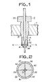
- Fig. 1 is a partial view, in section, of an “frequency agile” filter.
- Fig. 1 shows the wall 1 of a cavity. This wall is pierced with a cylindrical hole, 11 mm in diameter, into which is fitted a tuning device; this tuning device comprises a hollow cylindrical part 2, forming a clamp; inside this clamp slides a cylindrical rod, solid, 3, made of brass.
- the clamp 2 has a cylindrical head, 20, with an outside diameter of 20 mm, outside the cavity, a middle part 21 of the diameter of the hole drilled in the wall of the cavity and an end part 22 consisting of a cylinder with an outside diameter of 9 mm. . While the head 20 and the middle part 21 have a large wall thickness, the end part 22 is a hollow cylinder with a thin wall, which is split longitudinally over a length AB, according to four parallel slots, at 90 ° from each other ; the clamp 2 is made of beryllium bronze and, thanks to a treatment which will be described later, the four blades determined by the four slots are made elastic.
- inserts such as 40, 41, are interposed between the elastic blades and the rod 3; these inserts, produced in silver, probes integral with the elastic blades and come into contact with the rod 3.
- the clamp 2 is stuffed as follows.
- a beryllium bronze blank is produced which is taken up mechanically to achieve the desired dimensions, in particular as regards the outside diameter of the middle part.
- a silver ring is made integral, by brazing, with the free end of the terminal part 22 of the clamp 2.
- the terminal part is then sawn using a very fine milling cutter giving a slot width of 3/10 8 millimeter.
- a conformator constituted by a cylindrical centering axis with a diameter of 1.6 mm, is introduced into the hole of the split ring where the rod 3 will slide. It should be noted that the diameter of this conformator is slightly less than the diameter of the part of the rod 3 which will slide in the clamp 2 so as to ensure, thereafter, a good tightening of the rod between the ends of the clamp.
- a strapping made using a metal strip, keeps the ends of the clamp 2 in contact with the shaping device.
- the assembly constituted by the clamp 2, the conformator and the strapping band is introduced for two hours into an enclosure at 320 ° C; this conventional heat treatment is intended to give the blades of the clamp 2 the desired elasticity.
- the forceps are then covered, by electrolysis, with a silver deposit with a thickness of 7 microns.
- the clamp does not risk, by rapid wear at the level of the sliding contacts, to cause the disabling of the tuning device.
- the admissible wear at the level of the contacts is no longer a few microns as with conventional devices where, under the few microns of thickness of the electrolytic deposit of silver, wear shows at the end of the clamp in contact with the rod, a bad conductive metal; this allowable wear is now a few tenths of a millimeter.
- the wear of the silver of the added parts, such as 40, 41, on the brass of the rod 3 performs a lapping of the tuning device and therefore improves its operation; on the contrary in conventional devices having no attachments, the wear of the silver, which is only there in the form of a thin electrolytic deposit, tends to form chips which are detrimental to the proper functioning of the device.
- Fig. 2 is a sectional view along XX (see fig. 1) of the tuning device. This view shows the movable rod 3 which, by the I of the four stic blades, marked 25 to 28, constituting the end 22 of the clamp, is clamped between the jaws of the clamp. These jaws are formed by the four sections of the split ring which were discussed during the description of FIG. 1; they are designated by the references 40 to 43 in FIG. 2.
- the insert (40, 41 in FIG. 1), making contact can be produced not only in silver but in any other metal or alloy which is a good conductor of electricity and relatively malleable so as to be able to wearing out, matching the shape of the sliding surface against which it comes into contact; this is the break-in that was discussed earlier.
- this insert is of dimensions clearly greater than the surface of the sliding contact which it must provide, it is possible to produce it by assembling two metal parts: a metal part which is good conductor of surface currents and relatively malleable, at the place of sliding contact, and another metal part for which the choice of metal no longer has to be guided by considerations of electrical conductivity.
Landscapes
- Control Of Motors That Do Not Use Commutators (AREA)
- Arc-Extinguishing Devices That Are Switches (AREA)
- Connections Effected By Soldering, Adhesion, Or Permanent Deformation (AREA)
Applications Claiming Priority (2)
| Application Number | Priority Date | Filing Date | Title |
|---|---|---|---|
| FR8004949A FR2477782A1 (fr) | 1980-03-05 | 1980-03-05 | Dispositif d'accord en hyperfrequences, du type a contacts glissants, et filtre comportant un tel dispositif |
| FR8004949 | 1980-03-05 |
Publications (2)
| Publication Number | Publication Date |
|---|---|
| EP0035440A1 EP0035440A1 (fr) | 1981-09-09 |
| EP0035440B1 true EP0035440B1 (fr) | 1984-05-16 |
Family
ID=9239343
Family Applications (1)
| Application Number | Title | Priority Date | Filing Date |
|---|---|---|---|
| EP81400287A Expired EP0035440B1 (fr) | 1980-03-05 | 1981-02-24 | Dispositif d'accord en hyperfréquences, du type à contacts glissants |
Country Status (5)
| Country | Link |
|---|---|
| US (1) | US4376923A (OSRAM) |
| EP (1) | EP0035440B1 (OSRAM) |
| JP (1) | JPS56136002A (OSRAM) |
| DE (1) | DE3163570D1 (OSRAM) |
| FR (1) | FR2477782A1 (OSRAM) |
Families Citing this family (7)
| Publication number | Priority date | Publication date | Assignee | Title |
|---|---|---|---|---|
| GB8323143D0 (en) * | 1983-08-27 | 1983-09-28 | Oxley R F | Tuning screw |
| FI89115C (fi) * | 1991-09-18 | 1993-08-10 | Lk Products Oy | Foerfarande foer faestandet av en resonatorstav mot ett hoegfrekvensfilters vaegg och hoegfrekvensfilter |
| GB2308235B (en) * | 1995-12-12 | 1999-11-24 | Eev Ltd | High frequency apparatus |
| DE19707153A1 (de) * | 1997-02-22 | 1998-08-27 | Philips Patentverwaltung | Mikrowellen-Bauelement |
| US6104263A (en) * | 1997-05-28 | 2000-08-15 | Hewlett-Packard Company | Capacitive tuning screw having a compressible tip |
| US8269582B2 (en) * | 2009-10-30 | 2012-09-18 | Alcatel Lucent | Tuning element assembly and method for RF components |
| KR102422720B1 (ko) * | 2017-05-02 | 2022-07-20 | 주식회사 케이엠더블유 | 캐비티 타입의 무선 주파수 필터 |
Citations (3)
| Publication number | Priority date | Publication date | Assignee | Title |
|---|---|---|---|---|
| US2556607A (en) * | 1946-07-27 | 1951-06-12 | Hazeltine Research Inc | Wave-signal translating arrangement |
| US2561727A (en) * | 1943-07-07 | 1951-07-24 | Harold G Cooper | Tuning of electrical resonators |
| US2790151A (en) * | 1952-01-05 | 1957-04-23 | Henry J Riblet | Temperature compensated cavity resonator |
Family Cites Families (1)
| Publication number | Priority date | Publication date | Assignee | Title |
|---|---|---|---|---|
| DE1280996B (de) * | 1967-07-14 | 1968-10-24 | Telefunken Patent | Abstimmvorrichtung fuer den Hohlraum eines Mikrowellenbauteils |
-
1980
- 1980-03-05 FR FR8004949A patent/FR2477782A1/fr active Granted
-
1981
- 1981-02-24 EP EP81400287A patent/EP0035440B1/fr not_active Expired
- 1981-02-24 DE DE8181400287T patent/DE3163570D1/de not_active Expired
- 1981-03-04 US US06/240,286 patent/US4376923A/en not_active Expired - Fee Related
- 1981-03-04 JP JP3108381A patent/JPS56136002A/ja active Granted
Patent Citations (3)
| Publication number | Priority date | Publication date | Assignee | Title |
|---|---|---|---|---|
| US2561727A (en) * | 1943-07-07 | 1951-07-24 | Harold G Cooper | Tuning of electrical resonators |
| US2556607A (en) * | 1946-07-27 | 1951-06-12 | Hazeltine Research Inc | Wave-signal translating arrangement |
| US2790151A (en) * | 1952-01-05 | 1957-04-23 | Henry J Riblet | Temperature compensated cavity resonator |
Also Published As
| Publication number | Publication date |
|---|---|
| JPS6153887B2 (OSRAM) | 1986-11-19 |
| FR2477782B1 (OSRAM) | 1983-12-23 |
| EP0035440A1 (fr) | 1981-09-09 |
| JPS56136002A (en) | 1981-10-23 |
| DE3163570D1 (en) | 1984-06-20 |
| FR2477782A1 (fr) | 1981-09-11 |
| US4376923A (en) | 1983-03-15 |
Similar Documents
| Publication | Publication Date | Title |
|---|---|---|
| EP0148088B1 (fr) | Joint d'étanchéité métallique flexible comportant des parties saillantes consommables | |
| EP0662736B1 (fr) | Collecteur électrique tournant à balais multibrins | |
| EP0035440B1 (fr) | Dispositif d'accord en hyperfréquences, du type à contacts glissants | |
| EP1202299B1 (fr) | Dispositif d'accumulation d'énergie électrique constitué par enroulement de rubans superposés et procédé de fabrication | |
| EP1586122B1 (fr) | Module photovoltaique comportant des bornes de connexion avec l'exterieur | |
| WO1992004746A1 (fr) | Connecteur femelle a contacts double-lame | |
| CA2138358A1 (fr) | Plaque d'electrode a support de type mousse metallique pour generateur electrochimique et procede pour fabriquer une telle plaque d'electrode | |
| FR2604026A1 (fr) | Disjoncteur possedant une structure perfectionnee d'extinction d'arc | |
| EP0241331A1 (fr) | Procédé pour la réalisation de motifs électriquement conducteurs sur une surface non développable d'un substrat isolant et dispositif obtenu | |
| EP0068919A1 (fr) | Résonateur hyperfréquence du type condensateur variable à diélectrique | |
| FR3070799A1 (fr) | Dispositif de connexion de deux elements conducteurs d'un rail d'alimentation | |
| CA1080795A (fr) | Eclateur declenche dans un gaz | |
| WO2005029649A2 (fr) | Dispositif de connexion pour panneaux conducteurs d’electricite | |
| EP0038243A1 (fr) | Profilé métallique pour la réalisation d'un élément conducteur, procédé de réalisation de cet élément conducteur et élément conducteur réalisé par ce procédé | |
| FR2479579A1 (fr) | Dispositif de fixation et de prise de contact electrique d'une pile dans une montre | |
| EP0534846A1 (fr) | Système de connexion électrique pour câble plat | |
| FR2717012A1 (fr) | Machine dynamoélectrique comportant un balai possédant un noyau oblique. | |
| FR2946468A1 (fr) | Dispositif de liaison entre un connecteur electrique et un cable electrique coaxial blinde et connecteur electrique correspondant | |
| EP0117804A1 (fr) | Procédé de fabrication d'une cavité hyperfréquence, et cavité obtenue par ce procédé | |
| FR2918505A1 (fr) | Attenuateur coaxial | |
| FR2690367A1 (fr) | Dispositif de positionnement d'un outil ou d'une pièce sur une machine-outil. | |
| FR2504318A1 (fr) | Lame conductrice pour collecteurs de machines electriques tournantes et son procede de fabrication | |
| EP0531222A1 (fr) | Procédé de réalisation, par découpe dans un ruban, d'une lame porte-contacts d'interrupteur et lame réalisée selon le procédé | |
| WO1984000442A1 (fr) | Interrupteur electrique a ressort de contact prearme | |
| FR2480653A1 (fr) | Organe de rasage, et procede et appareil de soudage d'une lame sur un support |
Legal Events
| Date | Code | Title | Description |
|---|---|---|---|
| PUAI | Public reference made under article 153(3) epc to a published international application that has entered the european phase |
Free format text: ORIGINAL CODE: 0009012 |
|
| AK | Designated contracting states |
Designated state(s): DE GB IT |
|
| 17P | Request for examination filed |
Effective date: 19820206 |
|
| ITF | It: translation for a ep patent filed | ||
| GRAA | (expected) grant |
Free format text: ORIGINAL CODE: 0009210 |
|
| AK | Designated contracting states |
Designated state(s): DE GB IT |
|
| REF | Corresponds to: |
Ref document number: 3163570 Country of ref document: DE Date of ref document: 19840620 |
|
| PLBE | No opposition filed within time limit |
Free format text: ORIGINAL CODE: 0009261 |
|
| STAA | Information on the status of an ep patent application or granted ep patent |
Free format text: STATUS: NO OPPOSITION FILED WITHIN TIME LIMIT |
|
| 26N | No opposition filed | ||
| PGFP | Annual fee paid to national office [announced via postgrant information from national office to epo] |
Ref country code: GB Payment date: 19891231 Year of fee payment: 10 |
|
| PGFP | Annual fee paid to national office [announced via postgrant information from national office to epo] |
Ref country code: DE Payment date: 19900222 Year of fee payment: 10 |
|
| ITTA | It: last paid annual fee | ||
| PG25 | Lapsed in a contracting state [announced via postgrant information from national office to epo] |
Ref country code: GB Effective date: 19910224 |
|
| GBPC | Gb: european patent ceased through non-payment of renewal fee | ||
| PG25 | Lapsed in a contracting state [announced via postgrant information from national office to epo] |
Ref country code: DE Effective date: 19911101 |