EP0035425B1 - Procédé de fabrication de transducteurs électromécaniques utilisant au moins un film en polymère, et dispositif destiné à la mise en oeuvre de ce procédé - Google Patents
Procédé de fabrication de transducteurs électromécaniques utilisant au moins un film en polymère, et dispositif destiné à la mise en oeuvre de ce procédé Download PDFInfo
- Publication number
- EP0035425B1 EP0035425B1 EP81400239A EP81400239A EP0035425B1 EP 0035425 B1 EP0035425 B1 EP 0035425B1 EP 81400239 A EP81400239 A EP 81400239A EP 81400239 A EP81400239 A EP 81400239A EP 0035425 B1 EP0035425 B1 EP 0035425B1
- Authority
- EP
- European Patent Office
- Prior art keywords
- die
- shaping
- face
- metallizations
- faces
- Prior art date
- Legal status (The legal status is an assumption and is not a legal conclusion. Google has not performed a legal analysis and makes no representation as to the accuracy of the status listed.)
- Expired
Links
Images

Classifications
-
- H—ELECTRICITY
- H04—ELECTRIC COMMUNICATION TECHNIQUE
- H04R—LOUDSPEAKERS, MICROPHONES, GRAMOPHONE PICK-UPS OR LIKE ACOUSTIC ELECTROMECHANICAL TRANSDUCERS; ELECTRIC HEARING AIDS; PUBLIC ADDRESS SYSTEMS
- H04R17/00—Piezoelectric transducers; Electrostrictive transducers
- H04R17/005—Piezoelectric transducers; Electrostrictive transducers using a piezoelectric polymer
-
- H—ELECTRICITY
- H10—SEMICONDUCTOR DEVICES; ELECTRIC SOLID-STATE DEVICES NOT OTHERWISE PROVIDED FOR
- H10N—ELECTRIC SOLID-STATE DEVICES NOT OTHERWISE PROVIDED FOR
- H10N30/00—Piezoelectric or electrostrictive devices
- H10N30/01—Manufacture or treatment
- H10N30/04—Treatments to modify a piezoelectric or electrostrictive property, e.g. polarisation characteristics, vibration characteristics or mode tuning
- H10N30/045—Treatments to modify a piezoelectric or electrostrictive property, e.g. polarisation characteristics, vibration characteristics or mode tuning by polarising
-
- H—ELECTRICITY
- H10—SEMICONDUCTOR DEVICES; ELECTRIC SOLID-STATE DEVICES NOT OTHERWISE PROVIDED FOR
- H10N—ELECTRIC SOLID-STATE DEVICES NOT OTHERWISE PROVIDED FOR
- H10N30/00—Piezoelectric or electrostrictive devices
- H10N30/01—Manufacture or treatment
- H10N30/09—Forming piezoelectric or electrostrictive materials
- H10N30/098—Forming organic materials
-
- Y—GENERAL TAGGING OF NEW TECHNOLOGICAL DEVELOPMENTS; GENERAL TAGGING OF CROSS-SECTIONAL TECHNOLOGIES SPANNING OVER SEVERAL SECTIONS OF THE IPC; TECHNICAL SUBJECTS COVERED BY FORMER USPC CROSS-REFERENCE ART COLLECTIONS [XRACs] AND DIGESTS
- Y10—TECHNICAL SUBJECTS COVERED BY FORMER USPC
- Y10S—TECHNICAL SUBJECTS COVERED BY FORMER USPC CROSS-REFERENCE ART COLLECTIONS [XRACs] AND DIGESTS
- Y10S310/00—Electrical generator or motor structure
- Y10S310/80—Piezoelectric polymers, e.g. PVDF
-
- Y—GENERAL TAGGING OF NEW TECHNOLOGICAL DEVELOPMENTS; GENERAL TAGGING OF CROSS-SECTIONAL TECHNOLOGIES SPANNING OVER SEVERAL SECTIONS OF THE IPC; TECHNICAL SUBJECTS COVERED BY FORMER USPC CROSS-REFERENCE ART COLLECTIONS [XRACs] AND DIGESTS
- Y10—TECHNICAL SUBJECTS COVERED BY FORMER USPC
- Y10T—TECHNICAL SUBJECTS COVERED BY FORMER US CLASSIFICATION
- Y10T29/00—Metal working
- Y10T29/42—Piezoelectric device making
Definitions
- the invention relates to the manufacture of transducers such as microphone, earphone, loudspeaker, ultrasound probe, hydrophone, etc. which comprise at least one active element comprising a polymer film provided with electrodes.
- Document US-A-3 816 774 describes transducers made up of a bimorph structure comprising two polymer films adhering to each other. This structure is shaped by thermoforming between two molds equipped with electrodes. These electrodes cooperate with metallizations protected by the structure to obtain the electrical polarization of the films which gives them the desired piezoelectric properties.
- the invention relates more particularly to transducers in which one or more polymer films are shaped by thermoforming and / or electroforming, in order to constitute a self-supporting structure such as a dome, cone, etc.
- the complex shape of the structure means that the patterns of the mask are projected with deformations or that, as a result of the existence of shadow zones, the masking introduces discontinuities of unacceptable electrodes.
- the invention proposes to format a flat film already coated with its metallizations.
- the shaping then brings together the combined actions of stretching, heating and electrical polarization, while the prior laying of metallizations on the planar structure to be shaped simplifies the precise delimitation of the electrodes.
- it is necessary that the stretching of the metallizations does not generate any solution of continuity of the electrodes and of their connections and that the residual voltages after shaping do not create mechanical instability of the self-supporting structure. .
- the subject of the invention is a method of manufacturing electromechanical transducers using at least one polymer film which is subjected to shaping such that the structure obtained is self-supporting and not developable, this structure being provided with electrodes on its two faces.
- said method consisting in first providing the two faces of the planar structure comprising this film with similar metallizations and in shaping this structure by applying, during a thermal process comprising a heating step followed by a cooling step, a mechanical stress on the faces of the structure, and a bias voltage to metallizations, said method being characterized in that said mechanical stress consists in stretching of the faces of the structure and results in a permanent increase in the surface of the metallizations carried by this structure, which are intended to form these electrodes.
- the invention also relates to a device intended for the implementation of this manufacturing process and comprising a punch associated with peripheral clamping means of the polymer structure delimiting above this punch the flat area to be brought into shape, characterized in that the electrical polarization of the polymer structure is ensured by electrical connections established during forming between the metallizations contained in this flat area, the punch and the peripheral clamping means.
- the shaping method according to the invention applies to any lamellar structure comprising at least one polymer film framed by two metal deposits.
- a linear and reversible electromechanical transducer effect can be induced by creating a permanent electrical anisotropy in the polymer film. This anisotropy can be obtained by creating a excess charge or by dipolar orientation of the macromolecular chains in the presence of a strong transverse electric field.
- the dipolar orientation technique makes it possible to induce a piezoelectric effect in polar homopolymers such as polyvinylidene fluoride (PVF z ), polyvinyl fluoride (PVF) and polyvinyl chloride (PVC) as well as in polar copolymers such as the copolymer of polyvinylidene fluoride and polyethylene tetrafluoride (PVF 2 - PTFE).
- polar homopolymers such as polyvinylidene fluoride (PVF z ), polyvinyl fluoride (PVF) and polyvinyl chloride (PVC)
- polar copolymers such as the copolymer of polyvinylidene fluoride and polyethylene tetrafluoride (PVF 2 - PTFE).
- Bimorphic structures can be produced by making two films adhere to each other so as to obtain a flexural deformation.
- the apparatus illustrated in Figure 1 is used to stretch a metallized polymer film on its two faces to highlight the ability of metallizations to retain their conductive qualities and their adhesion during a significant plastic deformation.
- the apparatus of FIG. 1 comprises a prismatic bench 1 of axis XX carrying a fixed support 4 electrically insulated by a sole 14.
- a mobile support 2 slides along the bench 1.
- Two clamping plates 3 and 5 cooperate with the supports 2 and 4, in order to forcefully pinch the ends of a tensile test piece of rectangular shape.
- This consists of a film of polymer material 7 to the faces of which metallizations 6 and 8 are similar.
- An ohmmeter 9 is connected between the conductive masses 2 and 4 so as to measure the electrical resistance of the metallization 8.
- the structure 6, 7, 8 is simply tensioned and the ohmmeter 9 provides the measurement R of the initial resistance of the layer 8 between two parallel contact lines distant from 1.
- the supports 2 and 4 of the spacing forces F so as to create an elongation ⁇ I to which corresponds an increase ⁇ R of the resistance measured.
- the corresponding increases ⁇ R of the electrical resistance of the metallization 8 are noted.
- the relative elongations have been plotted on a diagram. and the relative strength increases for two different compositions of the metal layers 6 and 8.
- the curve 11 relates the variation in resistance relative elongation in the case of metallizations formed by the evaporation on each face of the film 7 of a layer of chromium of 30 ⁇ followed by the evaporation of a layer of gold of 500 to 600 A.
- the curve 12 in dotted lines relates to the case of metallizations formed on each face of the film 7 by thermal evaporation of an aluminum layer of 1500 ⁇ thick.
- the slope of the curves 11 and 12 follows the straight line 10 passing through the points and In this stretching range, it can be considered that the variation in resistance of the metallization results from the reversible necking of the passage section of the measurement current and from the elastic elongation of the path taken by this current.
- the curves 11 and 12 separate from the straight line 10 by bending upwards, which indicates a faster growth of in terms of . This faster growth can be explained by the increase in resistivity Q which characterizes the behavior of thin films and by the formation of micro-cracks between the elementary grains constituting the metallic layer.
- the film 7 has a thickness of 25 ⁇ m and the entire apparatus is placed in a thermostatic enclosure brought to the temperature of 100 ° C. This temperature is that at which the PVF 2 is usually formed. What is remarkable is that the tensile test can continue beyond a relative elongation of 100% without being observed an abrupt interruption of the measurement current. On the other hand, the adhesion of the metallizations remains good and the stretched structure retains its shape after unloading.
- the tensile test relates to an undirectional stretch along the axis XX.
- the stretching of the structure of FIG. 1 was carried out in two stages first along the axis XX and then along the axis YY. Between the two tensile tests, the structure 6, 7, 8 was dismantled and tightened after a 90 ° rotation in its plane.
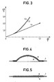
- Figure 3 shows on the same scale as in Figure 2 the law of variation of the relative increase in resistance as a function of proportional elongation .
- Curve 12 corresponds to the first stretch in the direction XX and the dotted curve 13 relates to the second tensile test along the YY axis. These curves are superimposable apart from experimental errors.
- a shaping comprising a biaxial stretching can be envisaged in a very wide range of proportional elongations.
- the increase in electrical resistance remains moderate and is of no consequence in the context of transducer systems implementing induced electric fields in dielectric materials.
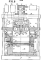
- FIG. 4 represents a piezoelectric transducer element in the form of a spherical cap which comprises a thin film of polymer 7 provided with metallizations 6 and 8.
- FIG. 5 shows the structure from which one has started to form the transducer element of FIG. 4.
- the dielectric disc 7 overflows the metallizations 6 and 8.
- the polymer film is subjected to an electric polarization field whose intensity is l 'order of 1 MV / cm.
- the voltage to be applied between metallizations 6 and 8 can reach several thousand volts for a prohibition of only 25! Lm.
- the height of the spherical cap is 15 mm for a base diameter of 70 mm.
- the flat metallizations of Figure 5 have a slightly larger diameter to allow peripheral clamping with contact.
- the average biaxial stretch is in this case close to 11%, that is to say much less than that which the metallizations can withstand before rupture or detachment.
- Figure 6 shows a partial section.
- This device comprises a base 15 connected to an upper deck 16 by columns 17.
- a sliding crown 18 can be locked on the columns 17 at a suitable height from the base 15.
- the upper deck 16 has a central bore through which the piston 19 passes.
- a hydraulic cylinder 20 provided with an intake manifold 21.
- the lower end of the piston 19 is in the form of a hollow cylindrical body 22 on the underside of which is mounted a punch 23.
- the punch 23 is fixed to the hollow body 22 by a bolt 24 having a central bore.
- the punch 23 is thermally insulated from the hollow body 22 by a seal 25 and to avoid a thermal bridge, the bolt 24 is made of polyethylene tetrafluoride.
- the underside of the hollow body 22 is provided with two end pieces 26 and 27 which communicate with an annular chamber 28 by means of two holes made in the thermal seal 25.
- the punch 23 is made of metal which is a good conductor of heat and its polished underside 29 follows the non-developable shape which it is desired to impose on the planar structure 6, 7, 8
- a thermocouple 30 is used to measure the temperature of the punch 23; it is connected to a millivoltmeter 31 by electrical connections passing through the central bore of the bolt 24.
- the heating of the punch 23 is obtained for example by the circulation of a heat transfer fluid such as hot air in the annular chamber 28
- a heat source 32 is connected by pipes 33 and 34 to the nozzles 26 and 27.
- a bias voltage generator 35 has its ground terminal connected to the hollow body 20 and consequently to the punch 23.
- the peripheral clamping means of the structure 6, 7, 8 to be shaped include an insulating sole 36 which rests on the base 15.
- the sole 36 carries a metal pot 37 with a cylindrical side wall which encloses a cavity 38 sufficiently deep to receive the lower active part of the shank 23.
- the inner rim of the side wall of the pot 37 is provided with a metal ring 39, the upper face of which is machined so as to present several concentric grooves with rectangular profile.
- the grooves of the ring 39 have a pitch of 0.5 mm, a width of 0.3 mm and a depth of 0.2 mm.
- the outer rim of the cylindrical pot wall 37 has undergone a relief in which a retaining ring 40 of the structure 6, 7, 8 takes place.
- This retaining ring 40 is made of insulating material and is used to hold the folded edges of the structure 6, 7, 8.
- the upper face of the ring 40 has a circular centering groove 41.
- a pinching ring 42 is provided above the pot 37 .
- This crown 42 is biased towards the crown 18 by means of springs 43. It is internally lined with an insulating jacket 44 which has a rim 45 completely covering the underside of the crown 42.
- the inner rim of the shirt 44 is provided a conductive ring 46 of the same type as the ring 39.
- the striated rings 46 and 39 act as clamping jaws and connection socket for metallizations 8 and 6 of the structure to be shaped.
- the pinching of the structure to be shaped results from the thrust exerted by jacks 47 housed on the ring 18.
- the jacks 47 tend to bring the ring 42 closer to the pot 37. Centering is ensured by a circular boss 48 which engages in the circular groove 41.
- the ring 46 is electrically connected to the generator 35 by an electrical connection 49.
- the ring 39 is electrically connected to the generator 35 by an electrical connection 50, via the metal pot 37. It is planned to subject the cavity 38 and the underside of the structure to be shaped to hydrostatic back pressure. For this purpose.
- the pot 37 is provided with an end piece 51.
- a generator 52 of pressurized fluids supplies the end pieces 51, 21 and the jacks 47 with appropriate pipes.
- the crown 18, the casing 44 and the cavity 38 form a well in which the punch can be lowered sufficiently to form the structure 6, 7, 8 completely.
- the orifice 51 is open to the open air.
- the crown 18 can be lowered and blocked on the columns 17.
- By actuating the jacks 47 an energetic pinching of the structure 6, 7, 8 between the jaws 39 and 46 is caused, which establishes the electrical connections with the metallizations 8 and 6.
- the film 7 heats up thanks to the heat given off by the punch.
- the bias voltage is applied to the connection 50 and the forming is started by a slow descent of the punch 23.
- the descent is 2 mm / min. This descent is interrupted when the punch marries by its curved face the entire extent of the structure to be formed.
- the bias voltage is maintained for approximately 20 minutes and having cut it, the punch is cooled to bring the thermoformed structure to room temperature. It only remains to raise the punch and release the thermoformed structure by removing the peripheral pinching and removing the retaining ring 40.
- the shaping results from thermoforming by the punch and electroforming from the tension of polarization.
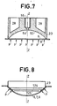
- FIG. 7 we can see a sectional view of a punch 23 for performing the forming of the structure under the action of the hydrostatic thrust p.
- the lower face 53 of the punch 23 is concave and the pole is occupied by a tiny orifice 54 which allows the air enclosed between the film to be shaped and the concave face 53 to escape.
- the operation is the same as before until contact with the punch and the metallization 6.
- hydrostatic pressure supplied by the source 52 is acted in the cavity 38.
- the fluid used can be liquid or gaseous, its role being to make the structure of FIG. 5 conform to the concave shape of the face 53.
- the film is still heated by a heat transfer fluid circulating in the annular chamber 28 of the punch, but it is also possible to place a radiant heat source in the cavity 38.
- the polarization field is applied and the forming fluid is injected by the nozzle 51 under a pressure which can reach a few hundreds of thousands of Pascal. After the heating time of twenty minutes, the film is cooled under an electric field and the thrust p can be reduced to zero.
- a variant of this process consists in letting the orifice 51 communicate in the open air and in sucking through the orifice 55 the air trapped between the film and the face 53.
- the thrust p is limited to the value of 100,000 Pascal , which is enough to form the dome described in Figure 4.
- FIG. 8 shows two peripheral depressions 124 and 125.
- the general shape is acquired by punching. After this insertion, the film is brought to follow the shape of the concave parts 124 and 125 under the action of a hydrostatic thrust exerted in the cavity 38 by a liquid or gaseous fluid.
- the punch at a constant temperature.
- the upper metallization of the structure to be thermoformed is connected to the ground of the generator 35 by a connection 49 which makes it possible to apply the bias voltage to the polymer film regardless of whether the punch is in contact with the structure to get in shape.
- the cavity 38 is placed under vacuum and the punch is raised, which ensures cooling under an electric field.
- the acquired shape is preserved thanks to the depression and the punch film separation is facilitated. This separation does not cut the polarization electric field during the cooling of the shaped structure.
- the preparation of the structure of FIG. 5 with a view to shaping consists in forming metallizations on each face of a polymer film. These metallizations can be obtained by thermal evaporation under vacuum in two stages. The temperature conditions are different, because the second deposit is made in presence of the first which behaves like a mirror. As a result, the forming properties are not exactly the same for both sides of the polymer film.
- a strip of polymer film can be used introduced between the jaws 39 and 46.
- the jaws are tightened and the structure is cut without the need to pre-cut the flat structures and to maintain them one by one by means of the ring 40.
- the strip received by masking metallizations which follow one another at constant pitch.
- Each shaped structure can keep with the strip connecting points which facilitate its unloading and which are subsequently broken.
- continuous and automated manufacturing can be envisaged.
- the heating means of the structure can be reinforced or replaced by providing, for example, to drown heating resistances in the wall of the pot 37 or of the punch 23.
- the cavity 38 can be filled by means of a heat-transfer liquid or heated by another fluid. This filling liquid can possibly establish an electrical connection with the structure if it is made conductive.
Landscapes
- Engineering & Computer Science (AREA)
- Manufacturing & Machinery (AREA)
- Physics & Mathematics (AREA)
- Acoustics & Sound (AREA)
- Signal Processing (AREA)
- Electrostatic, Electromagnetic, Magneto- Strictive, And Variable-Resistance Transducers (AREA)
- Transducers For Ultrasonic Waves (AREA)
- Moulds For Moulding Plastics Or The Like (AREA)
- Fixed Capacitors And Capacitor Manufacturing Machines (AREA)
Applications Claiming Priority (2)
| Application Number | Priority Date | Filing Date | Title |
|---|---|---|---|
| FR8004832A FR2477823A1 (fr) | 1980-03-04 | 1980-03-04 | Procede de fabrication de transducteurs electromecaniques utilisant au moins un film en polymere et dispositif destine a la mise en oeuvre de ce procede |
| FR8004832 | 1980-03-04 |
Publications (2)
| Publication Number | Publication Date |
|---|---|
| EP0035425A1 EP0035425A1 (fr) | 1981-09-09 |
| EP0035425B1 true EP0035425B1 (fr) | 1984-04-25 |
Family
ID=9239296
Family Applications (1)
| Application Number | Title | Priority Date | Filing Date |
|---|---|---|---|
| EP81400239A Expired EP0035425B1 (fr) | 1980-03-04 | 1981-02-17 | Procédé de fabrication de transducteurs électromécaniques utilisant au moins un film en polymère, et dispositif destiné à la mise en oeuvre de ce procédé |
Country Status (8)
| Country | Link |
|---|---|
| US (1) | US4403382A (enExample) |
| EP (1) | EP0035425B1 (enExample) |
| JP (1) | JPS56135920A (enExample) |
| CA (1) | CA1166767A (enExample) |
| DE (1) | DE3163264D1 (enExample) |
| FR (1) | FR2477823A1 (enExample) |
| GB (1) | GB2070505B (enExample) |
| IE (1) | IE50736B1 (enExample) |
Families Citing this family (16)
| Publication number | Priority date | Publication date | Assignee | Title |
|---|---|---|---|---|
| FR2522241A1 (fr) * | 1982-02-22 | 1983-08-26 | Thomson Csf | Procede de fabrication de transducteurs polymeres piezoelectriques par forgeage |
| FR2536423A1 (fr) * | 1982-11-19 | 1984-05-25 | Thomson Csf | Procede de depot d'electrodes sur support en matiere organique et dispositifs obtenus par ce procede |
| US4577132A (en) * | 1983-07-05 | 1986-03-18 | Toray Industries, Inc. | Ultrasonic transducer employing piezoelectric polymeric material |
| US4588998A (en) * | 1983-07-27 | 1986-05-13 | Ricoh Company, Ltd. | Ink jet head having curved ink |
| DE3510508A1 (de) * | 1985-03-22 | 1986-10-02 | Siemens AG, 1000 Berlin und 8000 München | Taktiles hoergeraet |
| US5192470A (en) * | 1986-02-27 | 1993-03-09 | Raytheon Company | Method of stretching and polarizing polymer materials |
| GB8714259D0 (en) * | 1987-06-18 | 1987-07-22 | Cogent Ltd | Piezoelectric polymer transducers |
| US4725754A (en) * | 1987-06-22 | 1988-02-16 | The United States Of America As Represented By The Secretary Of The Army | Method of making a low aging piezoelectric resonator |
| US4771204A (en) * | 1987-07-30 | 1988-09-13 | Kiwi Coders Corporation | Sealing method and means for fluid control device |
| US4985195A (en) * | 1988-12-20 | 1991-01-15 | Raytheon Company | Method of forming a molecularly polarized polmeric sheet into a non-planar shape |
| CA2032015A1 (en) * | 1990-12-11 | 1992-06-12 | Martin Perlman | Method to double the piezo - and pyroelectric constants of polyvinylinde fluoride (pvdf) films |
| US5412854A (en) * | 1993-06-18 | 1995-05-09 | Humphrey Instruments, Inc. | Method of making a high frequency focused transducer |
| FR2727215B1 (fr) * | 1994-11-18 | 1996-12-20 | Thomson Csf | Dispositif de veille panoramique infrarouge statique a detecteurs matriciels multiples |
| FR2750487B1 (fr) * | 1996-06-28 | 2005-10-21 | Thomson Csf | Revetement pour la protection personnelle d'un fantassin |
| JP5990082B2 (ja) * | 2012-10-18 | 2016-09-07 | 三井化学株式会社 | 圧電定数測定装置 |
| KR102326741B1 (ko) * | 2021-08-18 | 2021-11-16 | 주식회사 린텍 | 실리콘 파우더와 고주파 가열장치를 이용한 실리콘 부품의 접합 방법 |
Citations (2)
| Publication number | Priority date | Publication date | Assignee | Title |
|---|---|---|---|---|
| FR2151047A1 (enExample) * | 1971-09-01 | 1973-04-13 | Philips Nv | |
| US3816774A (en) * | 1972-01-28 | 1974-06-11 | Victor Company Of Japan | Curved piezoelectric elements |
Family Cites Families (2)
| Publication number | Priority date | Publication date | Assignee | Title |
|---|---|---|---|---|
| FR2409654B1 (fr) * | 1977-11-17 | 1985-10-04 | Thomson Csf | Dispositif transducteur piezoelectrique et son procede de fabrication |
| FR2446045A1 (fr) * | 1979-01-04 | 1980-08-01 | Thomson Csf | Transducteur piezo-electrique a element en polymere et son procede de fabrication |
-
1980
- 1980-03-04 FR FR8004832A patent/FR2477823A1/fr active Granted
-
1981
- 1981-02-17 DE DE8181400239T patent/DE3163264D1/de not_active Expired
- 1981-02-17 EP EP81400239A patent/EP0035425B1/fr not_active Expired
- 1981-02-27 GB GB8106338A patent/GB2070505B/en not_active Expired
- 1981-03-02 CA CA000372083A patent/CA1166767A/en not_active Expired
- 1981-03-02 US US06/239,643 patent/US4403382A/en not_active Expired - Fee Related
- 1981-03-03 IE IE457/81A patent/IE50736B1/en not_active IP Right Cessation
- 1981-03-03 JP JP3040681A patent/JPS56135920A/ja active Pending
Patent Citations (2)
| Publication number | Priority date | Publication date | Assignee | Title |
|---|---|---|---|---|
| FR2151047A1 (enExample) * | 1971-09-01 | 1973-04-13 | Philips Nv | |
| US3816774A (en) * | 1972-01-28 | 1974-06-11 | Victor Company Of Japan | Curved piezoelectric elements |
Also Published As
| Publication number | Publication date |
|---|---|
| DE3163264D1 (en) | 1984-05-30 |
| JPS56135920A (en) | 1981-10-23 |
| GB2070505A (en) | 1981-09-09 |
| FR2477823B1 (enExample) | 1982-10-01 |
| GB2070505B (en) | 1983-09-01 |
| CA1166767A (en) | 1984-05-01 |
| IE50736B1 (en) | 1986-06-25 |
| IE810457L (en) | 1981-09-04 |
| US4403382A (en) | 1983-09-13 |
| EP0035425A1 (fr) | 1981-09-09 |
| FR2477823A1 (fr) | 1981-09-11 |
Similar Documents
| Publication | Publication Date | Title |
|---|---|---|
| EP0035425B1 (fr) | Procédé de fabrication de transducteurs électromécaniques utilisant au moins un film en polymère, et dispositif destiné à la mise en oeuvre de ce procédé | |
| CA2559925C (fr) | Procede pour chauffer des materiaux en vue de produire des objets et dispositif mettant en oeuvre ce procede | |
| EP0035426A1 (fr) | Transducteur électromécanique à suspension active, et son procédé de fabrication | |
| EP0025376B1 (fr) | Transducteur piézoélectrique en matériau polymère, et son procédé de fabrication | |
| EP2842220A1 (fr) | Procédé d'enrobage d'un stator | |
| EP0048642B1 (fr) | Procédé de fabrication de films polymères piézoélectriques | |
| EP0087991B1 (fr) | Procédé de fabrication de transducteurs polymères piézoélectriques par forgeage | |
| FR2756847A1 (fr) | Procede de separation d'au moins deux elements d'une structure en contact entre eux par implantation ionique | |
| EP3119585A1 (fr) | Dispositif et procédé de soudage de pièces en matériau composite thermoplastique | |
| FR2672541A1 (fr) | Dispositif a conduction thermique variable, prevu pour etre intercale entre un plateau de chauffage et un plateau de refroidissement sur une machine telle qu'une presse. | |
| CA2698240A1 (fr) | Procede de fabrication de tubes par soudage | |
| EP1520669B1 (fr) | Procédé de séparation de plaques collées entre elles pour constituer une structure empilée | |
| WO1990004510A1 (fr) | Procede de soudage de polycarbonate par haute frequence | |
| FR2987288A1 (fr) | Tete d'un dispositif de decharge electrohydraulique par fil explose | |
| EP0373367B1 (fr) | Procédé et dispositif de scellage d'une membrane de fermeture sur un embout | |
| WO1989004038A1 (fr) | Procede de detection de fin de polissage d'une tete magnetique couches minces | |
| EP3720626B1 (fr) | Procédés de formage/soudage de pièces par impulsion magnétique | |
| FR2496266A1 (fr) | Plaques thermostatiques equipant un dispositif d'electrophorese | |
| EP0803301B1 (fr) | Procédé et outillage de fabrication d'une pièce monobloc par les techniques de formage superplastique et de soudage par diffusion | |
| WO1985004133A1 (fr) | Procede et dispositif de fabrication de verre feuillete de securite | |
| FR2624901A1 (fr) | Plaque a placer sous papier peint en vue de realiser l'isolation interieure de locaux | |
| EP0287423B1 (fr) | Procédé de fixation rigide d'une pièce métallique sur un support thermoplastique en métal et en thermoplastique | |
| FR3157240A1 (fr) | Moule pour dispositif de frittage assisté par courant électrique pulsé | |
| BE711537A (enExample) | ||
| EP0792718A1 (fr) | Procédé de fabrication d'un échangeur thermique |
Legal Events
| Date | Code | Title | Description |
|---|---|---|---|
| PUAI | Public reference made under article 153(3) epc to a published international application that has entered the european phase |
Free format text: ORIGINAL CODE: 0009012 |
|
| AK | Designated contracting states |
Designated state(s): DE IT NL |
|
| 17P | Request for examination filed |
Effective date: 19810925 |
|
| ITF | It: translation for a ep patent filed | ||
| RBV | Designated contracting states (corrected) |
Designated state(s): DE IT NL |
|
| GRAA | (expected) grant |
Free format text: ORIGINAL CODE: 0009210 |
|
| AK | Designated contracting states |
Designated state(s): DE IT NL |
|
| REF | Corresponds to: |
Ref document number: 3163264 Country of ref document: DE Date of ref document: 19840530 |
|
| PLBE | No opposition filed within time limit |
Free format text: ORIGINAL CODE: 0009261 |
|
| STAA | Information on the status of an ep patent application or granted ep patent |
Free format text: STATUS: NO OPPOSITION FILED WITHIN TIME LIMIT |
|
| 26N | No opposition filed | ||
| PGFP | Annual fee paid to national office [announced via postgrant information from national office to epo] |
Ref country code: DE Payment date: 19930121 Year of fee payment: 13 |
|
| ITTA | It: last paid annual fee | ||
| PGFP | Annual fee paid to national office [announced via postgrant information from national office to epo] |
Ref country code: NL Payment date: 19930228 Year of fee payment: 13 |
|
| PG25 | Lapsed in a contracting state [announced via postgrant information from national office to epo] |
Ref country code: NL Effective date: 19940901 |
|
| NLV4 | Nl: lapsed or anulled due to non-payment of the annual fee | ||
| PG25 | Lapsed in a contracting state [announced via postgrant information from national office to epo] |
Ref country code: DE Effective date: 19941101 |