EP0035397B1 - Rotor pour la séparation de particules dans un fluide en écoulement avec application d'un champ de forces de sédimentation - Google Patents
Rotor pour la séparation de particules dans un fluide en écoulement avec application d'un champ de forces de sédimentation Download PDFInfo
- Publication number
- EP0035397B1 EP0035397B1 EP81300842A EP81300842A EP0035397B1 EP 0035397 B1 EP0035397 B1 EP 0035397B1 EP 81300842 A EP81300842 A EP 81300842A EP 81300842 A EP81300842 A EP 81300842A EP 0035397 B1 EP0035397 B1 EP 0035397B1
- Authority
- EP
- European Patent Office
- Prior art keywords
- channel
- wall
- particulates
- fluid
- fluid medium
- Prior art date
- Legal status (The legal status is an assumption and is not a legal conclusion. Google has not performed a legal analysis and makes no representation as to the accuracy of the status listed.)
- Expired
Links
- 238000002398 sedimentation field-flow fractionation Methods 0.000 title description 8
- 239000012530 fluid Substances 0.000 claims description 40
- 239000002245 particle Substances 0.000 claims description 13
- 238000000034 method Methods 0.000 claims description 10
- 230000008569 process Effects 0.000 claims description 5
- 239000000463 material Substances 0.000 claims description 4
- 230000000694 effects Effects 0.000 claims description 2
- 239000007788 liquid Substances 0.000 description 6
- 238000000926 separation method Methods 0.000 description 6
- 239000002904 solvent Substances 0.000 description 6
- 238000009792 diffusion process Methods 0.000 description 4
- 230000014759 maintenance of location Effects 0.000 description 4
- 241000239290 Araneae Species 0.000 description 3
- 238000001825 field-flow fractionation Methods 0.000 description 3
- 229920002521 macromolecule Polymers 0.000 description 3
- 238000005070 sampling Methods 0.000 description 3
- 230000001133 acceleration Effects 0.000 description 2
- 238000004587 chromatography analysis Methods 0.000 description 2
- 238000010828 elution Methods 0.000 description 2
- 230000013011 mating Effects 0.000 description 2
- 239000000203 mixture Substances 0.000 description 2
- 230000005653 Brownian motion process Effects 0.000 description 1
- 230000005526 G1 to G0 transition Effects 0.000 description 1
- 238000010521 absorption reaction Methods 0.000 description 1
- 238000000149 argon plasma sintering Methods 0.000 description 1
- 230000001174 ascending effect Effects 0.000 description 1
- 230000015572 biosynthetic process Effects 0.000 description 1
- 238000005537 brownian motion Methods 0.000 description 1
- 239000011248 coating agent Substances 0.000 description 1
- 238000000576 coating method Methods 0.000 description 1
- 239000000084 colloidal system Substances 0.000 description 1
- 238000010276 construction Methods 0.000 description 1
- 230000003111 delayed effect Effects 0.000 description 1
- 238000001514 detection method Methods 0.000 description 1
- 238000006073 displacement reaction Methods 0.000 description 1
- 230000005484 gravity Effects 0.000 description 1
- 230000003993 interaction Effects 0.000 description 1
- 238000004519 manufacturing process Methods 0.000 description 1
- 230000007246 mechanism Effects 0.000 description 1
- 239000000693 micelle Substances 0.000 description 1
- 230000005012 migration Effects 0.000 description 1
- 238000013508 migration Methods 0.000 description 1
- 210000003463 organelle Anatomy 0.000 description 1
- 238000005498 polishing Methods 0.000 description 1
- 230000000717 retained effect Effects 0.000 description 1
- 239000013049 sediment Substances 0.000 description 1
- 230000007480 spreading Effects 0.000 description 1
- 239000002699 waste material Substances 0.000 description 1
Images
Classifications
-
- B—PERFORMING OPERATIONS; TRANSPORTING
- B03—SEPARATION OF SOLID MATERIALS USING LIQUIDS OR USING PNEUMATIC TABLES OR JIGS; MAGNETIC OR ELECTROSTATIC SEPARATION OF SOLID MATERIALS FROM SOLID MATERIALS OR FLUIDS; SEPARATION BY HIGH-VOLTAGE ELECTRIC FIELDS
- B03B—SEPARATING SOLID MATERIALS USING LIQUIDS OR USING PNEUMATIC TABLES OR JIGS
- B03B5/00—Washing granular, powdered or lumpy materials; Wet separating
-
- B—PERFORMING OPERATIONS; TRANSPORTING
- B04—CENTRIFUGAL APPARATUS OR MACHINES FOR CARRYING-OUT PHYSICAL OR CHEMICAL PROCESSES
- B04B—CENTRIFUGES
- B04B5/00—Other centrifuges
- B04B5/04—Radial chamber apparatus for separating predominantly liquid mixtures, e.g. butyrometers
-
- B—PERFORMING OPERATIONS; TRANSPORTING
- B04—CENTRIFUGAL APPARATUS OR MACHINES FOR CARRYING-OUT PHYSICAL OR CHEMICAL PROCESSES
- B04B—CENTRIFUGES
- B04B5/00—Other centrifuges
- B04B5/04—Radial chamber apparatus for separating predominantly liquid mixtures, e.g. butyrometers
- B04B5/0442—Radial chamber apparatus for separating predominantly liquid mixtures, e.g. butyrometers with means for adding or withdrawing liquid substances during the centrifugation, e.g. continuous centrifugation
- B04B2005/045—Radial chamber apparatus for separating predominantly liquid mixtures, e.g. butyrometers with means for adding or withdrawing liquid substances during the centrifugation, e.g. continuous centrifugation having annular separation channels
Definitions
- Sedimentation field flow fractionation is a versatile technique for the high resolution separation of a wide variety of particulates suspended in a fluid medium.
- the particulates including macromolecules in the 10 5 to the 10" molecular weight (0.001 to 1 flm) range, colloids, particles, micelles, organelles and the like.
- the technique is more explicitly described in U.S. Patent 3,449,938, issued June 17,1969 to John C. Giddings and U.S. Patent 3,523,610, issued August 11, 1970 to Edward M. Purcell and Howard C. Berg.
- Field flow fractionation is the result of the differential migration rate of components in a carrier or mobile phase in a manner similar to that experienced in chromatography. However, in field flow fractionation there is no separate stationary phase as is in the case of chromatography. Sample retention is caused by the redistribution of sample components between the fast to the slow moving strata within the mobile phase. Thus, particulates elute more slowly than the solvent front.
- a field flow fractionation channel consisting of two closely spaced parallel surfaces, wherein a mobile phase is caused to flow continuously through the gap between the surfaces. Because of the narrowness of this gap or channel (typically 0.025 centimeters (cm)) the mobile phase flow is laminar with a characteristic parabolic velocity profile. The flow velocity is the highest at the middle of the channel and essentially zero at the two channel surfaces.
- An external force field of some type the force fields include gravitational), thermal, electrical, fluid cross flow and others described variously by Giddings and Berg and Purcell), is applied transversely (perpendicular) to the channel surfaces or walls. This force field pushes the sample components in the direction of the slower moving strata near the outer wall.
- the fluid medium which may be termed a mobile phase or solvent
- the fluid medium is fed continuously from one end of the channel, it carries the sample components through the channel for later detection at the outlet of the channel. Because of the shape of the laminarvelocity profile within the channel and the placement of particulates in that profile, solventflow causes smaller particulates to elute first, followed by a continuous elution of sample components in the order of ascending particulate mass.
- the channel In order to reduce the separation times required using this technique, it is necessary to make the channels relatively thin as noted. This creates many problems because, in order to maintain a high degree of resolution of the separated components of the sample, the channel must maintain a constant thickness during operation even when subjected to large centrifugal forces. This is not easily accomplished, particularly if the weight of the channel elements are to be maintained at reasonably small values for use in the centrifuge. The inner radial wall of the channel tends to bow radially outward when subjected to centrifugal force.
- the wall thickness t is too great the wall tends to bow radially outward into channel when subjected to centrifugal force. This is due to the fact that the centrifugal force on the wall exceeds the counter fluid pressure force pushing radially inward on the wall. Likewise, if the wall thickness t is too thin the wall will bow radially inward, opening up the channel, since in this case the pressure loading exceeds the wall centrifugal or body force. The degree of bowing or wall deflecting increases as the square of the rotational speed.
- This wall deflection produces a variable channel radial width W which in turn produces a nonuniform flow profile across the axial or width dimension of the flow channel.
- This nonuniformity in flow tends to first spread a sample population due to the difference in velocity across the width of the channel and secondly creates a nonuniform retention across the axial height of the flow channel. Both problems tend to vary as functions of rotor speed. This nonuniformity tends to degrade results considerably.
- a process for separating particulates suspended in a fluid medium according to their effective masses in a particle separating apparatus having an annular channel with a cylinder axis and radially inner and outer walls, means for rotating said channel about said axis, means for causing said fluid medium to pass through said channel, and means for introducing said particulates into said medium for passage through said channel, characterized in that the density of said fluid medium as well as the radius, density and radial thickness (t) of said inner wall are all so selected such that during rotation of the channel distorting effects of centrifugal force on said inner wall are substantially balanced by the centrifugal pressure of said fluid medium.
- the annular channel comprises an outer annular support surface and an inner ring detachably engaging with said outer surface to define said channel therebetween, said inner ring defining the ends of said channel and being discontinuous at one point along its circumference beyond the ends of said channel.
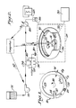
- FIG. 1 there may be seen an annular ringlike (even ribbonlike) channel 10 having a relatively small thickness (in the radial dimension) designated W.
- the channel has an inlet 12 in which the mobile phase or liquid is introduced together with, at some point in time, a small sample of a particulate to be fractionated, and an outlet 14.
- the annular channel is spun in either direction.
- the channel is illustrated as being rotated in a counterclockwise direction denoted by the arrow 16.
- these channels may be in the order to magnitude of 0.025 cm thick; actually, the smaller the channel thickness, the greater rate at which separations can be achieved and the greater the resolution of the separations.
- the flow of the liquid is laminar and it assumes a parabolic flow velocity profile across the channel thickness, as denoted by the reference numeral 18.
- the channel 10 is defined by an outer surface or wall 22 and an inner surface or wall 23. If now a radial centrifugal force field F, denoted by the arrow 20, is impressed transversely, that is at right angles to the channel, particulates are compressed into a dynamic cloud with an exponential concentration profile, whose average height or distance from the outer wall 22 is determined by the equilibrium between the average force exerted on each particulate by the field F and by the normal opposing diffusion forces due to Brownian motion.
- any given particulate can be found at any distance from the wall. Over a long period of time compared to the diffusion time, every particulate in the cloud will have been at every different height from the wall many times. However, the average height from the wall of all of the individual particulates of a given mass over that time period will be the same. Thus, the average height of the particulates from the wall will depend on the mass of the particulates, larger particulates having an average height 1A (Fig. 1) and that is less than that of smaller particulates 1 E3 (Fig. 1).
- a cluster of relatively small particulates 1 is ahead of the elutes first from the channel, whereas a cluster of larger, heavier particulates 1A is noticed to be distributed more closely to the outer wall 22 and obviously being subjected to the slower moving components of the fluid flow will elute at a later point in time.
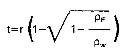
- the inner wall 23 of the flow channel 10 to have a thickness t that is related to the density of the fluid flowing through the channel, the radius of the channel, and the density of the material used to form the inner wall 23 of the channel. This relationship is more easily understood with reference to Fig. 6.
- centrifugal force acts in the direction of the arrow 100 tending to produce a counter pressure to that of the channel fluid.
- the wall force F w acting on the wall elemental area dA can be express as wall mass times angular acceleration giving: where Pw in the wall material density, w is the rotational speed, and the term is the radius of the center of gravity of the wall element of thickness t and area dA.
- the opposing fluid pressure force Fp is equal to the fluid pressure P acting over the same elemental area dA resulting in: where p ⁇ is the fluid density, r is again the wall radius which is the radius of the fluid which is continuous from the centerline of rotation, and w is the angular speed.
- a split ring channel as shown in Fig. 3 having an extremely small, constant thickness dimension W may be used to maintain resolution even in the presence of relatively large centrifugal force fields.
- the apparatus illustrated in Fig. 2 is particularly useful with this invention.
- the channel 10 may be disposed in a bowl-like or ring-like rotor 26 for support.
- the rotor 26 may be part of a conventional centrifuge, denoted by the dashed block 29, which includes a suitable centrifuge drive 30 of a known type operating through a suitable linkage 32, also a known type, which may be direct belt or gear drive.
- a bowl-like rotor is illustrated, it is to be understood that the assembly of channel 10 and rotor 26 may be supported for rotation about its own cylinder axis by any suitable means such as a spider (not shown), simple bowl, or disk, etc.
- the channel has a liquid or fluid inlet 12 and an outlet 14 which are coupled through a rotating seal 28, of conventional design, to the stationary apparatus which comprise the rest of the system.
- the inlet fluid (or liquid) or mobile phase of the system is derived from suitable solvent reservoirs 31 which are coupled through a conventional pump 32 thence through a two-way, 6-port sampling valve 34 of conventional design through a rotating seal 28, also of the conventional design, to the inlet 12.
- Samples whose particulates are to be separated are introduced into the flowing fluid stream by this conventional sampling valve 34 in which a sample loop 36 has either end connected to opposite ports of the valve 34 with a syringe 38 being coupled to an adjoining port.
- An exhaust or waste receptacle 40 is coupled to the final port.
- sample fluid may be introduced into the sample loop 36 with sample flowing through the sample loop to the exhaust receptacle 40. Fluid from the solvent reservoirs 31 in the meantime flows directly through the sample valve 34.
- the sample valve 34 is changed to a second position, depicted by the dashed lines 42, the ports move one position such that the fluid stream from the reservoir 31 now flows through the sample loop 36 before flowing . to the rotating seal 28.
- the syringe 38 is coupled directly to the exhaust reservoir 40.
- the sample is carried by the fluid stream to the rotating seal 28.
- the outlet line 14 from the channel 10 is coupled through the rotating seal 28 to a.conventional detector 44 and thence to an exhaust or collector receptacle 46.
- the detector may be any of the conventional types, such as an ultraviolet absorption or a light scattering detector.
- the analog electrical output of this detector may be connected as desired to a suitable recorder 48 of known type and in addition may be connected as denoted by the dashed line 50 to a suitable computer for analyzing this data.
- this system may be automated, if desired, by allowing the computer to control the operation of the pump 33 and also the operation of the centrifuge 29. Such control is depicted by the dashed lines 52 and 54, respectively.
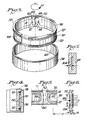
- the channel 10 of the apparatus has a configuration as is particularly depicted in Figs. 3, 4 and 5. It is annular in configuration such that fluid flows circumferentially through the channel.
- the channel is comprised particularly of an outer ring 56, which is in the form of a band having a constant radius, and functions to provide strength to support an inner ring.
- the outer ring may be supported by a spider, bowl or disc which is driven directly by the centrifuge drive 32 (Fig. 2).
- the outer ring may be eliminated and the bowl rotor substituted.
- the bowl rotor has a flattened inner surface formed thereon to provide the outer channel wall.
- the outer ring need not be separately mounted inside a support structure (26 of Fig. 2).
- the inner ring 58 is split, i.e., its longitudinal circumference is divided or separated to have a gap 60 with the longitudinal ends 62 of the inner ring 58 slightly tapered so as to facilitate the use of wedges 69.
- Wedges 69 retain the inner ring sufficiently expanded so as to maintain contact with the outer ring 56 at all times even when stopped.
- the thickness of the inner ring (Fig. 6) is selected in accordance with the above-noted relationship, i.e., it is directly proportional to the inside wall radius times the quantity
- An entire range of inner rings 58 may be constructed for use with a single outer ring 56 (or rotor if the outer ring is the rotor), a different thickness being used in the manufacture of each inner ring to accommodate different solvents that may be used in the flow channel.
- a single inner ring may be constructed whose thickness t represents a compromise thickness lying in the middle of the range of solvents to be used.
- the radially outer wall 66 of the inner ring 58 and the radially inner wall 68 of the outer ring 56 are formed to have a microfinish. This may be accomplished by polishing, for example, or by coating the surfaces with a suitable material either directly or by use of an insert. This smooth finish tends to reduce the possibility that particles will stick to the walls or become entrapped in small crevices or depressions of a depth equal to average concentration depth 1 of the particle cloud and also insures that the expected sample retention takes place.
- a groove 70 may be formed in the outer wall 66 of the inner ring 58 so as to form the flow channel itself or the conduit itself through which the fluid may flow.
- subsidiary grooves 72 may be formed to accommodate a resilient seal 74 such as an 0-ring which completely surrounds the tracks along the entire edges of the channel, including the end sections as may be seen most clearly in Fig. 5.
- the groove is generally curved as at 73.
- the upper edge of the inner ring is formed with a radial outwardly extending flange 76, as is seen most clearly in Fig. 4, such that the inner ring may rest upon and be supported by the outer ring against axially downward displacement.
- This then permits the formation of the narrow flow passage or channel itself which may be designated by the reference numeral 80 as is seen most clearly in Fig. 4.
- the thickness W of this channel 80 is relatively small, typically being in the order of 0.1 cm or less.
- either end of the channel 80 is provided with an inlet orifice 12 in the form of a bore through the inner ring and an outlet orifice 14, also in the form of a bore through the inner ring 58.
- spanner holes 82 may be formed in the inner ring to facilitate disassembly of the channel.
- the flow channel 10 may be constructed as depicted in Fig. 7 of a unitary channel, i.e., the inner and outer walls may be welded or joined together by other suitable means.
- the unitary channel depicted by the numeral 102 has an inner wall 104 whose thickness t is selected in accordance with the above relationships.
- this channel 102 is split such that it may, as depicted in Fig. 2, fit within a bowl type rotor or on a spider as previously described with the inlet and outlet lines 12 and 14 connected to either end.
Landscapes
- Centrifugal Separators (AREA)
Claims (3)
Applications Claiming Priority (2)
| Application Number | Priority Date | Filing Date | Title |
|---|---|---|---|
| US06/125,850 US4284497A (en) | 1980-02-29 | 1980-02-29 | Rotor for sedimentation field flow fractionation |
| US125850 | 1999-03-24 |
Publications (3)
| Publication Number | Publication Date |
|---|---|
| EP0035397A2 EP0035397A2 (fr) | 1981-09-09 |
| EP0035397A3 EP0035397A3 (en) | 1983-03-16 |
| EP0035397B1 true EP0035397B1 (fr) | 1986-07-23 |
Family
ID=22421716
Family Applications (1)
| Application Number | Title | Priority Date | Filing Date |
|---|---|---|---|
| EP81300842A Expired EP0035397B1 (fr) | 1980-02-29 | 1981-02-27 | Rotor pour la séparation de particules dans un fluide en écoulement avec application d'un champ de forces de sédimentation |
Country Status (5)
| Country | Link |
|---|---|
| US (1) | US4284497A (fr) |
| EP (1) | EP0035397B1 (fr) |
| JP (1) | JPS56139150A (fr) |
| CA (1) | CA1148912A (fr) |
| DE (1) | DE3174958D1 (fr) |
Families Citing this family (6)
| Publication number | Priority date | Publication date | Assignee | Title |
|---|---|---|---|---|
| US4353795A (en) * | 1981-04-01 | 1982-10-12 | E. I. Du Pont De Nemours And Company | Field flow fractionation channel |
| DE3278129D1 (en) * | 1981-12-08 | 1988-03-31 | Ici Plc | Sedimentation field flow fractionation |
| DK146284A (da) * | 1983-03-11 | 1984-09-12 | Du Pont | Partikeltaellingssystem til en fraktioneringsanordning |
| GB2205257B (en) * | 1986-06-17 | 1991-05-01 | Jeol Ltd | A column for continuous particle fractionation in a centrifugal force field |
| EP2524734B1 (fr) * | 2011-05-20 | 2015-01-14 | Postnova Analytics GmbH | Dispositif pour la mise en oeuvre d'un fractionnement par effet centrifuge dans un fluide en écoulement comprenant un joint pour réduire les fuites et procédé pour la mise en oeuvre d'un tel fractionnement |
| US11433404B2 (en) | 2016-12-22 | 2022-09-06 | Shimadzu Corporation | Centrifugal field-flow fractionation device having a restricting member to prevent deformation of an intermediate layer |
Family Cites Families (3)
| Publication number | Priority date | Publication date | Assignee | Title |
|---|---|---|---|---|
| DE2104372A1 (de) * | 1970-02-02 | 1971-08-19 | Kerby C | Zentrifuge |
| CA1041445A (fr) * | 1973-04-09 | 1978-10-31 | Sam Rose | Methode et appareil pour la culture continue in vitro de suspensions de cellules |
| US4430072A (en) * | 1977-06-03 | 1984-02-07 | International Business Machines Corporation | Centrifuge assembly |
-
1980
- 1980-02-29 US US06/125,850 patent/US4284497A/en not_active Expired - Lifetime
-
1981
- 1981-02-26 CA CA000371821A patent/CA1148912A/fr not_active Expired
- 1981-02-27 DE DE8181300842T patent/DE3174958D1/de not_active Expired
- 1981-02-27 EP EP81300842A patent/EP0035397B1/fr not_active Expired
- 1981-02-28 JP JP2768981A patent/JPS56139150A/ja active Pending
Also Published As
| Publication number | Publication date |
|---|---|
| EP0035397A2 (fr) | 1981-09-09 |
| EP0035397A3 (en) | 1983-03-16 |
| US4284497A (en) | 1981-08-18 |
| DE3174958D1 (en) | 1986-08-28 |
| CA1148912A (fr) | 1983-06-28 |
| JPS56139150A (en) | 1981-10-30 |
Similar Documents
| Publication | Publication Date | Title |
|---|---|---|
| EP0035398B1 (fr) | Rotor pour la séparation de particules dans un fluide en écoulement avec application d'un champ de forces de sédimentation | |
| EP0035396B1 (fr) | Procédé et dispositif pour la séparation de particules dans un fluide en écoulement avec application d'un champ de forces | |
| US3825175A (en) | Centrifugal particle elutriator and method of use | |
| US4214981A (en) | Steric field-flow fractionation | |
| US4353795A (en) | Field flow fractionation channel | |
| US4357235A (en) | Drive for rotating seal | |
| Mannweiler et al. | The scale-down of an industrial disc stack centrifuge | |
| US4448679A (en) | Apparatus and method for sedimentation field flow fractionation | |
| Fuh et al. | Analytical SPLITT fractionation: rapid particle size analysis and measurement of oversized particles | |
| Giddings | Field-flow fractionation | |
| US4446015A (en) | Field flow fractionation channel | |
| EP0035397B1 (fr) | Rotor pour la séparation de particules dans un fluide en écoulement avec application d'un champ de forces de sédimentation | |
| EP0035394B1 (fr) | Dispositif pour la séparation de particules dans un fluide en écoulement avec application d'un champ de forces | |
| Kirkland et al. | Sedimentation field flow fractionation: applications | |
| US4743227A (en) | Column for continuous particle fractionation apparatus utilizing centrifugal field | |
| US4446014A (en) | Sedimentation field flow fractionation channel and method | |
| US4900435A (en) | Centrifugal fast chromatograph | |
| US4414106A (en) | Method and apparatus for improving sedimentation field flow fractionation channels | |
| EP0035395B1 (fr) | Conduit pour la séparation de particules dans un fluide en écoulement avec application d'un champ de forces de sédimentation | |
| Li et al. | Particle characterization in centrifugal fields: comparison between ultracentrifugation and sedimentation field-flow fractionation | |
| US4356083A (en) | Unbalanced rotor for field flow fractionation channel | |
| Giddings | Two-dimensional field-flow fractionation | |
| Jones et al. | Colloid characterization by sedimentation field-flow fractionation: V. Split outlet system for complex colloids of mixed density | |
| JPS5935266B2 (ja) | 場流れ分画方法および装置 | |
| Koliadima et al. | Sedimentation field-flow fractionation: A new methodology for the concentration and particle size analysis of dilute polydisperse colloidal samples |
Legal Events
| Date | Code | Title | Description |
|---|---|---|---|
| PUAI | Public reference made under article 153(3) epc to a published international application that has entered the european phase |
Free format text: ORIGINAL CODE: 0009012 |
|
| AK | Designated contracting states |
Designated state(s): BE CH DE FR GB IT LI NL |
|
| 17P | Request for examination filed |
Effective date: 19811215 |
|
| PUAL | Search report despatched |
Free format text: ORIGINAL CODE: 0009013 |
|
| AK | Designated contracting states |
Designated state(s): BE CH DE FR GB IT LI NL |
|
| GRAA | (expected) grant |
Free format text: ORIGINAL CODE: 0009210 |
|
| AK | Designated contracting states |
Kind code of ref document: B1 Designated state(s): BE CH DE FR GB IT LI NL |
|
| ITF | It: translation for a ep patent filed | ||
| REF | Corresponds to: |
Ref document number: 3174958 Country of ref document: DE Date of ref document: 19860828 |
|
| ET | Fr: translation filed | ||
| PGFP | Annual fee paid to national office [announced via postgrant information from national office to epo] |
Ref country code: NL Payment date: 19870228 Year of fee payment: 7 |
|
| PLBE | No opposition filed within time limit |
Free format text: ORIGINAL CODE: 0009261 |
|
| STAA | Information on the status of an ep patent application or granted ep patent |
Free format text: STATUS: NO OPPOSITION FILED WITHIN TIME LIMIT |
|
| 26N | No opposition filed | ||
| PG25 | Lapsed in a contracting state [announced via postgrant information from national office to epo] |
Ref country code: LI Effective date: 19880229 Ref country code: CH Effective date: 19880229 |
|
| BERE | Be: lapsed |
Owner name: E.I. DU PONT DE NEMOURS AND CY Effective date: 19880228 |
|
| PG25 | Lapsed in a contracting state [announced via postgrant information from national office to epo] |
Ref country code: NL Effective date: 19880901 |
|
| NLV4 | Nl: lapsed or anulled due to non-payment of the annual fee | ||
| PG25 | Lapsed in a contracting state [announced via postgrant information from national office to epo] |
Ref country code: FR Free format text: LAPSE BECAUSE OF NON-PAYMENT OF DUE FEES Effective date: 19881028 |
|
| REG | Reference to a national code |
Ref country code: CH Ref legal event code: PL |
|
| PG25 | Lapsed in a contracting state [announced via postgrant information from national office to epo] |
Ref country code: DE Effective date: 19881101 |
|
| GBPC | Gb: european patent ceased through non-payment of renewal fee | ||
| PG25 | Lapsed in a contracting state [announced via postgrant information from national office to epo] |
Ref country code: GB Free format text: LAPSE BECAUSE OF NON-PAYMENT OF DUE FEES Effective date: 19881118 |
|
| REG | Reference to a national code |
Ref country code: FR Ref legal event code: ST |
|
| PG25 | Lapsed in a contracting state [announced via postgrant information from national office to epo] |
Ref country code: BE Effective date: 19890228 |