EP0034509B1 - Dispositif de commande hydraulique perfectionné - Google Patents
Dispositif de commande hydraulique perfectionné Download PDFInfo
- Publication number
- EP0034509B1 EP0034509B1 EP81400025A EP81400025A EP0034509B1 EP 0034509 B1 EP0034509 B1 EP 0034509B1 EP 81400025 A EP81400025 A EP 81400025A EP 81400025 A EP81400025 A EP 81400025A EP 0034509 B1 EP0034509 B1 EP 0034509B1
- Authority
- EP
- European Patent Office
- Prior art keywords
- case
- cylinder
- tubular sleeve
- piston
- cavity
- Prior art date
- Legal status (The legal status is an assumption and is not a legal conclusion. Google has not performed a legal analysis and makes no representation as to the accuracy of the status listed.)
- Expired
Links
Images
Classifications
-
- F—MECHANICAL ENGINEERING; LIGHTING; HEATING; WEAPONS; BLASTING
- F15—FLUID-PRESSURE ACTUATORS; HYDRAULICS OR PNEUMATICS IN GENERAL
- F15B—SYSTEMS ACTING BY MEANS OF FLUIDS IN GENERAL; FLUID-PRESSURE ACTUATORS, e.g. SERVOMOTORS; DETAILS OF FLUID-PRESSURE SYSTEMS, NOT OTHERWISE PROVIDED FOR
- F15B15/00—Fluid-actuated devices for displacing a member from one position to another; Gearing associated therewith
- F15B15/08—Characterised by the construction of the motor unit
- F15B15/14—Characterised by the construction of the motor unit of the straight-cylinder type
- F15B15/1423—Component parts; Constructional details
- F15B15/1438—Cylinder to end cap assemblies
Definitions
- the present invention relates to hydraulic control devices as used, in particular although not exclusively, in a helicopter mast rotor, to ensure the control of the general or collective pitch, of the cyclic pitch, and / or of the lateral pitch or warping of the blades.
- Such a device comprises, in a known construction, a cylinder formed by a cylinder body made of treated light alloy and which is machined so as to delimit a cylindrical chamber with which a piston cooperates, as well as various conduits and passages forming part of the hydraulic circuit.
- a cylinder body made of treated light alloy and which is machined so as to delimit a cylindrical chamber with which a piston cooperates, as well as various conduits and passages forming part of the hydraulic circuit.
- this cylinder body are conventionally fixed bearings and end caps or covers, as well as a hydraulic control unit which is arranged so as to provide a servo-control of the movable element of the device, which in the particular application envisaged above is constituted by the cylinder body itself, the piston plate being kept fixed.
- Document FR-A-1 472 230 discloses an arrangement of this type in which, moreover, the jack comprises a casing in which is housed a jacket delimiting with the casing an annular chamber serving as a supply pipe for the caster .
- the object of this invention is mainly to provide a hydraulic control device which, while fulfilling the same functions, ie of a cost price significantly lower in manufacturing as in maintenance, and also offers a reduced weight.
- the envelope can be produced in such a way that it simultaneously constitutes the actuating member connected to the swash plate forming part of the mechanism for varying the pitch of the blades.
- a hydraulic control device which can for example be used to vary the pitch of the blades of a helicopter or else to control a light airplane control surface.
- this device is connected upstream by a linkage to a control member. actuated by the pilot and downstream it is connected to the actual pitch variation mechanism, in this case to the lower element of the swashplate (also not shown). It is understood, however, that such a device can have many other different applications while offering the same advantages.
- the input member is therefore here constituted by a lever L and its output member by a "trumpet" T ".
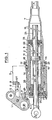
- the device mainly comprises a cylinder 1 of axis XX with hydraulic control, and a servo-control block 2 whose functions will be explained with reference to FIG: 3.
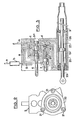
- the lever L is articulated at 3 on a support 4 linked to the block 2. It is connected by a link 5 to a sliding drawer 6 and can be blocked relative to block 2 by a lock 7.
- the hydraulic servo-control unit 2 comprises a body 8 pierced right through with three lights 8 ", 8 1 , gc of parallel axes in which the cylinder 1, the latch 7 and the drawer 6 and its sleeve are received respectively
- This block 2 also comprises two end faces perpendicular to the axis XX, and is preferably produced by spinning a light alloy, the profile obtained then being cut to length and machined.
- the jack 1 comprises two main parts: an envelope 9 and a jacket 10.
- the envelope 9 comprises a roughly cylindrical part 11 extended by a part 12 of progressively decreasing section which constitutes the "trumpet" T.
- This envelope 9 also includes a recessed end skirt 13 with a seal in a portion 14 of larger diameter of the housing 5 °, and an outer flange 15 delimiting an approximately radial face 16 bearing on the adjacent face 17 of the block 2, and a frustoconical bearing 18 on which engages a bearing of complementary shape 19 with a flange 20 for fixing to the block.
- the type of fixing used is shown in Fig.
- the casing 9 also comprises a cylindrical internal surface 22 and an internal radial shoulder 23 allowing the positioning and the abutment of a first end element or bottom 24 which constitutes on the one hand, a support member for the jacket 10, and secondly, a bearing for the piston rod 25.
- the jacket 10 has an outer diameter slightly less than that of the bore 22 of the envelope and also slightly less than the diameter of the housing 8 1 defined in the control unit 2. It thus defines with these two parts an annular chamber 26 which , in the example chosen, is constantly in communication with the chamber 27 of the cylinder delimited between this jacket 10, the piston 25a, the piston rod-25 and the bottom 24.
- the device is completed by considering the left part of FIG. 1 by a second end element 28 mounted with a seal in the housing 8a of the control unit 2 and which serves, on the one hand, as an axial and radial support for the jacket 10 and, on the other hand as a bearing for the rod 25, thus playing a role similar to that fulfilled by element 24.
- An end cover here constituted by support 4 is fixed on the control unit 2 and completes the assembly while ensuring the blocking of element 28
- the second chamber of the jack is designated by the reference 29.
- the piston rod 25 extends in the example chosen on either side of the piston itself 25a with which it is made integral by any suitable means and this rod can be constituted by a hollow tube.
- a distributor c is supplied with a filter b, with the interposition of a filter b (eg distributor 4/3, which makes it possible to selectively supply two conduits d , e connected respectively to the chambers 27 and 29 of the jack.
- the conduit d in fact opens into the annular chamber 26 connected to the chamber 27.
- the conduit e passes through the rear part of the bore 8b of the lock 7, the internal end acts on a valve f which can open or close the communication between the two conduits d and e.
- a conduit g brings the pressurized fluid into the front part of the bore 8 b and a path h is also provided back to the tarp, from the dispenser.
- this jacket 10 in association with the fact that this jacket 10 is subjected to an axial force of prestress in compression, that it can have a relatively small thickness.
- This jacket does not in fact intervene for the transmission of forces which is carried out in normal operation by means of the casing and the hydraulic fluid.
- the latch 7 blocks the lever L relative to the block 2 and the conduits d and e are put in communication. The mobile assembly is then moved at the same time as the lever L and the force is transmitted directly by the block 2 and the casing 9.
- the casing 9 can be obtained by hammering or stamping-spinning if it is made of light alloy, or even by molding and / or winding if it is made of high-strength plastic resin.
- the liner 10 also made of light alloy, it is simply constituted by a calibrated, sectioned and treated tube.
- the control unit 2 can be manufactured by spinning an aluminum alloy or molding a high-strength plastic resin, the additional machining operations being much less numerous. This device can thus have a significantly reduced weight compared to that of a device manufactured by traditional methods.
Landscapes
- Engineering & Computer Science (AREA)
- Physics & Mathematics (AREA)
- Fluid Mechanics (AREA)
- Mechanical Engineering (AREA)
- General Engineering & Computer Science (AREA)
- Actuator (AREA)
Applications Claiming Priority (2)
| Application Number | Priority Date | Filing Date | Title |
|---|---|---|---|
| FR8001592A FR2474613A1 (fr) | 1980-01-25 | 1980-01-25 | Dispositif de commande hydraulique perfectionne |
| FR8001592 | 1980-01-25 |
Publications (2)
| Publication Number | Publication Date |
|---|---|
| EP0034509A1 EP0034509A1 (fr) | 1981-08-26 |
| EP0034509B1 true EP0034509B1 (fr) | 1985-05-02 |
Family
ID=9237861
Family Applications (1)
| Application Number | Title | Priority Date | Filing Date |
|---|---|---|---|
| EP81400025A Expired EP0034509B1 (fr) | 1980-01-25 | 1981-01-09 | Dispositif de commande hydraulique perfectionné |
Country Status (4)
| Country | Link |
|---|---|
| US (1) | US4414881A (enExample) |
| EP (1) | EP0034509B1 (enExample) |
| DE (1) | DE3170219D1 (enExample) |
| FR (1) | FR2474613A1 (enExample) |
Families Citing this family (8)
| Publication number | Priority date | Publication date | Assignee | Title |
|---|---|---|---|---|
| GB2127340B (en) * | 1982-09-03 | 1986-02-26 | Macdonald & Company John | Apparatus for scabbling concrete |
| DE3535006A1 (de) * | 1984-10-03 | 1986-04-17 | Zahnradfabrik Friedrichshafen Ag, 7990 Friedrichshafen | Servolenkmotor |
| US4785721A (en) * | 1986-07-15 | 1988-11-22 | Leigh Monstevens Keith V | Hydraulic cylinder annular insert for retainer member |
| JPS6315306U (enExample) * | 1986-07-16 | 1988-02-01 | ||
| US5117741A (en) * | 1990-01-16 | 1992-06-02 | Sta-Rite Industries, Inc. | Double wall hydraulic cylinder |
| DE4128959A1 (de) * | 1991-08-30 | 1993-03-04 | Schaeff Karl Gmbh & Co | Schaufellader-kippzylinder |
| FR2684953B1 (fr) * | 1991-12-11 | 1994-04-01 | Aerospatiale Ste Nationale Indle | Dispositif a vulnerabilite reduite pour la commande d'un rotor d'helicoptere par plateaux cycliques. |
| AT409788B (de) | 2000-07-26 | 2002-11-25 | Hoerbiger Micro Fluid Gmbh | Druckmittelzylinder |
Citations (2)
| Publication number | Priority date | Publication date | Assignee | Title |
|---|---|---|---|---|
| FR1280935A (fr) * | 1961-01-31 | 1962-01-08 | Armstrong Patents Co Ltd | Perfectionnements aux servo-mécanismes hydrauliques |
| FR1472230A (fr) * | 1966-01-27 | 1967-03-10 | Citroen Sa Andre | Dispositif de commande assistée de boîte de vitesses |
Family Cites Families (5)
| Publication number | Priority date | Publication date | Assignee | Title |
|---|---|---|---|---|
| US3158068A (en) * | 1961-12-28 | 1964-11-24 | Conair | Hydraulic actuator and control unit |
| US3176721A (en) * | 1963-10-04 | 1965-04-06 | Clark Equipment Co | Hydraulic valve |
| FR2094275A5 (enExample) * | 1970-06-16 | 1972-02-04 | Hm Hobson Limited | |
| US4207807A (en) * | 1975-09-04 | 1980-06-17 | Oiles Industry Co., Ltd. | Plastic air cylinder assembly |
| US4050359A (en) * | 1975-09-04 | 1977-09-27 | Brunswick Corporation | Hydraulic power trim and power tilt system supply |
-
1980
- 1980-01-25 FR FR8001592A patent/FR2474613A1/fr active Granted
-
1981
- 1981-01-09 DE DE8181400025T patent/DE3170219D1/de not_active Expired
- 1981-01-09 EP EP81400025A patent/EP0034509B1/fr not_active Expired
- 1981-01-21 US US06/227,111 patent/US4414881A/en not_active Expired - Lifetime
Patent Citations (2)
| Publication number | Priority date | Publication date | Assignee | Title |
|---|---|---|---|---|
| FR1280935A (fr) * | 1961-01-31 | 1962-01-08 | Armstrong Patents Co Ltd | Perfectionnements aux servo-mécanismes hydrauliques |
| FR1472230A (fr) * | 1966-01-27 | 1967-03-10 | Citroen Sa Andre | Dispositif de commande assistée de boîte de vitesses |
Also Published As
| Publication number | Publication date |
|---|---|
| FR2474613A1 (fr) | 1981-07-31 |
| EP0034509A1 (fr) | 1981-08-26 |
| DE3170219D1 (en) | 1985-06-05 |
| FR2474613B1 (enExample) | 1983-11-18 |
| US4414881A (en) | 1983-11-15 |
Similar Documents
| Publication | Publication Date | Title |
|---|---|---|
| EP0006045B1 (fr) | Dispositif de commande pour circuit de fluide et vérin autonome dans lequel est intégré un tel circuit | |
| EP0034509B1 (fr) | Dispositif de commande hydraulique perfectionné | |
| FR2644765A2 (fr) | Frein electromagnetique a machoires de serrage | |
| FR2493452A1 (fr) | Mecanisme de transmission a poulies coniques et a reglage continu | |
| EP0072311B1 (fr) | Distributeur hydraulique pour moteur d'assistance à rappel vers la position de repos | |
| EP0805278B1 (fr) | Dispositif de vérin pneumatique | |
| FR2704463A1 (fr) | Procédé et dispositif destinés à réaliser une denture profilée sur un arbre. | |
| EP0012043B1 (fr) | Dispositif de direction assistée hydraulique pour véhicule automobile | |
| EP0302786A1 (fr) | Machine rotative à pistons et à barillet avec rotule de centrage fixe | |
| FR2474427A1 (fr) | Dispositif de direction du type a cremaillere et a pignon pour vehicules, comportant des moyens d'evacuation de l'air et des bulles contenus dans le cylindre-moteur | |
| FR2468775A1 (fr) | Distributeur hydraulique | |
| EP0176381B1 (fr) | Distributeur hydraulique haute pression, à générateur de pression de pilotage | |
| FR2695183A1 (fr) | Soupape pilote, destinée notamment à être utilisée dans un système hydraulique d'exploitation minière. | |
| FR2722844A1 (fr) | Servomoteur hydraulique | |
| EP0473739B1 (fr) | Dispositif de dressage d'un fil metallique | |
| EP0192547A1 (fr) | Dispositif de commande pour maître cylindre double | |
| EP0800026A1 (fr) | Actionneur électrohydraulique pour la commande d'une boite de vitesses de véhicule du type à barillet d'entrée | |
| EP0033669B1 (fr) | Dispositif de servo-commande et son application aux appareils de commande de vol des aéronefs | |
| EP1252703A1 (fr) | Arbre d'induit de moteur electrique comportant un pignon de sortie, et son application dans un demarreur de vehicule | |
| EP1103878A1 (fr) | Robinet détendeur | |
| BE1011007A3 (fr) | Vanne en ligne autoverrouillable. | |
| CH249913A (fr) | Mandrin pour broche de tour automatique. | |
| EP3087288B1 (fr) | Frein à disque à commande hydraulique comportant un frein de stationnement à actionnement hydraulique | |
| FR2509381A1 (fr) | Pompe a injection de carburant | |
| EP1069397B1 (fr) | Capteur de déplacement pour verins de servo-commande |
Legal Events
| Date | Code | Title | Description |
|---|---|---|---|
| PUAI | Public reference made under article 153(3) epc to a published international application that has entered the european phase |
Free format text: ORIGINAL CODE: 0009012 |
|
| AK | Designated contracting states |
Designated state(s): DE GB IT |
|
| 17P | Request for examination filed |
Effective date: 19810915 |
|
| ITF | It: translation for a ep patent filed | ||
| GRAA | (expected) grant |
Free format text: ORIGINAL CODE: 0009210 |
|
| AK | Designated contracting states |
Designated state(s): DE GB IT |
|
| REF | Corresponds to: |
Ref document number: 3170219 Country of ref document: DE Date of ref document: 19850605 |
|
| PLBE | No opposition filed within time limit |
Free format text: ORIGINAL CODE: 0009261 |
|
| STAA | Information on the status of an ep patent application or granted ep patent |
Free format text: STATUS: NO OPPOSITION FILED WITHIN TIME LIMIT |
|
| 26N | No opposition filed | ||
| ITTA | It: last paid annual fee | ||
| PGFP | Annual fee paid to national office [announced via postgrant information from national office to epo] |
Ref country code: GB Payment date: 20000118 Year of fee payment: 20 |
|
| PGFP | Annual fee paid to national office [announced via postgrant information from national office to epo] |
Ref country code: DE Payment date: 20000201 Year of fee payment: 20 |
|
| PG25 | Lapsed in a contracting state [announced via postgrant information from national office to epo] |
Ref country code: GB Free format text: LAPSE BECAUSE OF EXPIRATION OF PROTECTION Effective date: 20010108 |
|
| REG | Reference to a national code |
Ref country code: GB Ref legal event code: PE20 Effective date: 20010108 |