EP0034134A1 - Rock bolting apparatus - Google Patents
Rock bolting apparatus Download PDFInfo
- Publication number
- EP0034134A1 EP0034134A1 EP81850017A EP81850017A EP0034134A1 EP 0034134 A1 EP0034134 A1 EP 0034134A1 EP 81850017 A EP81850017 A EP 81850017A EP 81850017 A EP81850017 A EP 81850017A EP 0034134 A1 EP0034134 A1 EP 0034134A1
- Authority
- EP
- European Patent Office
- Prior art keywords
- rock
- swingable
- bolting apparatus
- unit
- feed
- Prior art date
- Legal status (The legal status is an assumption and is not a legal conclusion. Google has not performed a legal analysis and makes no representation as to the accuracy of the status listed.)
- Granted
Links
Images


Classifications
-
- E—FIXED CONSTRUCTIONS
- E21—EARTH DRILLING; MINING
- E21D—SHAFTS; TUNNELS; GALLERIES; LARGE UNDERGROUND CHAMBERS
- E21D20/00—Setting anchoring-bolts
- E21D20/003—Machines for drilling anchor holes and setting anchor bolts
Definitions
- This invention relates to a rock bolting apparatus including a rock drill and a bolt setting machine, and more particularly to an apparatus wherein drilling, bolting and, if desired, resin insertion, can be accurately and quickly carried out in succession.
- Such a rock bolting apparatus is previously known from German Patent Specification No 22 22 646.
- This known apparatus has a feed bar which is common to the rock drill and the bolt setting machine, the rock drill and the bolt setting machine being situated on two opposite sides of the common feed bar.
- the drill rod and the rock bolt are guided by respective supports located at the end of the feed bar which is directed towards the rock surface.
- at least the drill rod support should abut against the rock surface.
- rock bolting often takes place in tunnels with a rough surface or else the bolting could be needed obliquely to the surface.
- the bolt support will often hit projecting rock parts before the drill support has gotten sufficient abutment against the rock surface.
- the drill support often hits projecting or other rock parts when the swingable unit is turned to the position for inserting resin cartridges or bolts.
- the drill hole will not always be as required because of adjoining rock irregularities or because the bolt will not be inserted sufficiently deep in the drill hole.
- a rock bolting apparatus includes at least a rock drill and a bolt setting machine both of which are carried by a swingable unit connected to a boom, the swingable unit being swingable relative to the boom about an axis; power means for power displacing the rock drill and the bolt setting machine laterally into and out of a working position by means of controlled swinging of the swingable unit about said axis; and clamping means for clamping the swingable unit between a rock surface and the boom, the clamping means including a jack arranged on the swingable unit and being extensible in alignment with said axis.
- the swingable unit comprises a first feed bar movably mounted thereon and carrying the rock drill for feeding and guiding the rock drill; a second feed bar (27) movably mounted thereon and carrying the bolt setting machine; and power displacing means coupled to the feed bars for power displacing the two feed bars independently of each other relative to the swingable unit in the longitudinal direction of the feed bars.
- first and second feed bars are mounted relative to said axis such that on swinging movement of the swingable unit about said axis, both said rock drill and said bolt setting machine are in alignment with the hole being drilled.
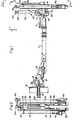
- a boom 11 mounted to a suitable transportable chassis 12 by a universal joint 13.
- the boom 11 is laterally swingable by means of a hydraulic cylinder 14 arranged between the chassis 12 and the joint 13 while vertical movement of the boom 11 is achieved by a pair of cylinders 15 arranged between the joint 13 and the arm 11.
- a vertically swingable supporting means 16 is attached to the free end of the boom 11.
- The-swinging motion of supporting means 16 is achieved by a hydraulic cylinder 17 arranged between the boom 11 and the supporting means 16.
- a swingable unit 18 is in turn attached to the supporting means 16 by two bearings 19 and 20 and is laterally swingable relative to the arm 11 about an axis 21 by means of a pair of cylinders 22 arranged between the supporting means 16 and the swingable unit 18.
- the two cylinders 22 are arranged in some suitable way in order to give their piston rods 23 three distinct mechanical stop positions whereby the swingable unit 18 is given three defined working positions.
- the unit 18 is shown in its second working position in which the piston rods 23 are projected to half their length against a middle stop position.
- the swingable unit 18 has a central box-shaped supporting frame 24 with brackets 25 arranged thereon, the brackets 25 holding a first 26 and a second 27 feed bar on two opposite sides of the frame 24.
- the feed bars 26 and 27 are displaceable relative to the frame 24 by the operation of hydraulic cylinders 28 and 29 (Figs 4), each of which is connected to a respective feed bar 26 and 27.
- the cylinders 28 and 29 are arranged side by side in a plane through the axis 21 as seen in Fig 3. In Fig 4 the cylinders are, for clarity, shown side by side in a plane perpendicular to said first plane. They may take other positions.
- the cylinders 28 and 29 are located in the frame 24 having their piston rods 30 and 31 protruding from the upper part of said frame 24 and being attached to respective brackets 32 and 33 on the respective feed bar 26, 27.
- the feed bars 26 and 27 are displaceable by means of cylinders 28 and 29 in a direction parallel to the axis 21. During such motion the feed bars 26, 27 are guided by tracks 34 mounted on two opposite sides of the feed bars and being adapted to run in corresponding notches in the brackets 25.
- the feed bars 26 and 27 may each be constructed as the feed bar disclosed in German Patent Specification No 28 20 325, but also other feed bars can be suitable.
- an impact rock drill 40 is arranged on a cradle which is feedable in a conventional way along the first bar 26.
- a drill rod 42 connected to the rock drill 40 goes through a hole in a drill support 43 arranged at the upper end of the feed bar 26.
- the support 43 includes a cushion 44 of an elastic material which is adapted to abut against the rock. surface 45 and having a hole 46 therein whose diameter is adapted to the drill bit to enable the drill bit to be at least partly drawn into the cusion 44 and to be guided by the same when collaring a hew hole.
- the support 43 includes further an elastic sleeve 47 whose hole is equal to the diameter of the drill rod 42 and is dapted for guiding said drill rod 42.
- a bowl- shaped part 48 is located between the cusion 44 and the sleeve 47 and is arranged for collecting the flushing water mixed with cuttings flowing out of the drill hole 49.
- a machine 50 for setting bolts 51 is arranged on the second feed bar 27.
- the machine 50 comprises a nut running tool with fluid-pressure drive mounted on a cradle 52 movable along the feed bar 27.
- the head of the bolt 51 is receivable in a rotatable socket 53 also carrying a washer 54 threaded on the bolt 51.
- a support 55 for the bolt 51 is arranged at the upper part of the feed bar 27 and includes an arm 56 which is turnable aside.
- the arm 56 has a gripping means 57 adapted for gripping and guiding the bolt 51.
- a charging tube 58 for resin cartridges is carried by the supporting frame 24 and is axially displaceable by an hydraulic motor 59.
- the lower end 60 of the tube 58 is connectable to a hose (not shown) in which the resin cartridges are inserted and pneumatically transported to the drill hole 49.
- the unit 18 further includes an upwardly protruding frame part 62 having an hydraulic jack 63 disposed therein.
- Jack 63 whose upper part is shown in Fig 5 comprises an hydraulic cylinder 64 mounted to the upper end surface of the frame part 62.
- a piston rod 65 is extensible from the cylinder 64,said rod 65 having a bearing sleeve 66 screwed on the free end thereof.
- the bearing sleeve 66 carries a clamping head 67 journalled on the sleeve by a radial bearing race 68 and an axial bearing race 69. As a result of the bearing shape, rotation of the clamping head 67 is allowed without any declination in relation to the piston rod.
- the clamping head 67 is adapted to abut against the rock surface when the apparatus is used and has therefore a cushion 70 of elastic material for providing a favorable grip against the rock.
- the rotation axis of the clamping head 67 is arranged to coincide with the longitudinal axis 71 of the hydraulic cylinder 64, said axis 71 in turn coinciding with the axis 2L
- the drill rod 42, the charging tube 58 and the bolts 51 are so disposed that they are in parallel to the axis 21 and are located the same distance from axis 21. At the swinging movement of the swingable unit 18, these devices 42, 58, 51 will therefore describe a motion along one and the same arc 72 as indicated by the chain- dotted line in Fig 3.
- the apparatus is set in the drilling position by displacing the piston rods 23, Fig 3, to their full length so they will reach their external stop position.
- the unit 18. is thus turned 45° to the first working position in which the drill rod 42 will coincide with the charging tube 58 position shown in Fig 3.
- the first feed bar 26 is positioned so that the drill rod 42 will point at the desired drilling position for the bolt.
- the bar 26 is displaced towards the rock surface 45, causing the drill support 43 to abut thereagainst as seen in Fig 4.
- the hydraulic cylinder 64, Fig 5 is activated to press the clamping head 67 towards the rock to thus clamp the unit 18 between the rock and the arm or boom 11.
- the feed bar 26 is further pressed against the rock by the hydraulic cylinder 28, Fig 4, enabling the clamping head 67 to be fed in succession thereto and to thereby protrude still another bit to increase the clamping effect. Thereafter the feed bar 26 is somewhat withdrawn while the hydraulic cylinder 64 is kept in its extended position by means of a suitable hydraulic lock (not shown).
- a suitable hydraulic lock (not shown).
- the charging tube 58 is fed up into the hole by the hydraulic motor 59 and resin cartridges are inserted in a suitable way.
- the charging tube 58 is drawn back from the hole and the unit 18 is turned another 45° to the third working position in which the bolt 51 will be aligned with the drill hole 49.
- the third position will be defined by drawing back the piston rods 23 into cylinders 22 to their inner stop position.
- the feed bar 27 for the bolt setting machine 50 is now positioned a suitable distance from the rock surface so the bolt 51 can be inserted to a sufficient depth by means of the-bolt setting machine 50.
- the bolt 51 is guided by the gripping means 57 until the bolt has gone so far into the hole as the washer 54 must pass the arm 56.
- the gripping means 57 will at that time release the guiding grip about the bolt and is folded upwards, thus enabling the washer 54 and the.machine 50 to be brought to abutment against the rock surface.
- the bolt 51 is then in a known way fixed to the rock by harde- ening of the resin and tightening of the bolt.
- the bolting operation is now completed and the clamping head 67 is drawn back so that the unit 18 is set free and is able to be.positioned for another bolting operation.
- the apparatus can be positioned so that the one feed bar which is brought to a working position will be situated sufficiently close to the rock surface to enable satisfactory guidance and feed length to the drill rod and bolts without being hindered by the other feed bar hitting irregularities in the rock.
Abstract
Description
- This invention relates to a rock bolting apparatus including a rock drill and a bolt setting machine, and more particularly to an apparatus wherein drilling, bolting and, if desired, resin insertion, can be accurately and quickly carried out in succession.
- Such a rock bolting apparatus is previously known from German Patent Specification
No 22 22 646. This known apparatus has a feed bar which is common to the rock drill and the bolt setting machine, the rock drill and the bolt setting machine being situated on two opposite sides of the common feed bar. The drill rod and the rock bolt are guided by respective supports located at the end of the feed bar which is directed towards the rock surface. To achieve an effective guidance, at least the drill rod support should abut against the rock surface. However, rock bolting often takes place in tunnels with a rough surface or else the bolting could be needed obliquely to the surface. When using this prior art apparatus under such circumstances, the bolt support will often hit projecting rock parts before the drill support has gotten sufficient abutment against the rock surface. Correspondingly, the drill support often hits projecting or other rock parts when the swingable unit is turned to the position for inserting resin cartridges or bolts. As a result of these disadvantages, the drill hole will not always be as required because of adjoining rock irregularities or because the bolt will not be inserted sufficiently deep in the drill hole. - It is an object of this invention to provide a rock bolting apparatus avoiding the disadvantages of the kind mentioned above and which apparatus will make it possible to insert rock bolts by machine power even if the rock surface is uneven or inclined.
- In accordance with the invention, a rock bolting apparatus includes at least a rock drill and a bolt setting machine both of which are carried by a swingable unit connected to a boom, the swingable unit being swingable relative to the boom about an axis; power means for power displacing the rock drill and the bolt setting machine laterally into and out of a working position by means of controlled swinging of the swingable unit about said axis; and clamping means for clamping the swingable unit between a rock surface and the boom, the clamping means including a jack arranged on the swingable unit and being extensible in alignment with said axis. The improvement of the invention resides in that the swingable unit comprises a first feed bar movably mounted thereon and carrying the rock drill for feeding and guiding the rock drill; a second feed bar (27) movably mounted thereon and carrying the bolt setting machine; and power displacing means coupled to the feed bars for power displacing the two feed bars independently of each other relative to the swingable unit in the longitudinal direction of the feed bars.
- In a preferred arrangement, the first and second feed bars are mounted relative to said axis such that on swinging movement of the swingable unit about said axis, both said rock drill and said bolt setting machine are in alignment with the hole being drilled.
- In the drawings:
- Fig 1 is a side view of a rock bolting apparatus according to the invention;
- Fig 2 is a view seen as indicated by the arrows 2-2 in Fig 1;
- Fig 3'is a view seen from above as indicated by the arrows 3-3 in Fig 1 but on an enlarged scale; .
- Fig 4 is a cross-section along the line 4-4 in Fig 3 but on a somewhat reduced scale; and
- Fig 5 is a fragmentary cross-section along the line 5-5 in Fig 3 but on an enlarged scale.
- In Fig 1 there is shown a boom 11 mounted to a suitable
transportable chassis 12 by auniversal joint 13. The boom 11 is laterally swingable by means of ahydraulic cylinder 14 arranged between thechassis 12 and thejoint 13 while vertical movement of the boom 11 is achieved by a pair ofcylinders 15 arranged between thejoint 13 and the arm 11. A verticallyswingable supporting means 16 is attached to the free end of the boom 11. The-swinging motion of supportingmeans 16 is achieved by ahydraulic cylinder 17 arranged between the boom 11 and the supportingmeans 16. Aswingable unit 18 is in turn attached to the supportingmeans 16 by twobearings axis 21 by means of a pair ofcylinders 22 arranged between the supportingmeans 16 and theswingable unit 18. - The two
cylinders 22 are arranged in some suitable way in order to give theirpiston rods 23 three distinct mechanical stop positions whereby theswingable unit 18 is given three defined working positions. In Figs 1-3 theunit 18 is shown in its second working position in which thepiston rods 23 are projected to half their length against a middle stop position. - As seen in Figs 2 and 4, the
swingable unit 18 has a central box-shaped supportingframe 24 withbrackets 25 arranged thereon, thebrackets 25 holding a first 26 and a second 27 feed bar on two opposite sides of theframe 24. Thefeed bars frame 24 by the operation ofhydraulic cylinders 28 and 29 (Figs 4), each of which is connected to arespective feed bar cylinders axis 21 as seen in Fig 3. In Fig 4 the cylinders are, for clarity, shown side by side in a plane perpendicular to said first plane. They may take other positions. Thecylinders frame 24 having theirpiston rods frame 24 and being attached torespective brackets respective feed bar feed bars cylinders axis 21. During such motion thefeed bars tracks 34 mounted on two opposite sides of the feed bars and being adapted to run in corresponding notches in thebrackets 25. - The
feed bars Patent Specification No 28 20 325, but also other feed bars can be suitable. - As seen in Figs 1-4, an
impact rock drill 40 is arranged on a cradle which is feedable in a conventional way along thefirst bar 26. Adrill rod 42 connected to therock drill 40 goes through a hole in adrill support 43 arranged at the upper end of thefeed bar 26. Thesupport 43 includes acushion 44 of an elastic material which is adapted to abut against the rock.surface 45 and having ahole 46 therein whose diameter is adapted to the drill bit to enable the drill bit to be at least partly drawn into thecusion 44 and to be guided by the same when collaring a hew hole. Thesupport 43 includes further anelastic sleeve 47 whose hole is equal to the diameter of thedrill rod 42 and is dapted for guiding saiddrill rod 42. A bowl-shaped part 48 is located between thecusion 44 and thesleeve 47 and is arranged for collecting the flushing water mixed with cuttings flowing out of thedrill hole 49. - A
machine 50 for settingbolts 51 is arranged on thesecond feed bar 27. Themachine 50 comprises a nut running tool with fluid-pressure drive mounted on acradle 52 movable along thefeed bar 27. The head of thebolt 51 is receivable in arotatable socket 53 also carrying awasher 54 threaded on thebolt 51. Asupport 55 for thebolt 51 is arranged at the upper part of thefeed bar 27 and includes anarm 56 which is turnable aside. Thearm 56 has a gripping means 57 adapted for gripping and guiding thebolt 51. When.the washer abuts thearm 56, thearm 56 and gripping means 57 are swung upwardly about pivot 61 (Fig 3) so that the gripping of thebolt 51 is released and the washer may pass upwardly past thearm 56 and gripping means 57. - A
charging tube 58 for resin cartridges is carried by the supportingframe 24 and is axially displaceable by anhydraulic motor 59. Thelower end 60 of thetube 58 is connectable to a hose (not shown) in which the resin cartridges are inserted and pneumatically transported to thedrill hole 49. - The
unit 18 further includes an upwardly protrudingframe part 62 having anhydraulic jack 63 disposed therein.Jack 63 whose upper part is shown in Fig 5 comprises anhydraulic cylinder 64 mounted to the upper end surface of theframe part 62. Apiston rod 65 is extensible from thecylinder 64,saidrod 65 having abearing sleeve 66 screwed on the free end thereof. Thebearing sleeve 66 carries a clampinghead 67 journalled on the sleeve by a radial bearingrace 68 and an axial bearingrace 69. As a result of the bearing shape, rotation of the clampinghead 67 is allowed without any declination in relation to the piston rod. Theclamping head 67 is adapted to abut against the rock surface when the apparatus is used and has therefore acushion 70 of elastic material for providing a favorable grip against the rock. The rotation axis of theclamping head 67 is arranged to coincide with thelongitudinal axis 71 of thehydraulic cylinder 64, saidaxis 71 in turn coinciding with the axis 2L Thedrill rod 42, thecharging tube 58 and thebolts 51 are so disposed that they are in parallel to theaxis 21 and are located the same distance fromaxis 21. At the swinging movement of theswingable unit 18, thesedevices same arc 72 as indicated by the chain- dotted line in Fig 3. - The operation of the rock bolting apparatus will now be further described. First the apparatus is set in the drilling position by displacing the
piston rods 23, Fig 3, to their full length so they will reach their external stop position. The unit 18.is thus turned 45° to the first working position in which thedrill rod 42 will coincide with thecharging tube 58 position shown in Fig 3. Then thefirst feed bar 26 is positioned so that thedrill rod 42 will point at the desired drilling position for the bolt. Then, thebar 26 is displaced towards therock surface 45, causing thedrill support 43 to abut thereagainst as seen in Fig 4. Then thehydraulic cylinder 64, Fig 5, is activated to press theclamping head 67 towards the rock to thus clamp theunit 18 between the rock and the arm or boom 11. To increase the clamping force, thefeed bar 26 is further pressed against the rock by thehydraulic cylinder 28, Fig 4, enabling the clampinghead 67 to be fed in succession thereto and to thereby protrude still another bit to increase the clamping effect. Thereafter thefeed bar 26 is somewhat withdrawn while thehydraulic cylinder 64 is kept in its extended position by means of a suitable hydraulic lock (not shown). By the described cooperation between thehydraulic cylinders hydraulic cylinder 64 of the clampinghead 67 should have been used, thus enabling the indexing to be accurately done about one carefully fixedaxis 21. During the setting of theunit 18 against the rock, both thefeed bar 27 for thebolts 51 and the chargingtube 58 are displaced backwards so that they will not knock against irregularities in the rock surface. - When the unit is satisfactorily clamped against the rock the drilling is started. During the collaring the drill bit is guided by the
hole 46 in thecushion 44 while the drill rod throughout the complete drilling operation is guided by thesleeve 47. When the required hole depth has been reached thedrilling machine 40 with thedrill rod 42 is fed backwards and thefeed bar 26 is displaced from the rock by thehydraulic cylinder 28. Then thepiston rods 23 are drawn back intocylinders 22 to their middle stop position making theunit 18turn 450 about theaxis 21 while the clampinghead 67 is maintained in immovable abutment against the rock. Theunit 18 will now be in the second working position which is that position shown in Fig 3 with the chargingtube 58 located in alignment with thedrill hole 49. The chargingtube 58 is fed up into the hole by thehydraulic motor 59 and resin cartridges are inserted in a suitable way. When the charging operation has been completed the chargingtube 58 is drawn back from the hole and theunit 18 is turned another 45° to the third working position in which thebolt 51 will be aligned with thedrill hole 49. The third position will be defined by drawing back thepiston rods 23 intocylinders 22 to their inner stop position. Thefeed bar 27 for thebolt setting machine 50 is now positioned a suitable distance from the rock surface so thebolt 51 can be inserted to a sufficient depth by means of the-bolt setting machine 50. During insertion, thebolt 51 is guided by the grippingmeans 57 until the bolt has gone so far into the hole as thewasher 54 must pass thearm 56. The gripping means 57 will at that time release the guiding grip about the bolt and is folded upwards, thus enabling thewasher 54 andthe.machine 50 to be brought to abutment against the rock surface. Thebolt 51 is then in a known way fixed to the rock by harde- ening of the resin and tightening of the bolt. The bolting operation is now completed and the clampinghead 67 is drawn back so that theunit 18 is set free and is able to be.positioned for another bolting operation. - By virtue of the fact that the bolting apparatus comprising two
feed bars
Claims (10)
Priority Applications (1)
| Application Number | Priority Date | Filing Date | Title |
|---|---|---|---|
| AT81850017T ATE7728T1 (en) | 1980-02-08 | 1981-02-03 | MACHINE FOR SETTING MOUNTAIN ANCHORS. |
Applications Claiming Priority (2)
| Application Number | Priority Date | Filing Date | Title |
|---|---|---|---|
| SE8001018A SE420856C (en) | 1980-02-08 | 1980-02-08 | MOUNTAIN BOLTING UNIT INCLUDING A DRILLING MACHINE AND A MACHINE FOR INSTALLATION OF BULTS |
| SE8001018 | 1980-02-08 |
Publications (2)
| Publication Number | Publication Date |
|---|---|
| EP0034134A1 true EP0034134A1 (en) | 1981-08-19 |
| EP0034134B1 EP0034134B1 (en) | 1984-05-30 |
Family
ID=20340210
Family Applications (1)
| Application Number | Title | Priority Date | Filing Date |
|---|---|---|---|
| EP81850017A Expired EP0034134B1 (en) | 1980-02-08 | 1981-02-03 | Rock bolting apparatus |
Country Status (9)
| Country | Link |
|---|---|
| EP (1) | EP0034134B1 (en) |
| JP (1) | JPS56139396A (en) |
| AT (1) | ATE7728T1 (en) |
| AU (1) | AU6697481A (en) |
| DE (1) | DE3163791D1 (en) |
| FI (1) | FI810312L (en) |
| NO (1) | NO810356L (en) |
| SE (1) | SE420856C (en) |
| ZA (1) | ZA8127B (en) |
Cited By (9)
| Publication number | Priority date | Publication date | Assignee | Title |
|---|---|---|---|---|
| FR2520800A1 (en) * | 1982-02-02 | 1983-08-05 | Eimco Secoma | DRILLING AND BOLTING TURRET |
| FR2526479A1 (en) * | 1982-05-06 | 1983-11-10 | Eimco Secoma | DEVICE FOR RECEIVING BOLTS AND MAINTAINING THEM DURING LAYING ON A BORING AND BOLTING TURRET |
| EP0130969A2 (en) * | 1983-06-30 | 1985-01-09 | BÖHLER PNEUMATIK INTERNATIONAL GESELLSCHAFT m.b.H. | Drilling and bolting apparatus |
| EP0146009A1 (en) * | 1983-11-28 | 1985-06-26 | Mario Lolli | Device for driving ground anchors for anchoring fluid conveying pipelines to the ground |
| DE3416144A1 (en) * | 1984-05-02 | 1985-11-07 | Franz Schell GmbH Hydraulik- und Maschinenbau, 6969 Höpfingen | Device for anchoring the roof and wall of low and narrow mine galleries |
| US6698529B2 (en) * | 2001-04-20 | 2004-03-02 | Oldenburg Cannon, Inc. | Translating turret rock bolter |
| FR2862337A1 (en) * | 2003-11-18 | 2005-05-20 | Sandvik Tamrock Secoma Sas | DRILLING AND BOLTING HEAD FOR BOLTING MACHINE |
| WO2013127407A1 (en) * | 2012-03-02 | 2013-09-06 | Dh Mining System Gmbh | System for drilling holes and for placing rock bolts |
| US9856733B2 (en) | 2012-07-09 | 2018-01-02 | Atlas Copco Rock Drills Ab | Method and rock bolting rig for installation of a rock bolt |
Families Citing this family (5)
| Publication number | Priority date | Publication date | Assignee | Title |
|---|---|---|---|---|
| US4398850A (en) * | 1981-02-09 | 1983-08-16 | Copper Range Company | Roof bolter and process |
| SE8303851L (en) * | 1983-07-06 | 1985-01-07 | Johnson Construction Co Ab | SET AND EQUIPMENT FOR DRILLING IN MOUNTAINS WITH LOW PALL HEIGHT |
| CH668453A5 (en) * | 1985-10-24 | 1988-12-30 | Sig Schweiz Industrieges | Ankerbohrvorrichtung. |
| SE531009C2 (en) * | 2005-05-03 | 2008-11-18 | Atlas Copco Rock Drills Ab | Device and method for installing a rock bolt and a rock bolt installation rig |
| JP7252850B2 (en) * | 2019-07-16 | 2023-04-05 | 鹿島建設株式会社 | Rock bolt construction device and rock bolt construction method |
Citations (1)
| Publication number | Priority date | Publication date | Assignee | Title |
|---|---|---|---|---|
| FR2417628A1 (en) * | 1978-02-21 | 1979-09-14 | Lorraine Houilleres | EXTENSIBLE SLIDE SUPPORT |
-
1980
- 1980-02-08 SE SE8001018A patent/SE420856C/en unknown
-
1981
- 1981-01-02 ZA ZA00810027A patent/ZA8127B/en unknown
- 1981-01-09 JP JP131381A patent/JPS56139396A/en active Pending
- 1981-02-03 AT AT81850017T patent/ATE7728T1/en not_active IP Right Cessation
- 1981-02-03 EP EP81850017A patent/EP0034134B1/en not_active Expired
- 1981-02-03 DE DE8181850017T patent/DE3163791D1/en not_active Expired
- 1981-02-03 NO NO810356A patent/NO810356L/en unknown
- 1981-02-04 FI FI810312A patent/FI810312L/en not_active Application Discontinuation
- 1981-02-06 AU AU66974/81A patent/AU6697481A/en not_active Abandoned
Patent Citations (1)
| Publication number | Priority date | Publication date | Assignee | Title |
|---|---|---|---|---|
| FR2417628A1 (en) * | 1978-02-21 | 1979-09-14 | Lorraine Houilleres | EXTENSIBLE SLIDE SUPPORT |
Cited By (12)
| Publication number | Priority date | Publication date | Assignee | Title |
|---|---|---|---|---|
| FR2520800A1 (en) * | 1982-02-02 | 1983-08-05 | Eimco Secoma | DRILLING AND BOLTING TURRET |
| FR2526479A1 (en) * | 1982-05-06 | 1983-11-10 | Eimco Secoma | DEVICE FOR RECEIVING BOLTS AND MAINTAINING THEM DURING LAYING ON A BORING AND BOLTING TURRET |
| EP0130969A2 (en) * | 1983-06-30 | 1985-01-09 | BÖHLER PNEUMATIK INTERNATIONAL GESELLSCHAFT m.b.H. | Drilling and bolting apparatus |
| EP0130969A3 (en) * | 1983-06-30 | 1986-11-05 | Vereinigte Edelstahlwerke Aktiengesellschaft (Vew) | Drilling and bolting apparatus |
| AT384860B (en) * | 1983-06-30 | 1988-01-25 | Ver Edelstahlwerke Ag | ANCHOR DRILLING AND SETTING DEVICE |
| EP0146009A1 (en) * | 1983-11-28 | 1985-06-26 | Mario Lolli | Device for driving ground anchors for anchoring fluid conveying pipelines to the ground |
| DE3416144A1 (en) * | 1984-05-02 | 1985-11-07 | Franz Schell GmbH Hydraulik- und Maschinenbau, 6969 Höpfingen | Device for anchoring the roof and wall of low and narrow mine galleries |
| US6698529B2 (en) * | 2001-04-20 | 2004-03-02 | Oldenburg Cannon, Inc. | Translating turret rock bolter |
| FR2862337A1 (en) * | 2003-11-18 | 2005-05-20 | Sandvik Tamrock Secoma Sas | DRILLING AND BOLTING HEAD FOR BOLTING MACHINE |
| EP1533470A1 (en) * | 2003-11-18 | 2005-05-25 | Sandvik Tamrock Secoma S.A.S. | Drilling and bolting head for a bolting machine |
| WO2013127407A1 (en) * | 2012-03-02 | 2013-09-06 | Dh Mining System Gmbh | System for drilling holes and for placing rock bolts |
| US9856733B2 (en) | 2012-07-09 | 2018-01-02 | Atlas Copco Rock Drills Ab | Method and rock bolting rig for installation of a rock bolt |
Also Published As
| Publication number | Publication date |
|---|---|
| SE420856C (en) | 1985-03-24 |
| NO810356L (en) | 1981-08-10 |
| SE8001018L (en) | 1981-08-09 |
| AU6697481A (en) | 1981-08-13 |
| FI810312L (en) | 1981-08-09 |
| SE420856B (en) | 1981-11-02 |
| EP0034134B1 (en) | 1984-05-30 |
| DE3163791D1 (en) | 1984-07-05 |
| ATE7728T1 (en) | 1984-06-15 |
| JPS56139396A (en) | 1981-10-30 |
| ZA8127B (en) | 1982-02-24 |
Similar Documents
| Publication | Publication Date | Title |
|---|---|---|
| EP0034134B1 (en) | Rock bolting apparatus | |
| AU638142B2 (en) | Device for setting a rock bolt | |
| US3977480A (en) | Arrangement for exchanging drill bits | |
| US3741322A (en) | Drilling rig with drill rod magazine | |
| CN210359963U (en) | Automatic welding machine with multiple welding guns at tail part of hollow grouting anchor cable | |
| AU599167B2 (en) | Method and device for driving a tunnel | |
| US2340572A (en) | Clamp and supporting bar for drills | |
| US5050283A (en) | Arrangement for handling drill rods in a rock drilling unit or the like | |
| US3965997A (en) | Method and apparatus for guiding and sealing a drill string | |
| US3333488A (en) | Annular drilling machine | |
| US2261017A (en) | Combined mine drill and breaker | |
| US3489040A (en) | Method of deep bore drilling | |
| US4307593A (en) | Apparatus for forming collars around openings in tubes or plates | |
| CN212535666U (en) | Angle-adjustable leading small catheter guiding device | |
| CN210360302U (en) | Follow-on five metals drilling equipment | |
| JPH086547B2 (en) | Rod changer | |
| CN210068020U (en) | Drilling machine with drill rod centralizing function | |
| JP2835551B2 (en) | Double tube rod handling device | |
| EP1948901A1 (en) | Method and device at rock drilling | |
| CN217950279U (en) | Blasting drilling positioner | |
| CN217667551U (en) | Simple welding tool for diamond drill bit | |
| CN208374269U (en) | It is a kind of for processing the drilling equipment of mine drill | |
| CN220409223U (en) | High-precision drilling device | |
| CN217710717U (en) | Supporting device for tubular pile installation and positioning | |
| CN217570978U (en) | Auxiliary positioning device for machining automobile chassis accessories |
Legal Events
| Date | Code | Title | Description |
|---|---|---|---|
| PUAI | Public reference made under article 153(3) epc to a published international application that has entered the european phase |
Free format text: ORIGINAL CODE: 0009012 |
|
| AK | Designated contracting states |
Designated state(s): AT CH DE FR GB IT |
|
| 17P | Request for examination filed |
Effective date: 19820211 |
|
| ITF | It: translation for a ep patent filed |
Owner name: BARZANO' E ZANARDO ROMA S.P.A. |
|
| GRAA | (expected) grant |
Free format text: ORIGINAL CODE: 0009210 |
|
| AK | Designated contracting states |
Designated state(s): AT CH DE FR GB IT LI |
|
| PG25 | Lapsed in a contracting state [announced via postgrant information from national office to epo] |
Ref country code: FR Free format text: THE PATENT HAS BEEN ANNULLED BY A DECISION OF A NATIONAL AUTHORITY Effective date: 19840530 |
|
| REF | Corresponds to: |
Ref document number: 7728 Country of ref document: AT Date of ref document: 19840615 Kind code of ref document: T |
|
| PG25 | Lapsed in a contracting state [announced via postgrant information from national office to epo] |
Ref country code: LI Effective date: 19840604 Ref country code: CH Effective date: 19840604 |
|
| REF | Corresponds to: |
Ref document number: 3163791 Country of ref document: DE Date of ref document: 19840705 |
|
| REG | Reference to a national code |
Ref country code: CH Ref legal event code: PL |
|
| PG25 | Lapsed in a contracting state [announced via postgrant information from national office to epo] |
Ref country code: AT Effective date: 19850203 |
|
| PLBE | No opposition filed within time limit |
Free format text: ORIGINAL CODE: 0009261 |
|
| STAA | Information on the status of an ep patent application or granted ep patent |
Free format text: STATUS: NO OPPOSITION FILED WITHIN TIME LIMIT |
|
| 26N | No opposition filed | ||
| RAP2 | Party data changed (patent owner data changed or rights of a patent transferred) |
Owner name: ATLAS COPCO AKTIEBOLAG |
|
| GBPC | Gb: european patent ceased through non-payment of renewal fee | ||
| PG25 | Lapsed in a contracting state [announced via postgrant information from national office to epo] |
Ref country code: DE Effective date: 19851101 |
|
| PG25 | Lapsed in a contracting state [announced via postgrant information from national office to epo] |
Ref country code: GB Effective date: 19881118 |
|
| PG25 | Lapsed in a contracting state [announced via postgrant information from national office to epo] |
Ref country code: LI Free format text: LAPSE BECAUSE OF NON-PAYMENT OF DUE FEES Effective date: 19840604 |