EP0034033A1 - Regelung eines elektrischen Motorantriebssystems - Google Patents
Regelung eines elektrischen Motorantriebssystems Download PDFInfo
- Publication number
- EP0034033A1 EP0034033A1 EP81300432A EP81300432A EP0034033A1 EP 0034033 A1 EP0034033 A1 EP 0034033A1 EP 81300432 A EP81300432 A EP 81300432A EP 81300432 A EP81300432 A EP 81300432A EP 0034033 A1 EP0034033 A1 EP 0034033A1
- Authority
- EP
- European Patent Office
- Prior art keywords
- signal
- motor
- pulses
- command signal
- drive
- Prior art date
- Legal status (The legal status is an assumption and is not a legal conclusion. Google has not performed a legal analysis and makes no representation as to the accuracy of the status listed.)
- Granted
Links
- 238000006073 displacement reaction Methods 0.000 claims abstract description 28
- 238000012545 processing Methods 0.000 claims abstract description 22
- 230000004048 modification Effects 0.000 claims abstract description 10
- 238000012986 modification Methods 0.000 claims abstract description 10
- 238000000034 method Methods 0.000 claims description 5
- 230000001419 dependent effect Effects 0.000 claims 2
- 230000004044 response Effects 0.000 description 7
- 230000008859 change Effects 0.000 description 4
- 238000003754 machining Methods 0.000 description 4
- 238000013459 approach Methods 0.000 description 3
- 238000009760 electrical discharge machining Methods 0.000 description 3
- 230000008569 process Effects 0.000 description 3
- 230000008878 coupling Effects 0.000 description 2
- 238000010168 coupling process Methods 0.000 description 2
- 238000005859 coupling reaction Methods 0.000 description 2
- 238000012937 correction Methods 0.000 description 1
- 238000001514 detection method Methods 0.000 description 1
- 238000010586 diagram Methods 0.000 description 1
- 239000013536 elastomeric material Substances 0.000 description 1
- 230000006698 induction Effects 0.000 description 1
- 230000000977 initiatory effect Effects 0.000 description 1
- 230000005291 magnetic effect Effects 0.000 description 1
- 239000000463 material Substances 0.000 description 1
- 230000003287 optical effect Effects 0.000 description 1
Images
Classifications
-
- H—ELECTRICITY
- H02—GENERATION; CONVERSION OR DISTRIBUTION OF ELECTRIC POWER
- H02P—CONTROL OR REGULATION OF ELECTRIC MOTORS, ELECTRIC GENERATORS OR DYNAMO-ELECTRIC CONVERTERS; CONTROLLING TRANSFORMERS, REACTORS OR CHOKE COILS
- H02P5/00—Arrangements specially adapted for regulating or controlling the speed or torque of two or more electric motors
-
- G—PHYSICS
- G05—CONTROLLING; REGULATING
- G05B—CONTROL OR REGULATING SYSTEMS IN GENERAL; FUNCTIONAL ELEMENTS OF SUCH SYSTEMS; MONITORING OR TESTING ARRANGEMENTS FOR SUCH SYSTEMS OR ELEMENTS
- G05B19/00—Programme-control systems
- G05B19/02—Programme-control systems electric
- G05B19/18—Numerical control [NC], i.e. automatically operating machines, in particular machine tools, e.g. in a manufacturing environment, so as to execute positioning, movement or co-ordinated operations by means of programme data in numerical form
- G05B19/19—Numerical control [NC], i.e. automatically operating machines, in particular machine tools, e.g. in a manufacturing environment, so as to execute positioning, movement or co-ordinated operations by means of programme data in numerical form characterised by positioning or contouring control systems, e.g. to control position from one programmed point to another or to control movement along a programmed continuous path
- G05B19/21—Numerical control [NC], i.e. automatically operating machines, in particular machine tools, e.g. in a manufacturing environment, so as to execute positioning, movement or co-ordinated operations by means of programme data in numerical form characterised by positioning or contouring control systems, e.g. to control position from one programmed point to another or to control movement along a programmed continuous path using an incremental digital measuring device
- G05B19/23—Numerical control [NC], i.e. automatically operating machines, in particular machine tools, e.g. in a manufacturing environment, so as to execute positioning, movement or co-ordinated operations by means of programme data in numerical form characterised by positioning or contouring control systems, e.g. to control position from one programmed point to another or to control movement along a programmed continuous path using an incremental digital measuring device for point-to-point control
- G05B19/231—Numerical control [NC], i.e. automatically operating machines, in particular machine tools, e.g. in a manufacturing environment, so as to execute positioning, movement or co-ordinated operations by means of programme data in numerical form characterised by positioning or contouring control systems, e.g. to control position from one programmed point to another or to control movement along a programmed continuous path using an incremental digital measuring device for point-to-point control the positional error is used to control continuously the servomotor according to its magnitude
- G05B19/232—Numerical control [NC], i.e. automatically operating machines, in particular machine tools, e.g. in a manufacturing environment, so as to execute positioning, movement or co-ordinated operations by means of programme data in numerical form characterised by positioning or contouring control systems, e.g. to control position from one programmed point to another or to control movement along a programmed continuous path using an incremental digital measuring device for point-to-point control the positional error is used to control continuously the servomotor according to its magnitude with speed feedback only
-
- G—PHYSICS
- G05—CONTROLLING; REGULATING
- G05B—CONTROL OR REGULATING SYSTEMS IN GENERAL; FUNCTIONAL ELEMENTS OF SUCH SYSTEMS; MONITORING OR TESTING ARRANGEMENTS FOR SUCH SYSTEMS OR ELEMENTS
- G05B2219/00—Program-control systems
- G05B2219/30—Nc systems
- G05B2219/34—Director, elements to supervisory
- G05B2219/34215—Microprocessor
-
- G—PHYSICS
- G05—CONTROLLING; REGULATING
- G05B—CONTROL OR REGULATING SYSTEMS IN GENERAL; FUNCTIONAL ELEMENTS OF SUCH SYSTEMS; MONITORING OR TESTING ARRANGEMENTS FOR SUCH SYSTEMS OR ELEMENTS
- G05B2219/00—Program-control systems
- G05B2219/30—Nc systems
- G05B2219/34—Director, elements to supervisory
- G05B2219/34367—Interrupts, different tasks foreground, midground, background
-
- G—PHYSICS
- G05—CONTROLLING; REGULATING
- G05B—CONTROL OR REGULATING SYSTEMS IN GENERAL; FUNCTIONAL ELEMENTS OF SUCH SYSTEMS; MONITORING OR TESTING ARRANGEMENTS FOR SUCH SYSTEMS OR ELEMENTS
- G05B2219/00—Program-control systems
- G05B2219/30—Nc systems
- G05B2219/37—Measurements
- G05B2219/37313—Derive speed from position
-
- G—PHYSICS
- G05—CONTROLLING; REGULATING
- G05B—CONTROL OR REGULATING SYSTEMS IN GENERAL; FUNCTIONAL ELEMENTS OF SUCH SYSTEMS; MONITORING OR TESTING ARRANGEMENTS FOR SUCH SYSTEMS OR ELEMENTS
- G05B2219/00—Program-control systems
- G05B2219/30—Nc systems
- G05B2219/42—Servomotor, servo controller kind till VSS
- G05B2219/42237—Pwm pulse width modulation, pulse to position modulation ppm
Definitions
- the present invention relates to a motor drive control system and, more particularly, an improved control system for driving a motor to perform a desired displacement with an increased degree of precision and operating stability.
- a conventional drive control system for a motor may be equipped with a tacho-generator connected to the motor shaft for providing an electric signal.
- This signal may be used as a feed-back signal and applied to a driver circuit for controlling the rate of rotation or angular velocity of the motor in an attempt to increase the operating stability and precision of the motor.
- the tacho-generator can, however, be a significant load for the motor system and may seriously cause a drop of response thereby to an input drive signal.
- a drive control system for a motor comprising: a driver circuit for the motor; a signal input unit for receiving an input command signal representing a desired extent of angular displacement of the motor; a microcomputer having an input/output interface connected between the signal input unit and the driver circuit and a central processing unit or microprocessor for producing a control command signal in accordance with the input command signal and applying the control command signal to the driver circuit, thereby providing from the latter a drive signal for the motor in accordance with the control command signal; an encoder for sensing an angular displacement of the motor being achieved by the drive signal and producing a succession of pulses representing the angular displacement being sensed; logic-circuit means connected between the encoder and the input/output interface for applying to the microprocessor a feed-back signal at least derived from the output pulses of the encoder to modify the control command signal and consequentially the drive signal; and an interrupt unit associated with the microcomputer for intermittently providing an interrupt signal to the central processing unit thereby permitting the
- the driver circuit is preferably adapted to provide, as the drive signal, a series of drive pulses having an on-time ⁇ on and off-time ⁇ off at least one of which is variable.
- the on-time ⁇ on and/or off-time ⁇ off may be varied controlledly I by the afore-mentioned modification of the control command signal in the microprocessor.
- the signal input unit is preferably adapted to issue a succession of input command pulses defining the input command signal.
- the logic-circuit means may include a differential counter responsive to the input command pulses and to the output pulses of the encoder for producing an output signal representing a difference therebetween and applying the output signal through the interface to the central processing unit to form the control command signal therein.
- the logic-circuit means may further include a second differential counter responsive to the output pulses of the encoder and to a reference signal in the form of a succession of reference pulses furnished from the central processing unit through the input/output interface for providing an output signal representing a difference between the encoder output pulses and the reference pulses, the output signal of the second differential counter being returned through the interface to the microprocessor to produce the afore-mentioned modification of the control command signal.
- a second differential counter responsive to the output pulses of the encoder and to a reference signal in the form of a succession of reference pulses furnished from the central processing unit through the input/output interface for providing an output signal representing a difference between the encoder output pulses and the reference pulses, the output signal of the second differential counter being returned through the interface to the microprocessor to produce the afore-mentioned modification of the control command signal.
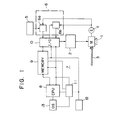
- a motor designated at 1 is rotated in response to a drive signal furnished by a driver circuit 2 which may be constituted as a power amplifier.
- a feed screw 3 is securely coupled to the rotary shaft of the motor 1 and used to carry a load not shown.
- the motor 3 is equipped with an encoder 4 for sensing the angle of rotation of the motor 1 shaft to provide an output signal in the form of digital pulses proportional in number to the instantaneous sensed angle of rotation.
- a displacement command signal (e.g. in the form a succession of pulses) to the system representing a desired extent of rotation is set at an input unit 5.
- a logic circuit unit 6 includes a first differential counter 6a which provides a difference between the input value of rotation at the input signal unit 5 and the sensed value of rotation being furnished by the encoder 4, and a second differential counter 6b which provides a difference between a reference value and the sensed value of rotation being furnished by the encoder 4.
- a microcomputer 7 is provided for computing from the input signal at the unit 5 an optimum velocity for the rotation of the motor 1 in accordance with the desired extent of rotation and includes a microprocessor or central processing unit (CPU) 8, a memory unit 9 and an input/output interface 10.
- a system controller 11 is provided for the central processing unit 8.
- An interrupt unit 12 is coupled to the controller 11 and the memory 9 to permit an interrupt to be accomplished at a preprogrammed time interval.
- a clock for the microcomputer 7 is shown at 13.
- a desired extent for the rotation of the motor 1 is set at the signal input unit 5.
- the set value in the form of a succession of pulses is transmitted via the first differential counter 6a to the microprocessor 7.
- the value is read by the central processing unit 8 successively in accordance with control signals furnished by the system controller 11 and is thereby processed to calculate an optimum velocity for the rotation or angular displacement of the motor 1.
- a signal in the form of pulses representing the optimum velocity is produced at the input/output interface 10 and applied via the amplifier/driver circuit 2 to the motor 1.
- the encoder 4 ro- tate s with the motor 1 shaft and provides a digital signal representing the driven rotation of the motor 1.
- the number of pulses furnished denotes the driven angular displacement of the motor 1.
- the number of pulses furnished per unit time denotes the angular velocity or the rate of driven rotation j of the motor 1.
- the difference between the input command and the encoder 4 output is provided by the differential counter 6a in the logic circuit 6 and applied to the microcomputer 7 through the interface 9.
- the central processing unit 8 in the microcomputer 7 processes the differential signal to furnish through the driver circuit 2 the drive signal for controlledly rotating the motor 1.
- the differential counter 6b in the logic circuit 6 is furnished with the reference value calculated by the central processing unit 8 and transmitted i through the interface 10 to the provide the difference between the reference value and the encoder 4 sensed output, the differential signal being then furnished through the interface 10.
- the central processing unit 8 responds to the differential signal to calculate a duty factor of drive pulses such as to make the difference nil or such that the sensed velocity approaches the optimum value established and to furnish the drive pulses with the calculated duty factor to the motor 1 through the driver circuit 2.
- the driver circuit 2 When an input command to this end is received at the input signal unit 5, the driver circuit 2 will operate to commence driving the motor 1 towards the end of achieving the commanded angular displacement. In the initial period of the rotation, the rate of rotation will be low and the velocity signal sensed by the encoder 4 will accordingly be a small value. As a result, the differential value which develops from the counter 6b will be large. Then the central processing circuit 8 each time an interrupt signal is incoming from the unit 12 will operate to determine a duty factor for the drive pulses such that the sensed velocity approaches the velocity range previously claculated and to command the drive circuit 2 that the drive pulses being applied to the motor 1 be modified to change the duty factor to the determined value.
- the drive pulses are controlled to increase the duty factor to increase the rate of rotation of the motor 1.
- a quick initiation of the rotation of the motor 1 is provided.
- an increase in the rate of rotation of the motor 1 causes the encoder 4 to proportionally develop an increased rate of sensing pulses which in turn reduces the differential signal provided by the differential counter 6b.
- the driver circuit 2 will be operated to produce the drive pulses of a reduced duty factor which are applied to the motor 1 to rotate it at a given angular velocity.
- the motor 1 will continue to rotate at the velocity which is held constant until it approaches the end of the commanded displacement.
- the differential signal from the counter 6a becomes smaller, causing the duty factor of the drive pulses to be modified to a lower value as a result of the computation at the CPU 8 and the consequential command to the drive circuit 2.
- the rate of rotation of the motor 1 is thus reduced.
- the reference value furnished to the differential counter 6b is controlled to be reduced to allow the motor 1 to continue to rotate as long as the differ ential output lies in a predetermined range.
- the central processing unit 8 will output a further duty-factor value for the drive pulses which is still lower to reduce the rate of rotation of the motor 1.
- the motor 1 is capable of being stopped extremely precisely at the very position commanded at the input signal unit 5, hiving achieved the angular displacement under microcomputer's directed velocity control in the process.
- the system initiates the control cycle.
- the differential counter 6a compares the command pulses of the input unit 5 and the sensing pulses of the encoder 4 and continues to issue a drive command to the motor 1 via the driver/amplifier circuit 2 until the sensing pulses in number reach the command pulses.
- the drive command is terminated to stop the motor 1.
- the C PU operates to control the drive signal issued from the driver/amplifier 2 to vary the rate of rotation of the motor 1 in an optimum mode in accordance with the extent of displacement given by the input command.
- the deviation of the velocity from a preselected range is ascertained from the sensing signal of the encoder 4,
- the duty factor of the drive pulses is altered by the processing operation of the CPU 8 in response to an interrupt signal from the unit 12 so as to return the velocity to the preselected range.
- the motor 1 commences rotating rapidly and with an accelerated rate of response to promptly reach a steady operation.
- the motor 1 is subject to a minimum of velocity change due to a variation in the load.
- the motor 1 stops rapidly and with an accelerated rate of response and without any over-travel. The result is an extremely high accuracy ; in stopping the motor 1 at the desired angular position.
- the signal input unit 5 may take any of various known forms. For example, data for a series of displacement commands may be memorized on a tape. A register may be used to memorize each unit of the data on the tape and to reproduce the same in the form of a succession of electrical pulses which are applied to the logic circuit 6. Alternatively, ROM and/or RAM may be used for the storage of the data which are reproduced by a selection circuit to provide a succession of electrical pulses to be applied to the logic circuit 6.
- a displacement command signal in the form of a succession of electrical pulses is produced in a servocontrol circuit connected to detect a parameter in the EDM gap formed between a tool electrode and a workpiece one of which is to be moved by the operation of the motor 1 to follow up the material removal process therein.
- the displacement command signal applied to the signal input unit may also be a time signal for determining the time in which the motor 1 is driven and thereby determining an extent of the rotation thereof.
- the rate of rotation or angular velocity is controlled in response to a change in the load in an optimum manner by applying the velocity detection signal of the encoder 4 to the CPU 8.
- the processing operation of the CPU 8 provides an in-process correction of the drive signal such that the motor 1 is rotated at a predetermined angular velocity in spite of a change in the load and hence with an increased stability of operation.
- the interrupt unit 12 as described previously provides an interrupt signal periodically or with predetermined time intervals.
- the time interval may optionally be taken and may be varied.
- a velocity signal derived from the encoder 4 is applied to the output from the interface 10 to the driver circuit 2.
- the CPU 8 performs the computation of an error from the desired displacement command and, when the result is found to be in the predetermined range, stops the operation without altering the duty factor of the control output. If the result is found to be outside the range, the CPU 8 proceeds to alter the duty factor, thereby modifying the angular velocity of the motor 1.
- This checking and modification operation is performed at predetermined or varying time intervals so that the rate of rotation is automatically held to be optimum with respect to the desired extent of angular displacement.
- the system controller 11 may be arranged to allow the interrupt signal from the unit 12 to be passed to the CPU 8 to permit the modification of the drive signal when the feed- back signal from the logic circuit 6 exceeds a predetermined value.
- the velocity modification with the drive signal cr pulses may be achieved by holding the on-time ⁇ on constant while varying the off-time ⁇ off thereof, holding the off-time ⁇ off constant while varying thr on-time ⁇ on thereof, or varying both the on-time ⁇ on and the off-time ⁇ off thereof.
- the modifi- ication of the pulse parameters for controlling the motor drive in this manner is extremely advantageous in accomplishing the control of both position and velocity with readiness and with precision.
- the encoder 4 may be any of the optical, induction and magnetic types well known in the art, which are capable of digitization of a continuous angular displacement, thereby permitting both position and velocity of the motor shaft to be accurately sensed.
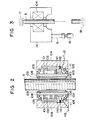
- FIG. 2 there is shown in longitudinal section a novel structure of the motor 1 which may be used with the system of FIG. 1.
- the structure includes a stator 101 constituted by a permanent magnet and a rotor 102 having a coil wound there- or, and mounted on a cylinder 103.
- the cylinder 103 is coupled with a fixed member 104 via a bearing 105 and thereby rotatably journaled on the member 104.
- a nut 106 is secured to the inner wall of the cylinder 103 and is rotated therewith.
- the feed screw 3 is shown in engagement with the nut 106 and is used to convert the rotation of the nut 106 into a linear movement.
- the coupling between the rotary cylinder 103 and the rotary nut 106 is formed with a pocket 108 filled with a pressure medium, e.g. oil or elastomeric material, for adjusting the coupling of these members.
- a screw 109 is threaded with the nut 1 06 and the cylinder 1 03 to adjustably compress the pressure medium in the pocket 108.
- Commutators 110 are secured to the outer wall of the cylinder 103 and ar ? positioned in contact with brushes 111 urged thereagainst under the pressure produced by springe 112 and energized from terminals respectively, with a motor drive signal produced by the system of FIG. 1.
- FIG. 3 shows in elevation an electrical machining (e.g. electrical discharge machining) arrangement for controlledly driving a tool head 14 to which a machining tool electrode 16 is secured via a supporting spindle 15, the head 14 being displaced vertically to move the tool electrode 16 towards and away from a workpiece (not shown) juxtaposed therewith across a machining gap.
- the fixed member 104 in FIG. 2 s secured to the tool head 14 and is linearly moved along the axis of the feed screw 3 when thenut 106 is rotated in the motor structure shown in FIG. 2.
- the feed screw 3 is shown supported between a pair of fixed positions 17 and 18 so as to be held against linear displacement.
Landscapes
- Engineering & Computer Science (AREA)
- Power Engineering (AREA)
- Human Computer Interaction (AREA)
- Manufacturing & Machinery (AREA)
- Physics & Mathematics (AREA)
- General Physics & Mathematics (AREA)
- Automation & Control Theory (AREA)
- Control Of Position Or Direction (AREA)
- Control Of Electric Motors In General (AREA)
Applications Claiming Priority (2)
| Application Number | Priority Date | Filing Date | Title |
|---|---|---|---|
| JP11659/80 | 1980-02-01 | ||
| JP1165980A JPS56110491A (en) | 1980-02-01 | 1980-02-01 | Controller for driving of motor |
Publications (2)
| Publication Number | Publication Date |
|---|---|
| EP0034033A1 true EP0034033A1 (de) | 1981-08-19 |
| EP0034033B1 EP0034033B1 (de) | 1985-11-27 |
Family
ID=11784097
Family Applications (1)
| Application Number | Title | Priority Date | Filing Date |
|---|---|---|---|
| EP81300432A Expired EP0034033B1 (de) | 1980-02-01 | 1981-02-02 | Regelung eines elektrischen Motorantriebssystems |
Country Status (3)
| Country | Link |
|---|---|
| EP (1) | EP0034033B1 (de) |
| JP (1) | JPS56110491A (de) |
| DE (1) | DE3173043D1 (de) |
Cited By (1)
| Publication number | Priority date | Publication date | Assignee | Title |
|---|---|---|---|---|
| EP0189794A3 (en) * | 1985-01-30 | 1987-04-01 | International Business Machines Corporation | Electromagnetic actuator system |
Families Citing this family (1)
| Publication number | Priority date | Publication date | Assignee | Title |
|---|---|---|---|---|
| JPS5989590A (ja) * | 1982-11-11 | 1984-05-23 | Brother Ind Ltd | モ−タの速度制御におけるpwm制御装置 |
Citations (1)
| Publication number | Priority date | Publication date | Assignee | Title |
|---|---|---|---|---|
| US4129813A (en) * | 1977-07-26 | 1978-12-12 | The Singer Company | Method and apparatus for adaptive control of a stepper motor |
Family Cites Families (7)
| Publication number | Priority date | Publication date | Assignee | Title |
|---|---|---|---|---|
| DE6913145U (de) * | 1969-04-01 | 1969-08-28 | Froriep Gmbh Maschf | Werkzeugmaschine mit konzentrischen spindeln |
| DE2532432C2 (de) * | 1975-07-19 | 1985-01-31 | Croon & Lucke Maschinenfabrik Gmbh + Co Kg, 7947 Mengen | Vorrichtung an einer Knäuelwickelmaschine zum Aufbringen von ringstreifenförmigen Banderolen |
| US4153863A (en) * | 1977-04-20 | 1979-05-08 | Colt Industries Operating Corp. (Pratt & Whitney Machine Tool Division) | DC Motor controller |
| JPS548817A (en) * | 1977-06-22 | 1979-01-23 | Hitachi Ltd | Digital controller for motor |
| US4115859A (en) * | 1977-06-30 | 1978-09-19 | Dynamics Research Corporation | Back gauge controller |
| US4194144A (en) * | 1977-07-05 | 1980-03-18 | Ncr Corporation | Constant velocity driving means |
| JPS5927013B2 (ja) * | 1977-08-05 | 1984-07-03 | 富士通株式会社 | 磁気テ−プ送りモ−タの速度制御方式 |
-
1980
- 1980-02-01 JP JP1165980A patent/JPS56110491A/ja active Pending
-
1981
- 1981-02-02 EP EP81300432A patent/EP0034033B1/de not_active Expired
- 1981-02-02 DE DE8181300432T patent/DE3173043D1/de not_active Expired
Patent Citations (1)
| Publication number | Priority date | Publication date | Assignee | Title |
|---|---|---|---|---|
| US4129813A (en) * | 1977-07-26 | 1978-12-12 | The Singer Company | Method and apparatus for adaptive control of a stepper motor |
Non-Patent Citations (2)
| Title |
|---|
| DESIGN ENGINEERING, Vol. 51, No. 4 April 1980, London, GB "New AC servo provides precise control of slide motions", pages 13, 14 * Pages 13, 14; figure 1 * * |
| ELEKTRIE, Vol. 32, No. 5, 1978, Berlin, DD U. RIEFENSTAHL: "Einsatz von Mikrorechnern zur Steuerung und Regelung elektrischer Antriebssysteme", pages 245-248 * Page 247, right-hand column, line 2 - page 248, left-hand column, line 36; figures 7,10 * * |
Cited By (1)
| Publication number | Priority date | Publication date | Assignee | Title |
|---|---|---|---|---|
| EP0189794A3 (en) * | 1985-01-30 | 1987-04-01 | International Business Machines Corporation | Electromagnetic actuator system |
Also Published As
| Publication number | Publication date |
|---|---|
| EP0034033B1 (de) | 1985-11-27 |
| JPS56110491A (en) | 1981-09-01 |
| DE3173043D1 (en) | 1986-01-09 |
Similar Documents
| Publication | Publication Date | Title |
|---|---|---|
| US4368412A (en) | Microprocessor-controlled motor drive control system | |
| EP0460224B1 (de) | Verfahren zur steuerung eines servomotors | |
| EP0423357B1 (de) | Anordnung zur regelung eines servomotors | |
| JP2709190B2 (ja) | 押し付け成形機の押し付けローラの周回軌道運動を制御する方法及びこの方法を実施するための押し付け成形機 | |
| EP0248071B1 (de) | Honmaschine | |
| US4471443A (en) | Compensation method and apparatus for thermal displacement | |
| EP0018710B1 (de) | Verfahren zum Bearbeiten eines Werkstücks und Vorrichtung zum Steuern des Vorschubs eines Schneidewerkzeugs | |
| US4379987A (en) | Spindle rotation control system | |
| US4374350A (en) | Control system for stopping spindle at predetermined rotational position | |
| EP0034033A1 (de) | Regelung eines elektrischen Motorantriebssystems | |
| EP0480350B1 (de) | Spritzgiessmaschine mit Steuermittel für den Antrieb der Schnecke | |
| US4041268A (en) | Method for adjusting the eccentricity of a spark-erosion machining electrode endowed with a movement of circular translation and a device for the application of said method | |
| US4527034A (en) | Electrode positioning method and apparatus for NC-EDM | |
| EP0245522B1 (de) | Dosierungsvorrichtung für einspritzgiessvorrichtung | |
| US4464866A (en) | Control system for finish grinding methods and apparatus | |
| US4623772A (en) | Apparatus and method for EDM polishing | |
| US4492061A (en) | Control system for grinding apparatus | |
| US4488029A (en) | Electro-erosive processing apparatus | |
| SU1415151A1 (ru) | Способ измерени износа режущего инструмента | |
| JP3262907B2 (ja) | 巻取り制御方法 | |
| JPH03245969A (ja) | トラバース研削方法 | |
| KR100238982B1 (ko) | 나사절삭가공장치 및 그 제어방법 | |
| SU1299705A1 (ru) | Способ контрол момента касани инструментом детали | |
| KR960015955B1 (ko) | 방전 펄스 제어장치 및 그 제어방법 | |
| JPH0293713A (ja) | 位置決め装置 |
Legal Events
| Date | Code | Title | Description |
|---|---|---|---|
| PUAI | Public reference made under article 153(3) epc to a published international application that has entered the european phase |
Free format text: ORIGINAL CODE: 0009012 |
|
| AK | Designated contracting states |
Designated state(s): DE FR GB IT |
|
| ITCL | It: translation for ep claims filed |
Representative=s name: DR. ING. A. RACHELI & C. |
|
| 17P | Request for examination filed |
Effective date: 19810814 |
|
| DET | De: translation of patent claims | ||
| ITF | It: translation for a ep patent filed | ||
| GRAA | (expected) grant |
Free format text: ORIGINAL CODE: 0009210 |
|
| AK | Designated contracting states |
Designated state(s): DE FR GB IT |
|
| REF | Corresponds to: |
Ref document number: 3173043 Country of ref document: DE Date of ref document: 19860109 |
|
| ET | Fr: translation filed | ||
| PLBE | No opposition filed within time limit |
Free format text: ORIGINAL CODE: 0009261 |
|
| STAA | Information on the status of an ep patent application or granted ep patent |
Free format text: STATUS: NO OPPOSITION FILED WITHIN TIME LIMIT |
|
| 26N | No opposition filed | ||
| PGFP | Annual fee paid to national office [announced via postgrant information from national office to epo] |
Ref country code: FR Payment date: 19900228 Year of fee payment: 10 |
|
| ITTA | It: last paid annual fee | ||
| PG25 | Lapsed in a contracting state [announced via postgrant information from national office to epo] |
Ref country code: FR Effective date: 19911031 |
|
| REG | Reference to a national code |
Ref country code: FR Ref legal event code: ST |
|
| PGFP | Annual fee paid to national office [announced via postgrant information from national office to epo] |
Ref country code: DE Payment date: 19990205 Year of fee payment: 19 |
|
| PGFP | Annual fee paid to national office [announced via postgrant information from national office to epo] |
Ref country code: GB Payment date: 20000121 Year of fee payment: 20 |
|
| PG25 | Lapsed in a contracting state [announced via postgrant information from national office to epo] |
Ref country code: DE Free format text: LAPSE BECAUSE OF NON-PAYMENT OF DUE FEES Effective date: 20001201 |
|
| PG25 | Lapsed in a contracting state [announced via postgrant information from national office to epo] |
Ref country code: GB Free format text: LAPSE BECAUSE OF EXPIRATION OF PROTECTION Effective date: 20010201 |
|
| REG | Reference to a national code |
Ref country code: GB Ref legal event code: PE20 Effective date: 20010201 |