EP0033992A2 - Masonry guide - Google Patents
Masonry guide Download PDFInfo
- Publication number
- EP0033992A2 EP0033992A2 EP81200124A EP81200124A EP0033992A2 EP 0033992 A2 EP0033992 A2 EP 0033992A2 EP 81200124 A EP81200124 A EP 81200124A EP 81200124 A EP81200124 A EP 81200124A EP 0033992 A2 EP0033992 A2 EP 0033992A2
- Authority
- EP
- European Patent Office
- Prior art keywords
- guide
- masonry
- masonry guide
- tubular
- guide member
- Prior art date
- Legal status (The legal status is an assumption and is not a legal conclusion. Google has not performed a legal analysis and makes no representation as to the accuracy of the status listed.)
- Withdrawn
Links
Images


Classifications
-
- E—FIXED CONSTRUCTIONS
- E04—BUILDING
- E04G—SCAFFOLDING; FORMS; SHUTTERING; BUILDING IMPLEMENTS OR AIDS, OR THEIR USE; HANDLING BUILDING MATERIALS ON THE SITE; REPAIRING, BREAKING-UP OR OTHER WORK ON EXISTING BUILDINGS
- E04G21/00—Preparing, conveying, or working-up building materials or building elements in situ; Other devices or measures for constructional work
- E04G21/14—Conveying or assembling building elements
- E04G21/16—Tools or apparatus
- E04G21/18—Adjusting tools; Templates
- E04G21/1808—Holders for bricklayers' lines, bricklayers' bars; Sloping braces
-
- E—FIXED CONSTRUCTIONS
- E04—BUILDING
- E04G—SCAFFOLDING; FORMS; SHUTTERING; BUILDING IMPLEMENTS OR AIDS, OR THEIR USE; HANDLING BUILDING MATERIALS ON THE SITE; REPAIRING, BREAKING-UP OR OTHER WORK ON EXISTING BUILDINGS
- E04G21/00—Preparing, conveying, or working-up building materials or building elements in situ; Other devices or measures for constructional work
- E04G21/14—Conveying or assembling building elements
- E04G21/16—Tools or apparatus
- E04G21/18—Adjusting tools; Templates
Definitions
- the invention relates to a masonry guide.
- a masonry guide is defined as a wooden beam or upright which, in the upright position, is a useful aid in laying brick walls to obtain a straight bond between the successive brick courses.
- the masonry guide which is kept in plumb by two braces set up in two directions, is provided with pencil markings for a division of the successive course thicknesses of a brick with joint.
- a masonry guide is used for only a limited number of times, so as to avoid inadvertent use of the pencils markings for a different application. This must be regarded as a first disadventage of the existing masonry guides.
- a second disadventage of the existing masonry guides is that the wooden guides are liable to warping, especially under wet and hot weather conditions.
- these masonry guides are of a fixed length, giving rise to problems in building up walls of greater height; this involves the use of a following beam or upright to be placed straight on the existing beam or upright and to be secured by braces. In the building trade such work is found to be troublesome and must be noted as a third disadventage.
- a fourth disadventage of the existing masonry guides also concerns the fixed length of the guides: If in laying a brick wall of small height the masonry guide is too long, a part thereof must be sawn off; this will be damaging to the durability of the guide.
- the present inventoin has for its object to provide a solution for the above disadventages.
- the masonry guide is characterized by a tubular guide member having an extension piece of smaller cross section made of durable, undeformable material, which tubular guide member comprises means for fitting bracing means with respect to the bearing face of the masonry guide, and which extension piece, qua cross section, is suitable for a tight, slidable fit in a similar guide member as attachment to the masonry guide.
- the masonry guide according to the invention is a useful and labour-saving aid in the building trade.
- Fig. 1 shows a section of a masonry guide, which is denoted by the numeral 1.
- Guide 1 comprises a tubular guide member 2 and an extension piece 3 of smaller cross section. Both the tubular guide member 2 and the extension piece 3 are of rectangular cross section and of such dimensions that the hollow core of member 2 permits a tight fit of extension piece 3 into member 2.
- Guide member 2 is made of durable, undeformable, non-nailable material, which could be of various metals (e.g. aluminium ) or synthetic material (e.g. polyvinyl chloride).
- Extension piece 3, which may consist of a solid block, can be made of the above material, but also of hardwood.
- extension piece 3 is made of hardwood, it can be nailed or tacked directly to the bottom surface of the wall to be erected; thereafter the masonry guide must be set plumb.
- a footing 4 consists of a baseplate 5 supporting in one corner a tubular guide member 6 whose cross section corresponds with that of masonry guide 1. In this way, masonry guide 1 is directly set upright by placing extension piece 3 in guide member 6; after one man has placed all footings 4 and accompanying masonry guides 1 in the desired position, these guides can be braced.
- the material of which the masonry guides are made is however unsuitable for nailing a brace thereto.
- at least two sides of masonry guide 1 contain one or several holes 7 at one or several levels, and the space behind it is filled with nailable material, preferably a softwood.
- nailable material preferably a softwood.
- braces 8 of the masonry guide 1 Apart from securing the braces 8 of the masonry guide 1 in this way, it is also possible to attach them to the masonry guide 1 by a hinged connection at end 9, as shown in Fig. 2. In such a case, the other end 10 of braces 8can be secured to the bottom by conventional means.
- a favourable embodiment of a masonry guide 1 fitted with hinged bracing means is obtained when the length of the braces is adjustable; this is achieved by bracing means consisting of two telescoping members 11 and 12 with screwed securing means 13.
- Another embodiment of adjustable bracing means 8 is obtained by incorporating screw-mounted members (such as a turnbuckle ) in the bracing means 8.
- the nailable elements in the masonry guide 1 should be secured in guide member 2 by a screwed connection 14, since these elements after being in use for some time need to be replaced.
- extension 14 also consists of a tubular guide member 15 having an extension piece 16 of smaller cross-section made of a durable undeformable material. Since guide member 15 of extension 14 is of the same section as the masonry guide 1 and extension piece 16 corresponds to the internal dimensions of guide member 15 used for extension 14, extension piece 16 will make a tight, detachable fit with guide member 15 of masonry guide 1. Similarly, masonry guide 1 can be lengthened simply with a plurality of extensions 14. The provisions of a diversity in the length of extensions 14 enables to obtain practically any desired length for the masonry guide 1.
- a self-tensioning, line-adjusting means 18 slidable on the masonry guide is employed.
- means 18 consists of a mounting plate, bent over three ribs of the masonry guide, and a line clamp 19, which can be fitted as a sliding cap or mounting clip and is slidable on the masonry guide 1. This sliding motion is not spontaneous, owing to the damping and frictional engagement of mounting plate 18 with masonry guide 1.
- the mounting plate 18 cannot be bent over more than three ribs, because it is never to cover the recesses 7 for the braces 8.
- the required spacing lines can be marked on masonry guide 1 by pencil 1; the kind of material permits easy removal of these lines.
- Line clamp 19 on the mounting plate to take up the guide line may be of different designs, e.g. a cleat.
- Means 17 comprises a U-shaped mounting plate with short legs 20 and 21. This plate is preferably made of spring steel to obtain a self-clamping fixture on the tubular guide member 2.
- Leg 20 contains a hole 22, through which guide line 17, passed around rib 23 of guide member 2, is guided along the inner side of leg 20, the recess 22 and the outer side of means 17 to the line clamp 19.
- top piece 24 of adjustable length to be placed on the upper tubular member, permitting the entire combination of masonry guide and attachments to be used between ceilings for the construction of tunnels or renovation work.
- a top piece (see Fig.6) comprises a block-shaped member 25 with an enlarged cover plate 26, preventing that with the insertion of member 25 into the opening of the upper tubular guide member 2 the entire top piece would fall into this opening.
- Top piece 24 further comprises an adjusting plate or head plate 27.
- This plate is adjustable in height by a screwed spindle 28 and can be set, within a certain range, to any desired distance from cover plate 26, while member 25 is secured in place by a locking pin 29 in a tubular end.
- a screwed spindle 28 thereby engages firmly in the block-shaped member 25 of top piece 24.
- Member 25 may be made of a durable material.
- a spacing attachment 30 for maintaining a certain distance between two masonry guides 1 to place, after laying the bricks, a door case in the opening between the two wall parts.
- a spacing attachment may consist of a tubular or U-shaped guide member 31 having a U-shaped head support 32 at each end.
- Attachment 30 also comprises length-adjusting means, containing telescoping members 33 and 34. These members are interlocked by a locking pin 35.
- Each of the head supports 32 are fitted with a hooked projecting part 36 which hooks in holes provided in masonry guide 1.
- Member 33 need not consist of two parts made of different guide members, as shown in Fig.7; it may also be made of one single guide member.
Landscapes
- Engineering & Computer Science (AREA)
- Architecture (AREA)
- Mechanical Engineering (AREA)
- Civil Engineering (AREA)
- Structural Engineering (AREA)
- Joining Of Building Structures In Genera (AREA)
- Retaining Walls (AREA)
Abstract
A masonry guide 1 for use in laying brick walls to obtain a straight bond between the successive brick courses. The masonry guide 1 comprises at least a tubular guide member 2 having an extension piece 3 of smaller cross section made of durable undeformable material, which tubular guide member 2 comprises means for fitting bracing means 8 with respect to the bearing face of the guide member 1, and which extension piece 3, qua cross section, is suitable for a tight, slidable fit in a similar guide member 6 as attachment to the masonry guide 1. In a preferred embodiment, the above means is formed by at least one hole or recess 7 in the tubular wall of the masonry guide 1 in combination with the insertion of nailable material inside the masonry guide 1 at the location of such a recess 7.
Description
- The invention relates to a masonry guide.
- Up to now, a masonry guide is defined as a wooden beam or upright which, in the upright position, is a useful aid in laying brick walls to obtain a straight bond between the successive brick courses. The masonry guide, which is kept in plumb by two braces set up in two directions, is provided with pencil markings for a division of the successive course thicknesses of a brick with joint.
- Since the pencil markings on the wood are difficult to erase, a masonry guide is used for only a limited number of times, so as to avoid inadvertent use of the pencils markings for a different application. This must be regarded as a first disadventage of the existing masonry guides.
- A second disadventage of the existing masonry guides is that the wooden guides are liable to warping, especially under wet and hot weather conditions.
- Furthermore, these masonry guides are of a fixed length, giving rise to problems in building up walls of greater height; this involves the use of a following beam or upright to be placed straight on the existing beam or upright and to be secured by braces. In the building trade such work is found to be troublesome and must be noted as a third disadventage.
- A fourth disadventage of the existing masonry guides also concerns the fixed length of the guides: If in laying a brick wall of small height the masonry guide is too long, a part thereof must be sawn off; this will be damaging to the durability of the guide.
- The present inventoin has for its object to provide a solution for the above disadventages.
- According to the invention, the masonry guide is characterized by a tubular guide member having an extension piece of smaller cross section made of durable, undeformable material, which tubular guide member comprises means for fitting bracing means with respect to the bearing face of the masonry guide, and which extension piece, qua cross section, is suitable for a tight, slidable fit in a similar guide member as attachment to the masonry guide.
- Just in combination with a number of attachments ! described hereinafter, the masonry guide according to the invention is a useful and labour-saving aid in the building trade.
- The invention and its applications will now be described with reference to the accompanying figures, of which:
- Fig. 1 illustrates an embodiment of a masonry guide according to the invention;
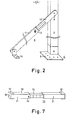
- Fig. 2 illustrates an embodiment of a masonry guide with bracing means attached;
- Fig. 3 is a first attachment to a masonry guide according to the invention;
- Fig. 4 and 5 are two embodiments of a second attachment to a masonry guide according to the invention;
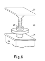
- Fig. 6 is a third attachment to a masonry guide according to the invention; and
- Fig. 7 is a fourth attachment to a masonry guide according to the invention.
- Fig. 1 shows a section of a masonry guide, which is denoted by the
numeral 1.Guide 1 comprises atubular guide member 2 and anextension piece 3 of smaller cross section. Both thetubular guide member 2 and theextension piece 3 are of rectangular cross section and of such dimensions that the hollow core ofmember 2 permits a tight fit ofextension piece 3 intomember 2.Guide member 2 is made of durable, undeformable, non-nailable material, which could be of various metals ( e.g. aluminium ) or synthetic material ( e.g. polyvinyl chloride).Extension piece 3, Which may consist of a solid block, can be made of the above material, but also of hardwood. - If
extension piece 3 is made of hardwood, it can be nailed or tacked directly to the bottom surface of the wall to be erected; thereafter the masonry guide must be set plumb. Instead of a direct nail fixture to the floor, it is possible to position the masonry guide on the floor by an attachment,viz. afooting 4. Such a footing consists of abaseplate 5 supporting in one corner atubular guide member 6 whose cross section corresponds with that ofmasonry guide 1. In this way,masonry guide 1 is directly set upright by placingextension piece 3 inguide member 6; after one man has placed allfootings 4 and accompanyingmasonry guides 1 in the desired position, these guides can be braced. - The material of which the masonry guides are made is however unsuitable for nailing a brace thereto. To overcome this problem, at least two sides of
masonry guide 1 contain one orseveral holes 7 at one or several levels, and the space behind it is filled with nailable material, preferably a softwood. Hence, one end of thebraces 8 can be nailed tomasonry guide 1 and the other end secured to the bottom in a similar way. - Apart from securing the
braces 8 of themasonry guide 1 in this way, it is also possible to attach them to themasonry guide 1 by a hinged connection atend 9, as shown in Fig. 2. In such a case, theother end 10 of braces 8can be secured to the bottom by conventional means. A favourable embodiment of amasonry guide 1 fitted with hinged bracing means is obtained when the length of the braces is adjustable; this is achieved by bracing means consisting of twotelescoping members - The nailable elements in the
masonry guide 1 should be secured inguide member 2 by ascrewed connection 14, since these elements after being in use for some time need to be replaced. - The disadventage of cutting long masonry guides down to short lengths is obviated by keeping the masonry guide according to the invention rather short and by extending it, if required, with
extensions 14, eliminating cumbersome and time-consuming positioning, see Fig.3. Using the masonry guide in question, this is achieved when the extension also consists of atubular guide member 15 having anextension piece 16 of smaller cross-section made of a durable undeformable material. Sinceguide member 15 ofextension 14 is of the same section as themasonry guide 1 andextension piece 16 corresponds to the internal dimensions ofguide member 15 used forextension 14,extension piece 16 will make a tight, detachable fit withguide member 15 ofmasonry guide 1. Similarly,masonry guide 1 can be lengthened simply with a plurality ofextensions 14. The provisions of a diversity in the length ofextensions 14 enables to obtain practically any desired length for themasonry guide 1. - To attach, at a desired heigth, a
guide line 17 tomasonry guide 1 or to anextension 14 placed thereon, a self-tensioning, line-adjusting means 18 slidable on the masonry guide is employed. In a first embodiment (see Fig.4), means 18 consists of a mounting plate, bent over three ribs of the masonry guide, and aline clamp 19, which can be fitted as a sliding cap or mounting clip and is slidable on themasonry guide 1. This sliding motion is not spontaneous, owing to the damping and frictional engagement of mounting plate 18 withmasonry guide 1. The mounting plate 18 cannot be bent over more than three ribs, because it is never to cover therecesses 7 for thebraces 8. - The required spacing lines can be marked on
masonry guide 1 bypencil 1; the kind of material permits easy removal of these lines.Line clamp 19 on the mounting plate to take up the guide line may be of different designs, e.g. a cleat. - A second embodiment of a line-adjusting means 17 is shown in Fig.5.
Means 17 comprises a U-shaped mounting plate withshort legs tubular guide member 2.Leg 20 contains ahole 22, through whichguide line 17, passed aroundrib 23 ofguide member 2, is guided along the inner side ofleg 20, therecess 22 and the outer side ofmeans 17 to theline clamp 19. - The above-described masonry guide, which can be lengthened with one or
several extensions 14, is also suitable for supporting atop piece 24 of adjustable length to be placed on the upper tubular member, permitting the entire combination of masonry guide and attachments to be used between ceilings for the construction of tunnels or renovation work. Such a top piece (see Fig.6) comprises a block-shaped member 25 with an enlargedcover plate 26, preventing that with the insertion ofmember 25 into the opening of the uppertubular guide member 2 the entire top piece would fall into this opening.Top piece 24 further comprises an adjusting plate orhead plate 27. This plate is adjustable in height by ascrewed spindle 28 and can be set, within a certain range, to any desired distance fromcover plate 26, whilemember 25 is secured in place by alocking pin 29 in a tubular end. In this way the use of "k a masonry guide 1 on afooting 4, in combination with one orseveral extensions 14 and atop piece 24, enables to adjust the whole arrangement to the required ceiling height and therewith to function as propping means in tunnelling and/or renovation work. Thescrewed spindle 28 thereby engages firmly in the block-shaped member 25 oftop piece 24.Member 25 may be made of a durable material. - Another attachment for
masonry guide 1 is a spacing attachment 30 (see Fig.7) for maintaining a certain distance between twomasonry guides 1 to place, after laying the bricks, a door case in the opening between the two wall parts. Such a spacing attachment may consist of a tubular or U-shapedguide member 31 having aU-shaped head support 32 at each end.Attachment 30 also comprises length-adjusting means, containingtelescoping members locking pin 35. Each of thehead supports 32 are fitted with a hooked projectingpart 36 which hooks in holes provided inmasonry guide 1.Member 33 need not consist of two parts made of different guide members, as shown in Fig.7; it may also be made of one single guide member. - Besides a masonry guide with separate attachments, it is also possible to construct a fixed assembly of a masonry guide together with one or several means whose functions are as described above. In such a case, the extension piece of a smaller.cross section, as used with the separate attachments, can be omitted.
Claims (16)
1. Masonry guide characterized by a tubular guide member having an extension piece of smaller cross section made of durable, undeformable material, which tubular guide member comprises means for fitting bracing means with respect to the bearing face of the masonry guide, and which extension piece,qua cross section, is suitable for a tight, slidable fit in a similar guide member as attachment to the masonry guide.
2. Masonry guide as claimed in claim 1, characterized in that the extension piece comprises a block-shaped member of nailable material partially accommodated in said tubular guide member.
3. Masonry guide as claimed in claim 1, characterized in that said means is formed by at least one recess fitted in the tubular wall of the masonry guide in combination with the insertion of nailable material inside the masonry guide at the location of such a recess.
4. Masonry guide as claimed in claim 1, characterized in that said means comprises supporting means adjustable in length, which supporting means is attached by a hinged connection to said tubular guide member and by a nailed connection to said bearing face.
5. Masonry guide as claimed in claim 4, characterized in that said supporting means comprises telescoping members with screwed securing means.
6. Nailable base-plate for a masonry guide, as claimed in claim 1, which base-plate comprises tubular extension means for attaining said tight, slidable fit of the extension piece of the masonry guide.
7. Extension means for a masonry guide, as claimed in claim 1, which extension neans comprises a tubular guide member with an extension piece of smaller cross section made of durable, undeformable material, which extension piece, qua cross section, is suitable for a tight, slidable fit in a guide member of similar shape attached to the masonry guide.
8. Toppiece for a guide member attached to the masonry guide, as claimed in claim 1 or 7, which top piece comprises a fitting piece for attaining a tight, slidable fit in a guide member attached to the masonry guide, and an adjusting plate with screwed spindle means.
9. Masonry guide line means for a guide member attached to the masonry guide, as claimed in claim 1 or 7, which guide line means comprises a sliding cap fitted on the outer side of the masonry guide, which sliding cap is provided with securing means for a masonry guide line.
10. Masonry guide line means as claimed in claim 9, characterized in that said sliding cap comprises a plate member bent over three ribs of the tubular guide member.
11. Masonry guide line means as claimed in claim 9, characterized in that said sliding cap comprises a spring-steel plate member bent over two ribs of the masonry guide, which spring-steel member contains a hole at one of the ends, through which hole a guide line, passed along the inner side of said sliding cap, is guided to said securing means fitted on the outer side of the sliding cap.
12. spacing attachment for maintaining a certain distance between two guide members attached to different masonry guides, as claimed in claim 1 or 7, which spacing attachment comprises length-adjusting means and at each end a U-shaped head support to be pressed on a tubular guide member.
13. Masonry guide characterized by a tubular guide member having a nailable-base plate of durable, undeformable material, which tubular guide member comprises means for fitting bracing means with respect to the bearing face of the masonry guide.
14. Masonry guide as claimed in claim 13, characterized in that said means consists of at least one recess provided in the tubular wall of the masonry guide in combination with the insertion of nailable material inside the guide member at the location of such a recess.
15. Masonry guide as claimed in claim 13, characterized in that said means comprises a supporting member adjustable in length, which supporting member is attached by a hinged connection to the guide member and by a nailed connection to said bearing face.
16. Masonry guide as claimed in claim 1, 13, 14 or 15, characterized in that the masonry guide comprises a top piece having an adjustable plate with screwed spindle means.
Applications Claiming Priority (2)
| Application Number | Priority Date | Filing Date | Title |
|---|---|---|---|
| NL8000783A NL181593C (en) | 1980-02-07 | 1980-02-07 | TUBULAR MASONIC PROFILE. |
| NL8000783 | 1980-02-07 |
Publications (2)
| Publication Number | Publication Date |
|---|---|
| EP0033992A2 true EP0033992A2 (en) | 1981-08-19 |
| EP0033992A3 EP0033992A3 (en) | 1982-02-03 |
Family
ID=19834799
Family Applications (1)
| Application Number | Title | Priority Date | Filing Date |
|---|---|---|---|
| EP81200124A Withdrawn EP0033992A3 (en) | 1980-02-07 | 1981-02-03 | Masonry guide |
Country Status (2)
| Country | Link |
|---|---|
| EP (1) | EP0033992A3 (en) |
| NL (1) | NL181593C (en) |
Cited By (9)
| Publication number | Priority date | Publication date | Assignee | Title |
|---|---|---|---|---|
| GB2158863A (en) * | 1984-05-19 | 1985-11-20 | Raymond Arthur Reeves | Device for supporting a building line reference |
| NL8502146A (en) * | 1985-07-29 | 1987-02-16 | Adrianus Marinus Van Heugten | Setting beam for brick wall erection - has bottom grip and hinging adjustable-length supporting bars |
| EP0416690A3 (en) * | 1989-09-05 | 1991-09-18 | Adrianus Johannes Leonardus Marinus Bekkers | Mason's adjusting profile |
| EP0500158A1 (en) * | 1991-02-18 | 1992-08-26 | Compri-Aluminium B.V. | Mason's profile |
| NL1017419C2 (en) * | 2001-02-21 | 2002-08-22 | Adriaan Johan Van De Wal | System for positioning upright component, has positioning devices comprising elongated tension unit clamp able between floor and ceiling, and coupling components for coupling upright component to tension unit |
| CN102061809A (en) * | 2010-12-29 | 2011-05-18 | 王道利 | Anti-deviation device for building wall |
| FR2985532A1 (en) * | 2012-01-06 | 2013-07-12 | Robert Bazin | DEVICE FOR ASSISTANCE OF A MACON TO OBTAIN THE VERTICALITY OF WALLS WHEN BUILDING MACON WALLS |
| WO2015120514A1 (en) * | 2014-02-15 | 2015-08-20 | Ardagh Martin William Irvine | Profile apparatus, profile system and associated methods |
| CN112502446A (en) * | 2020-11-03 | 2021-03-16 | 中国一冶集团有限公司 | Socket type center barrel temporary support and using method thereof |
Family Cites Families (5)
| Publication number | Priority date | Publication date | Assignee | Title |
|---|---|---|---|---|
| BE620282A (en) * | ||||
| BE646876A (en) * | ||||
| US2623289A (en) * | 1949-07-18 | 1952-12-30 | Kampel Everett | Guideline supporting apparatus for bricklaying |
| US3096588A (en) * | 1959-06-22 | 1963-07-09 | Paul R Cook | Masonry guide apparatus |
| AT311025B (en) * | 1971-10-04 | 1973-10-25 | Grohmann Kg Geb | Assembly frame for setting up wall elements, in particular large-area partition wall elements with and without wall opening linings |
-
1980
- 1980-02-07 NL NL8000783A patent/NL181593C/en not_active IP Right Cessation
-
1981
- 1981-02-03 EP EP81200124A patent/EP0033992A3/en not_active Withdrawn
Cited By (12)
| Publication number | Priority date | Publication date | Assignee | Title |
|---|---|---|---|---|
| GB2158863A (en) * | 1984-05-19 | 1985-11-20 | Raymond Arthur Reeves | Device for supporting a building line reference |
| EP0162560A3 (en) * | 1984-05-19 | 1986-12-03 | Raymond Arthur Reeves | Device for supporting a building line reference |
| NL8502146A (en) * | 1985-07-29 | 1987-02-16 | Adrianus Marinus Van Heugten | Setting beam for brick wall erection - has bottom grip and hinging adjustable-length supporting bars |
| EP0416690A3 (en) * | 1989-09-05 | 1991-09-18 | Adrianus Johannes Leonardus Marinus Bekkers | Mason's adjusting profile |
| EP0500158A1 (en) * | 1991-02-18 | 1992-08-26 | Compri-Aluminium B.V. | Mason's profile |
| NL1017419C2 (en) * | 2001-02-21 | 2002-08-22 | Adriaan Johan Van De Wal | System for positioning upright component, has positioning devices comprising elongated tension unit clamp able between floor and ceiling, and coupling components for coupling upright component to tension unit |
| CN102061809A (en) * | 2010-12-29 | 2011-05-18 | 王道利 | Anti-deviation device for building wall |
| CN102061809B (en) * | 2010-12-29 | 2012-10-24 | 王道利 | Anti-deviation device for building wall |
| FR2985532A1 (en) * | 2012-01-06 | 2013-07-12 | Robert Bazin | DEVICE FOR ASSISTANCE OF A MACON TO OBTAIN THE VERTICALITY OF WALLS WHEN BUILDING MACON WALLS |
| FR2985531A1 (en) * | 2012-01-06 | 2013-07-12 | Robert Bazin | Device for assisting mason in construction of vertical walls from e.g. agglos, has struts fixed on lower part of secondary shoes on ground, where struts are secured in upper part of metal brackets to ensure stabilization of vertical mast |
| WO2015120514A1 (en) * | 2014-02-15 | 2015-08-20 | Ardagh Martin William Irvine | Profile apparatus, profile system and associated methods |
| CN112502446A (en) * | 2020-11-03 | 2021-03-16 | 中国一冶集团有限公司 | Socket type center barrel temporary support and using method thereof |
Also Published As
| Publication number | Publication date |
|---|---|
| NL181593B (en) | 1987-04-16 |
| NL181593C (en) | 1989-12-18 |
| EP0033992A3 (en) | 1982-02-03 |
| NL8000783A (en) | 1981-09-01 |
Similar Documents
| Publication | Publication Date | Title |
|---|---|---|
| US3972168A (en) | Tying device for tying a wood framing structure to a masonry wall | |
| US2856646A (en) | Building brace | |
| US5570860A (en) | Gutter bracket | |
| US2365478A (en) | Wall clip | |
| EP0033992A2 (en) | Masonry guide | |
| US3456411A (en) | Ceiling tile system | |
| US4594818A (en) | Apparatus for attaching flashing to a roof | |
| US2216271A (en) | Shingle joiner or shingle-butt-end clip | |
| US6845594B2 (en) | Pre-manufactured joist and beam support for concrete walls | |
| US3127683A (en) | Universal mason's corner pole | |
| US3753328A (en) | Method of installing modular wall construction | |
| US3174256A (en) | Siding construction | |
| US5441125A (en) | Platform for temporary attachment to walls | |
| US1858715A (en) | Building construction | |
| CZ293610B6 (en) | Attachment fitting for longitudinally grooved cover strips | |
| US3060641A (en) | Siding construction | |
| KR200326563Y1 (en) | Mold combination member | |
| JPS626194Y2 (en) | ||
| JP6933472B2 (en) | Foundation packing | |
| KR960000706Y1 (en) | Ceiling fixing device | |
| JPS5916411Y2 (en) | S-shaped tiled steep slope roof | |
| JPH0124244Y2 (en) | ||
| JPS5838801Y2 (en) | Structure for attaching pillars to roofing materials | |
| US20070044419A1 (en) | Truss setting bracket | |
| JPS5835706Y2 (en) | Stair components on slopes |
Legal Events
| Date | Code | Title | Description |
|---|---|---|---|
| PUAI | Public reference made under article 153(3) epc to a published international application that has entered the european phase |
Free format text: ORIGINAL CODE: 0009012 |
|
| AK | Designated contracting states |
Designated state(s): AT BE CH DE FR GB LU NL |
|
| PUAL | Search report despatched |
Free format text: ORIGINAL CODE: 0009013 |
|
| AK | Designated contracting states |
Designated state(s): AT BE CH DE FR GB LU NL |
|
| STAA | Information on the status of an ep patent application or granted ep patent |
Free format text: STATUS: THE APPLICATION IS DEEMED TO BE WITHDRAWN |
|
| 18D | Application deemed to be withdrawn |
Effective date: 19830112 |