EP0033020B1 - Procédé et moyens pour le lancement et le gonflage d'un ballon spatial - Google Patents
Procédé et moyens pour le lancement et le gonflage d'un ballon spatial Download PDFInfo
- Publication number
- EP0033020B1 EP0033020B1 EP80201053A EP80201053A EP0033020B1 EP 0033020 B1 EP0033020 B1 EP 0033020B1 EP 80201053 A EP80201053 A EP 80201053A EP 80201053 A EP80201053 A EP 80201053A EP 0033020 B1 EP0033020 B1 EP 0033020B1
- Authority
- EP
- European Patent Office
- Prior art keywords
- balloon
- space
- carrier
- launching
- cable
- Prior art date
- Legal status (The legal status is an assumption and is not a legal conclusion. Google has not performed a legal analysis and makes no representation as to the accuracy of the status listed.)
- Expired
Links
- 238000000034 method Methods 0.000 title claims abstract description 30
- 238000000926 separation method Methods 0.000 claims abstract description 6
- 230000002787 reinforcement Effects 0.000 claims description 6
- 239000010408 film Substances 0.000 claims description 5
- 238000005520 cutting process Methods 0.000 claims description 3
- 230000002706 hydrostatic effect Effects 0.000 claims description 3
- 239000010409 thin film Substances 0.000 claims description 3
- 238000005304 joining Methods 0.000 claims description 2
- 230000001681 protective effect Effects 0.000 abstract description 3
- 230000001939 inductive effect Effects 0.000 abstract 1
- 238000007789 sealing Methods 0.000 abstract 1
- 239000007789 gas Substances 0.000 description 13
- 230000003014 reinforcing effect Effects 0.000 description 7
- 239000000463 material Substances 0.000 description 5
- 230000006866 deterioration Effects 0.000 description 4
- 239000004698 Polyethylene Substances 0.000 description 3
- 230000000903 blocking effect Effects 0.000 description 3
- 238000004519 manufacturing process Methods 0.000 description 3
- 210000000056 organ Anatomy 0.000 description 3
- -1 polyethylene Polymers 0.000 description 3
- 229920000573 polyethylene Polymers 0.000 description 3
- 238000009826 distribution Methods 0.000 description 2
- 230000000694 effects Effects 0.000 description 2
- 238000012550 audit Methods 0.000 description 1
- 230000005540 biological transmission Effects 0.000 description 1
- 230000007423 decrease Effects 0.000 description 1
- 238000010586 diagram Methods 0.000 description 1
- 230000000763 evoking effect Effects 0.000 description 1
- 239000002360 explosive Substances 0.000 description 1
- 230000002349 favourable effect Effects 0.000 description 1
- 238000010438 heat treatment Methods 0.000 description 1
- 239000001307 helium Substances 0.000 description 1
- 229910052734 helium Inorganic materials 0.000 description 1
- SWQJXJOGLNCZEY-UHFFFAOYSA-N helium atom Chemical compound [He] SWQJXJOGLNCZEY-UHFFFAOYSA-N 0.000 description 1
- 239000001257 hydrogen Substances 0.000 description 1
- 229910052739 hydrogen Inorganic materials 0.000 description 1
- 125000004435 hydrogen atom Chemical class [H]* 0.000 description 1
- 238000005259 measurement Methods 0.000 description 1
- 229920000728 polyester Polymers 0.000 description 1
- 229920006267 polyester film Polymers 0.000 description 1
- 210000001747 pupil Anatomy 0.000 description 1
Images


Classifications
-
- B—PERFORMING OPERATIONS; TRANSPORTING
- B64—AIRCRAFT; AVIATION; COSMONAUTICS
- B64B—LIGHTER-THAN AIR AIRCRAFT
- B64B1/00—Lighter-than-air aircraft
- B64B1/40—Balloons
Definitions
- the invention relates to a method of launching and inflating a space balloon carrying a load; it aims in particular to launch large-volume balloons for the exploration of the high stratospheric layers.
- the invention extends to a carrier balloon allowing the implementation of this launching process.
- the balloon meets very severe conditions, on the one hand, during the crossing of the low layers of high densities, which are the seat of significant turbulence, on the other hand, during the crossing of the tropopause which corresponds to the coldest zone of the atmosphere (- 70 ° to - 80 ° C) and is the seat of horizontal currents with very high speed gradient.
- the expansion of the balloon is still small and the forces exerted on it are supported by a reduced surface area of the envelope, which conditions high stresses per unit area.
- the low temperatures lead to embrittlement of the envelope material which becomes little able to withstand the stresses due to the speed gradient; these constraints generate shear effects all the stronger as the balloon has a large volume.
- launching techniques which use an auxiliary launching bubble so as to reduce the inflation difficulties on the ground of the main balloon (patent FR-A-2132569).
- auxiliary launching bubble so as to reduce the inflation difficulties on the ground of the main balloon.
- the envelope of the ball supports all the load and is subjected to high stresses as in the traditional process evoked previously (where the main ball is launched alone).
- the present invention proposes to provide a solution to the problems mentioned above and to allow space balloons to reach the stratospheric layers to be explored without risk of deterioration.
- the invention proposes to indicate a new method of launching and inflating a space balloon, making it possible to considerably reduce the stresses which are exerted on its envelope, in particular during the crossing of the low layers and the tropopause.
- the last three operations (closing the sleeve, separating the balloons and blocking the lower pole of the space balloon) can be executed successively in a predetermined order or almost simultaneously at a given altitude.
- the space balloon is housed, in the deflated state, in a protective sheath having a generator of least resistance authorizing the rupture of said sheath during inflation of the balloon.
- an auxiliary support balloon of small dimensions which drives the space balloon in the lower layers and the tropopause in the fully folded state, (preferably protected by a sheath), the envelope of said space balloon not supporting, during the ascent , that its own weight since the load is attached to the axial link of said balloon, which is connected to the axial link of the carrier balloon; at high altitude, the upper pole and lower pole of the space balloon are blocked with respect to each other on the axial link which connects them.
- the space balloon is not subjected to any overvoltage both on the ground and during the ascent, so that it can be specialized for flight at high altitude, be manufactured by means of a light film. and very fine and have a very large volume without any inconvenience.
- the small carrying balloon which does not then take part in the mission can be equipped, at a lower cost, with a high resistance, protecting it from any deterioration on the ground and during the ascent, and this all the more.
- more than its small volume makes it less vulnerable to wind speed gradients and that the link which connects its upper pole and its lower pole supports part of the tensions and reduces those which are exerted on its envelope.
- the small balloon is easy to handle on the ground and takes off without difficulty.
- the space balloon is not the object of any manipulation on the ground that could damage its envelope; it is simply extended on the ground in its protective sheath and its axial link is connected to the axial link of the carrier balloon which gradually lifts it during the flight phase.
- the carrier balloon used can in particular be a balloon of generally elongated cylindrical shape, having a height much greater than its diameter; handling the ground and launching a balloon of this shape are significantly simplified, however the manufacture of such a balloon can be carried out at very low cost by means of elongated spindles, having a constant width over a large part of their height; cutting and assembling such spindles along rectilinear lines over their greatest length are easy and inexpensive operations.
- the space balloon for its part, is produced everywhere in a known process, in order to present in the state of fullness a shape adapted to the envisaged mission; it can be produced in a very thin film, with a low surface mass.
- the transfer sleeve situated between the carrier balloon and the space balloon is extended downwards inside the space balloon by a flexible, deformable sleeve; closing, after transfer of an appropriate quantity of gas, can thus be ensured naturally by deformation of this flexible sleeve under the effect of hydrostatic pressures exerted around it by the gas contained in the space balloon.
- the invention extends, as a new means, to a carrier balloon for the implementation of the method described above; this carrier balloon is characterized in that it comprises a link between its lower pole and its upper pole and in that it has a generally elongated shape, very approximately cylindrical over a large part of its height.
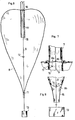
- the auxiliary carrier balloon 1 shown diagrammatically in FIG. 1 has a substantially cylindrical shape of small diameter relative to its height; it includes a non-extensible axial link 2, for example a braided polyester cable, which connects its upper pole 3 and its lower pole 4.
- a non-extensible axial link 2 for example a braided polyester cable, which connects its upper pole 3 and its lower pole 4.
- This carrier balloon is produced by means of spindles such as 5, of constant width over a large part of their height and which narrow in the vicinity of their ends.
- spindles can be made of a reinforced polyethylene film with a thickness of the order of 50 microns.
- These spindles are assembled edge to edge by means of longitudinal reinforcing strips such as 6, capable of supporting part of the longitudinal forces exerted on the envelope.
- the assembly of two spindles is achieved by means of two reinforcing strips arranged on either side of the film.
- the spindles are interrupted to form an opening la; the reinforcing bands extend at the level of this as shown in FIG. 2 and are fixed together on the axial link so as to transmit to it a part of the forces.
- a transfer sleeve 7 is fixed under the carrier balloon opposite the opening 1a thereof.
- the reinforcing bands are fixed on the axial link for the transmission of forces.
- a valve can be conventionally mounted at this upper pole to allow vertical control of the carrier balloon.
- Such a balloon of modest volume is easy to manufacture and inexpensive, in particular because of the shape of its spindles with straight edges.
- the combination of a high-resistance film, longitudinal reinforcement strips and the axial link makes it possible to produce a carrier balloon capable of withstanding significant stresses and to pass without damage through the lower layers of the atmosphere and the tropopause, causing a heavy load.
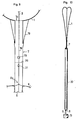
- Figures 6, 7 and 8 show schematically a space balloon, called to be launched by means of the carrier balloon described above.
- This space balloon consists of an envelope 8 made of a polyester film, of very small thickness less than 10 microns; this balloon has an axial link 9 of the same type as that of the carrier balloon.
- the upper pole 10 of the space balloon is linked to this axial link, while the lower pole 11 can slide along this link until it reaches a final position where it is blocked at the level of a member 12 secured on the axial link. .
- This blocking can be achieved by snap-fastening of a member secured to the pole 11 with the conjugate member 12 fixed on the link.
- the axial link 9 extends below the space balloon and a load 13 is attached to the end of it.
- the envelope 8 can be made as for the carrier balloon by means of a plurality of longitudinal spindles assembled edge to edge by means of longitudinal reinforcing strips. At the upper pole 9 of the balloon, the spindles are interrupted to form an opening 8a and the reinforcing bands (which can be seen at 14 in FIG. 7) extend to the axial link 9 to be fixed on it this.
- an opening 8b is provided at the lower pole 11 ( Figure 8).
- a conventional evacuation sleeve 15 is fixed under the balloon opposite the opening 8b in order to allow evacuation of gas from the ceiling.
- a flexible and deformable sleeve 16 made of polyethylene about 20 microns thick is fixed inside the space balloon around the opening 8a in extension of the transfer sleeve 7.
- This flexible sleeve 16 extends over part of the length of the axial cable 9 so that the transferred gas ensures expansion of the balloon almost over its entire height.
- This flexible sleeve 16 is called upon to act as a closing valve when the hydrostatic pressure inside the space balloon reaches a determined value; it is surrounded by a sheath 17, resistant and permeable to gas. This sheath prevents the centrifugal deformation of the flexible sleeve 16 from occurring during the transfer of gas, while allowing this sleeve to deform in the centripetal direction.
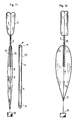
- FIG 9 there is shown schematically the transfer sleeve 7 which connects the carrier balloon 1 and the space balloon 8 and allows to connect the openings 1a and 8a of these balloons; this sleeve is made of a reinforced polyethylene type material, of the order of 50 microns thick; so as to have a high resistance; it contains a link 18 extending and connecting the axial links 2 and 9 of the carrier balloon and space balloon.
- the transfer sleeve 7 is provided with an anti-torsion device shown diagrammatically in 19 which may consist of several elastic tie rods hung under the carrier balloon and on the sleeve so as to exert an elastic traction upwards on the latter.
- an anti-torsion device shown diagrammatically in 19 which may consist of several elastic tie rods hung under the carrier balloon and on the sleeve so as to exert an elastic traction upwards on the latter.
- the sleeve 7 is provided with a conventional type member to cut it when ordered.
- This member can be constituted by a loop of electric wire 20, inserted into the material of the sleeve and connected to an electric source to ensure its heating upon command and cause the rupture of the sleeve.
- the link 18 is itself provided with a member 21 making it possible to cause the order to break.
- This organ which is also conventional in itself, can be constituted by an explosive charge or by a mechanical organ comprising two parts hooked to one another and adapted to separate on command.
- the link 18 is further equipped with a member 23 for measuring the tension exerted thereon; this member is arranged to control the member 20 and the member 21 when this voltage drops, in flight, to a predetermined value, in order to generate the separation of the space balloon 8 and the carrier balloon 1.
- the space balloon 8 is housed in the deflated state in a sheath 22, which protects it over its entire height and eliminates the risks of deterioration of its envelope during transport and launch; this sheath is put in place immediately after the manufacture of the balloon, so as to avoid it being manipulated, due to the great fragility of the thin film which forms it.
- the load 13 is attached to the end of the axial cable 9 and the assembly of balloon carrier 1, transfer handle 7 and space balloon 22 in its sheath is extended on the ground on the launch pad.
- the carrier balloon is partially inflated with helium or hydrogen, conventionally by an inflation sleeve not shown; little by little, the carrier balloon takes off and gradually lifts the space balloon.
- a measurement of the Archimedes' thrust can be made at the level of the load 13 and when this thrust reaches a given value corresponding to a quantity of gas in the carrier balloon adapted to the mission, the load 13 is released and the assembly s pupil in the atmosphere.
- this carrier balloon can be inflated on the ground to reach a volume of the order of 1220 m 3 , which determines at the time of release a resultant force directed upwards of the order of 1100 kgf.
- the load 13 is directly supported by the carrier balloon via the cable 9 and the cable 18, the envelope of the space balloon being subjected to no load other than its own weight.
- the elongated shape of the assembly and the modest dimensions of the carrier balloon make launching operations easy to execute.
- the carrier balloon undergoes an expansion which brings it to its state of fullness.
- this state is reached at an altitude of around 15 km, after crossing low atmospheric layers.
- the space balloon receives gas through the transfer sleeve and continues its expansion. Its lower pole 11 gradually slides upwards along the axial cable 9, as illustrated in FIG. 12.
- this pole When this pole reaches the level of the member 12 secured to the cable 9, it locks by snapping onto it and the expansion of the balloon continues with a non-extendable connection between its lower pole and its upper pole.
- this snap-fitting can occur at an altitude of around 40 km.
- the space balloon participates gradually in the drive of the load and the tension on the cable 18 connecting the two balloons decreases; when this voltage reaches a predetermined value, calculated as a function of the desired separation altitude, the transfer sleeve 7 and the cable 18 are cut.
- This separation can in particular be carried out after crossing the tropopause at an altitude of approximately 26.5 km.
- the carrier balloon which is then released from the load escapes upwards at a higher rate of climb than that of the space balloon.
- the hydrodynamic pressure exerted on the flexible sleeve 16 causes the latter to close as shown in FIG. 14 and the natural expansion of the balloon continues until it reaches its state of fullness.
- FIG. 15 shows the profile of a cardiocylindrical balloon in the state of fullness, the volume of which can be of the order of 2,350,000 m 3 at an altitude of 56 km. , for a transported load of 100 kg.
- the aforementioned launching and inflation process makes it possible to make very gradual application of the voltages on the space balloon and considerably reduces local overvoltages and the risks of tearing or dislocation thereof, despite the very low surface mass of its material.
Landscapes
- Engineering & Computer Science (AREA)
- Mechanical Engineering (AREA)
- Aviation & Aerospace Engineering (AREA)
- Toys (AREA)
Priority Applications (1)
| Application Number | Priority Date | Filing Date | Title |
|---|---|---|---|
| AT80201053T ATE3266T1 (de) | 1980-01-04 | 1980-11-06 | Verfahren und vorrichtung zum starten und aufblasen eines raumfahrballons. |
Applications Claiming Priority (2)
| Application Number | Priority Date | Filing Date | Title |
|---|---|---|---|
| FR8000344A FR2473186A1 (fr) | 1980-01-04 | 1980-01-04 | Procede et moyens pour le lancement et le gonflage d'un ballon spatial |
| FR8000344 | 1980-01-04 |
Publications (2)
| Publication Number | Publication Date |
|---|---|
| EP0033020A1 EP0033020A1 (fr) | 1981-08-05 |
| EP0033020B1 true EP0033020B1 (fr) | 1983-05-11 |
Family
ID=9237337
Family Applications (1)
| Application Number | Title | Priority Date | Filing Date |
|---|---|---|---|
| EP80201053A Expired EP0033020B1 (fr) | 1980-01-04 | 1980-11-06 | Procédé et moyens pour le lancement et le gonflage d'un ballon spatial |
Country Status (5)
| Country | Link |
|---|---|
| US (1) | US4387868A (enExample) |
| EP (1) | EP0033020B1 (enExample) |
| AT (1) | ATE3266T1 (enExample) |
| DE (1) | DE3063177D1 (enExample) |
| FR (1) | FR2473186A1 (enExample) |
Families Citing this family (10)
| Publication number | Priority date | Publication date | Assignee | Title |
|---|---|---|---|---|
| FR2580343B1 (fr) * | 1985-04-12 | 1987-05-29 | Centre Nat Etd Spatiales | Procede et dispositif d'accrochage d'une enveloppe sur une piece de fixation |
| FR2612485B1 (fr) * | 1987-03-20 | 1992-02-14 | Bernard Alain | Ballon dirigeable a reserve d'helium embarquee |
| US5104059A (en) * | 1990-06-11 | 1992-04-14 | Winzen International, Inc. | Long endurance high altitude balloon |
| US5645248A (en) * | 1994-08-15 | 1997-07-08 | Campbell; J. Scott | Lighter than air sphere or spheroid having an aperture and pathway |
| US6234425B1 (en) | 1999-05-11 | 2001-05-22 | Winzen Engineering Incorporated | Release fitting for balloons |
| US20070102570A1 (en) * | 2003-02-24 | 2007-05-10 | Luffman Charles R | Aircraft |
| KR101805134B1 (ko) * | 2010-02-11 | 2017-12-06 | 호워드 엠. 친 | 로켓 발사 시스템 및 지지 장치 |
| US10059420B1 (en) * | 2015-12-07 | 2018-08-28 | X Development Llc | Payload separation for balloon flight termination |
| CN108644606B (zh) * | 2018-07-19 | 2023-06-23 | 国家海洋局第一海洋研究所 | 一种船载探空气球自动充气释放装置及使用方法 |
| CN116494560B (zh) * | 2023-03-03 | 2026-01-09 | 南京航空航天大学 | 一种用于复合材料太空在轨编织的多臂成形设备 |
Citations (4)
| Publication number | Priority date | Publication date | Assignee | Title |
|---|---|---|---|---|
| FR1150008A (fr) * | 1956-04-23 | 1958-01-06 | Delacoste & Cie | Dispositif de liaison de ballons de radiosondage |
| US3484058A (en) * | 1967-06-23 | 1969-12-16 | Arthur D Struble Jr | Balloon |
| FR2132569A1 (en) * | 1971-04-09 | 1972-11-24 | Nal Etu Spatiales Centre | Two-chamber stratospheric balloons - made of full length longitudinal panels of polyethylene with lightweight seams and collar |
| FR2136919A1 (enExample) * | 1971-05-07 | 1972-12-29 | Nal Etu Spatiales Centre |
Family Cites Families (6)
| Publication number | Priority date | Publication date | Assignee | Title |
|---|---|---|---|---|
| US1031148A (en) * | 1908-04-14 | 1912-07-02 | Attilio Ranza | Automatically-deformable balloon. |
| US3063656A (en) * | 1954-11-30 | 1962-11-13 | Leland S Bohl | Plastic cylinder balloon |
| US2783002A (en) * | 1954-11-30 | 1957-02-26 | Edward P Ney | Automatic balloon appendix |
| US2919083A (en) * | 1956-03-12 | 1959-12-29 | Winzen Res Inc | Balloon structure and method of launching the same |
| US3311328A (en) * | 1965-04-19 | 1967-03-28 | Schjeldahl Co G T | Tailored woven gores for heavy load balloon |
| FR1535761A (fr) * | 1967-07-03 | 1968-08-09 | Aérostat |
-
1980
- 1980-01-04 FR FR8000344A patent/FR2473186A1/fr active Granted
- 1980-11-06 AT AT80201053T patent/ATE3266T1/de not_active IP Right Cessation
- 1980-11-06 EP EP80201053A patent/EP0033020B1/fr not_active Expired
- 1980-11-06 DE DE8080201053T patent/DE3063177D1/de not_active Expired
- 1980-12-22 US US06/218,728 patent/US4387868A/en not_active Expired - Lifetime
Patent Citations (4)
| Publication number | Priority date | Publication date | Assignee | Title |
|---|---|---|---|---|
| FR1150008A (fr) * | 1956-04-23 | 1958-01-06 | Delacoste & Cie | Dispositif de liaison de ballons de radiosondage |
| US3484058A (en) * | 1967-06-23 | 1969-12-16 | Arthur D Struble Jr | Balloon |
| FR2132569A1 (en) * | 1971-04-09 | 1972-11-24 | Nal Etu Spatiales Centre | Two-chamber stratospheric balloons - made of full length longitudinal panels of polyethylene with lightweight seams and collar |
| FR2136919A1 (enExample) * | 1971-05-07 | 1972-12-29 | Nal Etu Spatiales Centre |
Also Published As
| Publication number | Publication date |
|---|---|
| DE3063177D1 (en) | 1983-06-16 |
| EP0033020A1 (fr) | 1981-08-05 |
| FR2473186B1 (enExample) | 1983-11-10 |
| ATE3266T1 (de) | 1983-05-15 |
| FR2473186A1 (fr) | 1981-07-10 |
| US4387868A (en) | 1983-06-14 |
Similar Documents
| Publication | Publication Date | Title |
|---|---|---|
| EP0033020B1 (fr) | Procédé et moyens pour le lancement et le gonflage d'un ballon spatial | |
| EP0184262A1 (fr) | Ballon aérostatique pilotable | |
| EP0031981B1 (fr) | Procédé de réalisation d'une enveloppe de ballon, en particulier pour ballons spatiaux, enveloppe réalisée, et utilisation de celle-ci dans le domaine aérospatial | |
| EP0895504B1 (fr) | Ballon stratospherique a duree de vol elevee | |
| EP2671805B1 (fr) | Procédé et dispositif de capture et de couplage en vue de la désorbitation ou réorbitation d'un objet dans l'espace | |
| EP2392508B1 (fr) | Procédé et dispositif d'ouverture d'une paroi gonflée | |
| EP0069403B1 (fr) | Procédé pour stabiliser en altitude un ballon, et ballons atmosphériques adaptés pour la mise en oeuvre de ce procédé | |
| EP0401891B1 (fr) | Aerostat destiné à évoluer de facon autonome et réversible entre le sol d'une planète à atmosphère et une altitude plafond prédéterminée | |
| EP0241970B1 (fr) | Procédé et dispositif pour developper une enveloppe autour d'un objet, notamment un satellite | |
| ES2402932T3 (es) | Sistema de repostaje en vuelo y procedimiento para evitar oscilaciones en los componentes del sistema | |
| EP0200244A2 (fr) | Dispositif pour l'accouplement d'une enveloppe avec un élément externe à l'enveloppe | |
| EP3328737B1 (fr) | Dispositif et procédé d'aérofreinage et de passivation de satellite | |
| CA1324998C (fr) | Aerostat destine a evoluer de facon autonome et reversible entre le sol d'une planete a atmosphere et une altitude plafond predeterminee | |
| FR3006987A1 (fr) | Dirigeable a portance variable et procede de pilotage d'un tel dispositif a portance variable | |
| EP3127801B1 (fr) | Parachute de palier | |
| WO1995006585A1 (fr) | Dispositif de protection destine a etre solidarise a une charge sous parachute en vue de proteger cette derniere lors de son atterrissage | |
| EP2855260B1 (fr) | Ballon dirigeable | |
| FR2612485A1 (fr) | Ballon dirigeable a reserve d'helium embarquee | |
| EP3892532B1 (fr) | Système d'ascension stratosphérique à ballonnet partiel | |
| FR2981330A1 (fr) | Aeronef comprenant un aerostat apte a etre fonctionnalise | |
| FR2841533A1 (fr) | Dispositif de protection contre les chocs, notamment d'un vehicule de transport | |
| FR2740755A1 (fr) | Aerostat dirigeable a armature gonflable et a pilotage par balancier | |
| FR3080095A1 (fr) | Systeme pour le lancement d'une aile de parapente depuis la stratosphere | |
| FR2701108A1 (fr) | Dispositif ralentisseur de chute pour une fibre optique ou un organe de liaison analogue reliant un engin à son pas de tir. | |
| WO2005113338A1 (fr) | Procede et dispositif de stabilisation aerodynamique d'un vehicule spatial lors de son retour sur terre |
Legal Events
| Date | Code | Title | Description |
|---|---|---|---|
| PUAI | Public reference made under article 153(3) epc to a published international application that has entered the european phase |
Free format text: ORIGINAL CODE: 0009012 |
|
| AK | Designated contracting states |
Designated state(s): AT BE CH DE GB IT LU NL SE |
|
| 17P | Request for examination filed |
Effective date: 19810918 |
|
| ITF | It: translation for a ep patent filed | ||
| GRAA | (expected) grant |
Free format text: ORIGINAL CODE: 0009210 |
|
| AK | Designated contracting states |
Designated state(s): AT BE CH DE GB IT LI LU NL SE |
|
| PG25 | Lapsed in a contracting state [announced via postgrant information from national office to epo] |
Ref country code: SE Free format text: THE PATENT HAS BEEN ANNULLED BY A DECISION OF A NATIONAL AUTHORITY Effective date: 19830511 |
|
| REF | Corresponds to: |
Ref document number: 3266 Country of ref document: AT Date of ref document: 19830515 Kind code of ref document: T |
|
| PG25 | Lapsed in a contracting state [announced via postgrant information from national office to epo] |
Ref country code: AT Effective date: 19830601 |
|
| REF | Corresponds to: |
Ref document number: 3063177 Country of ref document: DE Date of ref document: 19830616 |
|
| PLBE | No opposition filed within time limit |
Free format text: ORIGINAL CODE: 0009261 |
|
| STAA | Information on the status of an ep patent application or granted ep patent |
Free format text: STATUS: NO OPPOSITION FILED WITHIN TIME LIMIT |
|
| 26N | No opposition filed | ||
| EPTA | Lu: last paid annual fee | ||
| PGFP | Annual fee paid to national office [announced via postgrant information from national office to epo] |
Ref country code: BE Payment date: 19951031 Year of fee payment: 16 |
|
| PGFP | Annual fee paid to national office [announced via postgrant information from national office to epo] |
Ref country code: LU Payment date: 19951101 Year of fee payment: 16 Ref country code: GB Payment date: 19951101 Year of fee payment: 16 |
|
| PGFP | Annual fee paid to national office [announced via postgrant information from national office to epo] |
Ref country code: CH Payment date: 19951117 Year of fee payment: 16 |
|
| PGFP | Annual fee paid to national office [announced via postgrant information from national office to epo] |
Ref country code: NL Payment date: 19951122 Year of fee payment: 16 |
|
| PGFP | Annual fee paid to national office [announced via postgrant information from national office to epo] |
Ref country code: DE Payment date: 19960126 Year of fee payment: 16 |
|
| PG25 | Lapsed in a contracting state [announced via postgrant information from national office to epo] |
Ref country code: LU Free format text: LAPSE BECAUSE OF NON-PAYMENT OF DUE FEES Effective date: 19961106 Ref country code: GB Effective date: 19961106 |
|
| PG25 | Lapsed in a contracting state [announced via postgrant information from national office to epo] |
Ref country code: LI Effective date: 19961130 Ref country code: CH Effective date: 19961130 Ref country code: BE Effective date: 19961130 |
|
| BERE | Be: lapsed |
Owner name: CENTRE NATIONAL D'ETUDES SPATIALES Effective date: 19961130 |
|
| PG25 | Lapsed in a contracting state [announced via postgrant information from national office to epo] |
Ref country code: NL Effective date: 19970601 |
|
| GBPC | Gb: european patent ceased through non-payment of renewal fee |
Effective date: 19961106 |
|
| REG | Reference to a national code |
Ref country code: CH Ref legal event code: PL |
|
| NLV4 | Nl: lapsed or anulled due to non-payment of the annual fee |
Effective date: 19970601 |
|
| PG25 | Lapsed in a contracting state [announced via postgrant information from national office to epo] |
Ref country code: DE Effective date: 19970801 |