EP0031750B1 - Goniomètre acoustique - Google Patents
Goniomètre acoustique Download PDFInfo
- Publication number
- EP0031750B1 EP0031750B1 EP80401780A EP80401780A EP0031750B1 EP 0031750 B1 EP0031750 B1 EP 0031750B1 EP 80401780 A EP80401780 A EP 80401780A EP 80401780 A EP80401780 A EP 80401780A EP 0031750 B1 EP0031750 B1 EP 0031750B1
- Authority
- EP
- European Patent Office
- Prior art keywords
- signals
- phasemeters
- phase shifts
- probes
- values
- Prior art date
- Legal status (The legal status is an assumption and is not a legal conclusion. Google has not performed a legal analysis and makes no representation as to the accuracy of the status listed.)
- Expired
Links
- 230000010363 phase shift Effects 0.000 claims description 60
- 238000001514 detection method Methods 0.000 claims description 2
- 239000000523 sample Substances 0.000 claims 12
- 230000005540 biological transmission Effects 0.000 claims 2
- 230000002950 deficient Effects 0.000 claims 1
- 238000005259 measurement Methods 0.000 description 9
- 238000010586 diagram Methods 0.000 description 6
- 230000035945 sensitivity Effects 0.000 description 2
- PCTMTFRHKVHKIS-BMFZQQSSSA-N (1s,3r,4e,6e,8e,10e,12e,14e,16e,18s,19r,20r,21s,25r,27r,30r,31r,33s,35r,37s,38r)-3-[(2r,3s,4s,5s,6r)-4-amino-3,5-dihydroxy-6-methyloxan-2-yl]oxy-19,25,27,30,31,33,35,37-octahydroxy-18,20,21-trimethyl-23-oxo-22,39-dioxabicyclo[33.3.1]nonatriaconta-4,6,8,10 Chemical compound C1C=C2C[C@@H](OS(O)(=O)=O)CC[C@]2(C)[C@@H]2[C@@H]1[C@@H]1CC[C@H]([C@H](C)CCCC(C)C)[C@@]1(C)CC2.O[C@H]1[C@@H](N)[C@H](O)[C@@H](C)O[C@H]1O[C@H]1/C=C/C=C/C=C/C=C/C=C/C=C/C=C/[C@H](C)[C@@H](O)[C@@H](C)[C@H](C)OC(=O)C[C@H](O)C[C@H](O)CC[C@@H](O)[C@H](O)C[C@H](O)C[C@](O)(C[C@H](O)[C@H]2C(O)=O)O[C@H]2C1 PCTMTFRHKVHKIS-BMFZQQSSSA-N 0.000 description 1
- 230000006870 function Effects 0.000 description 1
- 230000010354 integration Effects 0.000 description 1
- 238000012544 monitoring process Methods 0.000 description 1
- 230000003595 spectral effect Effects 0.000 description 1
- 238000001228 spectrum Methods 0.000 description 1
Images


Classifications
-
- G—PHYSICS
- G01—MEASURING; TESTING
- G01S—RADIO DIRECTION-FINDING; RADIO NAVIGATION; DETERMINING DISTANCE OR VELOCITY BY USE OF RADIO WAVES; LOCATING OR PRESENCE-DETECTING BY USE OF THE REFLECTION OR RERADIATION OF RADIO WAVES; ANALOGOUS ARRANGEMENTS USING OTHER WAVES
- G01S3/00—Direction-finders for determining the direction from which infrasonic, sonic, ultrasonic, or electromagnetic waves, or particle emission, not having a directional significance, are being received
- G01S3/80—Direction-finders for determining the direction from which infrasonic, sonic, ultrasonic, or electromagnetic waves, or particle emission, not having a directional significance, are being received using ultrasonic, sonic or infrasonic waves
- G01S3/802—Systems for determining direction or deviation from predetermined direction
- G01S3/808—Systems for determining direction or deviation from predetermined direction using transducers spaced apart and measuring phase or time difference between signals therefrom, i.e. path-difference systems
- G01S3/8083—Systems for determining direction or deviation from predetermined direction using transducers spaced apart and measuring phase or time difference between signals therefrom, i.e. path-difference systems determining direction of source
Definitions
- the present invention relates to acoustic direction finding devices using phase shift measurements between signals received by sensors of an acoustic antenna, the signals coming from sound sources to be located in the direction.
- Each source emits a substantially sinusoidal signal at a certain frequency and the direction finding device must make it possible to locate sources at frequencies included in a wide frequency band.
- the phase shifts in absolute values must be less than a value ⁇ max less than 180 ° and which depends on the noise level.
- ⁇ max less than 180 ° and which depends on the noise level.
- the present invention has the advantage of significantly increasing the bandwidth of a base compared to the prior art, thereby increasing the spectral range of surveillance.
- US-A-3 935 575 describes a device for determining the direction of a source, in particular by three sensors arranged at the vertices of an isosceles right triangle.
- phase shifts used to calculate the angle of this direction are those between the signals received by the sensors located on the same side of the right angle of the triangle.
- This device has a larger bandwidth, but a lower sensitivity than the device with four sensors, with diagonal phase shift measurements.
- the device according to the invention has the advantage over these goniometers, according to the prior art, of having both a large bandwidth and a good sensitivity.
- the acoustic goniometer for determining the angle direction 0 of sound sources emitting substantially sinusoidal signals is in accordance with the current claim 1.
- FIG. 1 The operating principle of a goniometer, according to the prior art, is shown in Figure 1.
- a base is formed by the four sensors A, B, C and D placed at the corners of a square.
- An incident acoustic wave with a direction of propagation ⁇ , a unit vector û and a frequency f is considered.
- phase shift ⁇ PQ between the signals picked up at P and at Q is given by: where C is the speed of the waves.
- phase shifts are measured from the two signals from the two sensors and the angle value supplied is necessarily between -180 ° and + 180 °.
- phase shifts in absolute values must therefore be less than 180 ° to obtain an unambiguous measurement of direction 0; in fact, in the presence of noise, in order not to exceed 180 °, these phase shifts in absolute values must be less than a value ⁇ max , which depends on the signal to noise ratio.
- ⁇ max the maximum frequency f max admissible on such a goniometer is given according to relations (2) by:
- Such a goniometer is also limited to low frequencies by a minimum frequency f min .
- the value of f min depends on the precision to be obtained for the angle ⁇ of the direction ⁇ , for the whole horizon and on the signal to noise ratio which limits the precision of the measurement of the phase shift. We generally find that f max / f min is of the order of 3.
- a goniometer according to the prior art is shown schematically in Figure 2.
- An antenna comprises two bases each composed of four sensors arranged at the corners of a square.
- the first base includes the sensors, T 1 , T 2 , T 3 and T 4 , the length of the diagonal of the square being d 1 .
- the second base includes the sensors T 5 , T 6 , T 7 and T 8 and the length of the diagonal of the square is d 2 .
- the first base works for frequencies between f min (1) and f max (1) and the second base between f min (2) and f max (2) .
- f max (2) f min (1) and in this case we have:
- Each base is associated with phasemeters operating in the frequency band of the corresponding base.
- the phase shifts between the signals received by the sensors T 1 and T 3 are measured by the phasemeter P 13 and those of the signals received by the sensors T 2 and T 4 by the phasemeter P24.
- the signals of these phase shifts are obtained on the connections 13 and 24.
- the connections and the phase shifters have been numbered by the numbers corresponding to those of the sensors.
- a divider circuit D i receives at its inputs the phase shift signals 13 and 24 thus providing the value tg ⁇ 1 , ⁇ 1 being the angle of the direction of an incident wave situated in the frequency band of the first base.
- ⁇ 1 being the angle of the direction of an incident wave situated in the frequency band of the first base.
- a circuit 1010 providing the angle ⁇ 1 from the value tg ⁇ 1 .
- the circuit 1010 also receives the values of the phase shifts 13 and 24 to resolve the ambiguities on ⁇ 1 , from the respective signs of sin ⁇ 1 and cos ⁇ 1 .
- phase shifters P 57 and P 68 supply phase shift signals, which are applied to another division circuit D 2 providing the value tg ⁇ 2 , ⁇ 2 being the angle of the direction of an incident wave. which is located in the bandwidth of the second base.
- a circuit 1020 provides this value of ⁇ 2 .
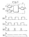
- Figure 3a gives an example of an aperiodic phasemeter P ,.
- the sine signals to be compared 1.i and 2.i are applied respectively to clipping circuits 7.i and 8.i, of outputs 3.i and 4.i.
- These clipped signals are applied to a flip-flop F i and the pulses produced in 5.i are applied to an integrator circuit I i which provides at its output a signal ⁇ i proportional to the phase difference of the signals 1.i and 2.i .
- phase ⁇ i is further determined by logic circuits from signals 3.i and 4.i for example (not shown).
- the goniometer according to the invention uses for the determination of the direction of the sound waves, bases also comprising 4 sensors arranged in a square but using the phase shifts of adjacent sensors of the square.
- This device makes it possible to widen the frequency band of a base compared to the prior art.
- Figure 4 gives an exemplary embodiment according to the invention.
- a first base comprises the sensors T 20 , T 21 , T 22 and T 23 , the length of the diagonal being d 3 .
- a second base comprises the sensors T 24 , T 25 , T 26 and T 27, the length of the diagonal being equal to d 4 .
- the phasemeters bear the numbers corresponding to the signals and the transducers.
- the phasemeters P 2123 and P 2022 measure the phase shifts between the signals received by the sensors opposite by the diagonal of the first base.
- the phasemeters P 2021 and P 2320 measure the phase shifts between the signals received by the adjacent sensors on the square, respectively T 20 , T 21 and T 23 , T 20 .
- phase shifts obtained between diagonal sensors are used, as long as these phase shifts can be measured, i.e. as long as they remain below at the value ⁇ max .
- the phase shifts in absolute value between the sensors on two adjacent sides are equal to ⁇ max / 2. Consequently the phase shifts ⁇ AC and ⁇ BD will not exceed ⁇ max , whatever the direction 8 and the frequency f of the incident wave. when the phase shifts which correspond to two adjacent sides do not exceed the value ⁇ max / 2.
- This switching circuit 8.4 receives the signals 2021, 2123, 2022 and 2320. If the two phase shifts 2021 and 2320 are less than V, the phase shifts 2123 and 2022 are transmitted to the calculation circuit of 10.4 which supplies the value ⁇ 3 of ⁇ following the relation (2 '); on the other hand if one of the two phase shifts 2021 and 2320 is greater than V, the signals in 2021 and 2320 are transmitted to the calculation circuit 10.4 which supplies the value ⁇ 3 of ⁇ according to the relation (5 '). The circuit 10.4 also receives the switching signal in 9.4.
- the second base works analogously to the first by the P 2526 , P 2527 , P 2627 and P 2426 phasemeters .
- the comparison circuit C 30 receives the values of the two phase shifts 2526 and 2627 and controls a switching circuit 8.5 to 9.5.
- the circuit 8.5 receives the phase shifts of the diagonal sensors and of the adjacent sensors as for the first base.
- the calculation circuit 10.5 analogous to circuit 10.4 provides the value ⁇ 4 of ⁇ .
- the first base operates between frequencies f min (3) and f max (3) and the second base operates between frequencies f min (4) and f max (4) and we generally take:
- phase shift values calculated for the diagonal from equation (8) may exceed ⁇ max , the absolute values of ⁇ AB and ⁇ BC remaining less than ⁇ max .
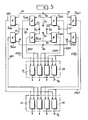
- FIG. 5 An embodiment is shown in FIG. 5 comprising the two bases constituted by the sensors T 61 , T 62 , T 63 , T 64 and T 65 , T 66 , T 67 , T 68 .
- the signal processing for the two bases is identical.
- the P 6162 , P 6263 , P 6364 and P 6461 phasemeters are used and for the second the P 6556 , P 6667 , P 6768 and P 6865 phasemeters .
- the measurements can be made for a base with a pair of phasemeters chosen from the 4 possible couples. According to this embodiment, this redundancy is used in the event of a sensor failure.
- the four pairs of signals which correspond, for each base, to the four possible pairs of phase shifts on two adjacent sides are sent to a set 50 of four processing circuits 51.
- FIG. 6 represents an exemplary embodiment of a circuit 51 for processing two signals such as for example 6162-6263.
- the signals 6162 and 6263 are applied to an addition circuit 100 and to a subtraction circuit 101.
- the phase shift ⁇ 1 between the sensors T 61 and T 63 is obtained at the output of the circuit 100 .
- the phase shift ⁇ 2 between the sensors T 62 and T 64 .
- the circuits 110, 111, 112 and 113 connected to the adder 100 and to the subtractor 101 provide the output respectively the absolute value and the sign of ⁇ 1 and ⁇ 2 .
- the sign is provided in the form of a binary signal equal to 0 or 1.
- are sent on the one hand to a comparator 120 which outputs a binary signal equal to 0 or 1 depending on the result of the comparison, and on the other hand to a circuit 130 which receives the binary signal from the comparator.
- the values of p and q are sent to the circuit 150 via an addressable memory 140 which receives the three binary signals representative of the two signs and of the result of the comparison between
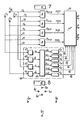
- Figure 7 shows a variant of the invention of signal processing for a base composed of the sensors T 71 , T 72 , T 73 and T 74 .
- the phase shift signals between the adjacent sensors are obtained by the phasemeters P 7172 , P 7273 , P 7374 and P 7471 at 7172, 7273, 7374 and 7471.
- These signals are applied to a microprocessor 70 which provides at its output 80 the angle 0 of the incident wave.
- the microprocessor executes the various operations which were previously carried out by each circuit 51 to obtain an angle ⁇ from two values of phase shifts.
- the microprocessor comprises a programmed memory containing the program for calculating 0 with the calculation steps which correspond to the different functions of circuit 51.
- the signals 71, 72, 73 and 74 coming from the sensors of the base are sent in a set of circuits 90 which supplies the microprocessor with six binary signals Q 1 , Q 2 , Q 3 , Q 4 , Q 5 and Q 6 forming a number. This number is tested to arrive at the choice of the pair of phase shift values corresponding to the three sensors whose signals are relatively the least different in amplitude; in particular, these binary signals make it possible to determine whether a sensor is faulty or unusable owing to its too low amplitude.
- the signals at 71, 72, 73 and 74 of the four sensors are applied to detection and integration circuits 61, 62, 63 and 64 which supply their signals with signals equal to a, b, c, and d.
- a calculation circuit 60 supplies the signals ab, ac, bc, bd and cd equal to the absolute values of log (a / b), log (a / c), log (a / d), log (b / c), log (b / d) and log (c / d).
- the comparators C 1 , C 2 , C 3 , C 4 , C 5 and C 6 provide the binary signals Q 1 , Q 2 , Q 3 , Q 4 , Q 5 and Q 6 . These binary signals are equal to I if the signal applied to the comparators C ,, C 2 , C 3 , C 4 , C 5 and C 6 exceeds a predetermined threshold value.
- the binary signals Q 1 , Q 2 , Q 3 , Q 4 , Q 5 and Q 6 are applied to the microprocessor 70. These signals form an address which controls the choice of the pair of phase shift values, if there is no at least two unusable sensors.
- Another means of detecting a faulty sensor or phasemeter is used, which consists in adding algebraically the phase shifts in 7172, 7273, 7374, and 7471. This sum being zero in the case where no sensor is in failure, it is compared with a predetermined value close to zero. If the sum obtained is less than this value a signal 82 is generated indicating that there is a fault in the sensors or phasemeters.
- the signals 71, 72, 73 and 74 coming from the sensors are sent to the microprocessor which implements a calculation program previously recorded in a programmable memory, this program performing the operations implemented by the circuits of the 'together 90.
- Figure 8 shows a variant of the invention for which the antenna is formed of two bases which have in common a sensor.
- the first base is made up of the sensors T 81 , T 82 , T 83 and T 84 and the second base of the T 85 , T 82 , T 86 and T 87 sensors.
- the sensor T S2 is therefore common to the two bases.
- the operation of the goniometer is similar to that of Figures 4 and 5 except that a sensor is common to the two bases.
Landscapes
- Physics & Mathematics (AREA)
- Engineering & Computer Science (AREA)
- General Physics & Mathematics (AREA)
- Radar, Positioning & Navigation (AREA)
- Remote Sensing (AREA)
- Measurement Of Velocity Or Position Using Acoustic Or Ultrasonic Waves (AREA)
- Measurement Of Mechanical Vibrations Or Ultrasonic Waves (AREA)
Applications Claiming Priority (2)
| Application Number | Priority Date | Filing Date | Title |
|---|---|---|---|
| FR7931487 | 1979-12-21 | ||
| FR7931487A FR2472192A1 (fr) | 1979-12-21 | 1979-12-21 | Goniometre acoustique |
Publications (2)
| Publication Number | Publication Date |
|---|---|
| EP0031750A1 EP0031750A1 (fr) | 1981-07-08 |
| EP0031750B1 true EP0031750B1 (fr) | 1984-11-14 |
Family
ID=9233095
Family Applications (1)
| Application Number | Title | Priority Date | Filing Date |
|---|---|---|---|
| EP80401780A Expired EP0031750B1 (fr) | 1979-12-21 | 1980-12-12 | Goniomètre acoustique |
Country Status (3)
| Country | Link |
|---|---|
| EP (1) | EP0031750B1 (show.php) |
| DE (1) | DE3069648D1 (show.php) |
| FR (1) | FR2472192A1 (show.php) |
Families Citing this family (2)
| Publication number | Priority date | Publication date | Assignee | Title |
|---|---|---|---|---|
| FR2520511B1 (fr) * | 1982-01-22 | 1986-02-07 | Dapa Systemes | Procede de localisation automatique d'ondes radioelectriques incidentes et dispositif pour sa mise en oeuvre |
| EP0116777B1 (en) * | 1982-12-22 | 1990-03-21 | The Marconi Company Limited | Acoustic direction finding systems |
Citations (4)
| Publication number | Priority date | Publication date | Assignee | Title |
|---|---|---|---|---|
| US3383690A (en) * | 1965-03-03 | 1968-05-14 | Motorola Inc | Bearing measurement system |
| US3392392A (en) * | 1967-06-05 | 1968-07-09 | Motorola Inc | Bearing measurement system using statistical signal processing by analog techniques |
| US3935575A (en) * | 1971-12-03 | 1976-01-27 | Fried. Krupp Gesellschaft Mit Beschrankter Haftung | Circuitry for determining direction of impingement of a received signal |
| US4170774A (en) * | 1972-01-24 | 1979-10-09 | United Technologies Corporation | Amplitude selected phase interferometer angle measuring radar |
Family Cites Families (1)
| Publication number | Priority date | Publication date | Assignee | Title |
|---|---|---|---|---|
| US3859621A (en) * | 1973-11-02 | 1975-01-07 | Honeywell Inc | Acoustic direction determination system |
-
1979
- 1979-12-21 FR FR7931487A patent/FR2472192A1/fr active Granted
-
1980
- 1980-12-12 EP EP80401780A patent/EP0031750B1/fr not_active Expired
- 1980-12-12 DE DE8080401780T patent/DE3069648D1/de not_active Expired
Patent Citations (4)
| Publication number | Priority date | Publication date | Assignee | Title |
|---|---|---|---|---|
| US3383690A (en) * | 1965-03-03 | 1968-05-14 | Motorola Inc | Bearing measurement system |
| US3392392A (en) * | 1967-06-05 | 1968-07-09 | Motorola Inc | Bearing measurement system using statistical signal processing by analog techniques |
| US3935575A (en) * | 1971-12-03 | 1976-01-27 | Fried. Krupp Gesellschaft Mit Beschrankter Haftung | Circuitry for determining direction of impingement of a received signal |
| US4170774A (en) * | 1972-01-24 | 1979-10-09 | United Technologies Corporation | Amplitude selected phase interferometer angle measuring radar |
Also Published As
| Publication number | Publication date |
|---|---|
| DE3069648D1 (en) | 1984-12-20 |
| FR2472192A1 (fr) | 1981-06-26 |
| EP0031750A1 (fr) | 1981-07-08 |
| FR2472192B1 (show.php) | 1983-09-02 |
Similar Documents
| Publication | Publication Date | Title |
|---|---|---|
| EP0125838B1 (en) | Direction finding | |
| EP0064908B1 (fr) | Procédé et dispositif de mesure de température d'un corps à l'aide de micro-ondes | |
| EP2198323B1 (en) | Time delay estimation | |
| US4975710A (en) | Methods and apparatus for direction of arrival measurement and radio navigation aids | |
| FR2648570A1 (fr) | Dispositif et procede pour mesurer l'azimut et le site d'un objet | |
| RU2365931C2 (ru) | Фазовый способ пеленгации и фазовый пеленгатор для его осуществления | |
| EP0017532A1 (fr) | Dispositif de traitement de signaux d'écartométrie angulaire d'un radar monopulse et radar comportant un tel dispositif | |
| EP0031750B1 (fr) | Goniomètre acoustique | |
| KR970010876B1 (ko) | 다중 통로 널링을 갖는 간섭계 데이타 처리 방법 | |
| EP0538096B1 (fr) | Procédé et dispositif de mesure de courtes distances par analyse du retard de propagation d'une onde | |
| EP3417310B1 (fr) | Procédé de localisation de sources d'émission d'impulsions électromagnétiques dans un environnement comprenant des réflecteurs | |
| FR2532417A1 (fr) | Disposition interferometrique pour la mesure de distances opto-electriques | |
| EP0492392B1 (fr) | Dispositif de contrÔle non destructif à courants de Foucault | |
| EP2671089A1 (fr) | Procede de mesure de frequences d'emission au moyen d'un interferometre rotatif | |
| FR2833712A1 (fr) | Procede de localisation passive d'une cible et notamment de localisation air-air | |
| FR3073627A1 (fr) | Interferometre et plate-forme associee | |
| EP0886148B1 (fr) | Procédés et systèmes de localisation radiosatellitaire en temps réel, notamment de type GPS | |
| EP3635428A1 (fr) | Procédé et dispositif d'estimation d'un angle d'arrivée d'un signal radioélectrique incident | |
| RU2165628C1 (ru) | Фазовый пеленгатор | |
| US7705609B2 (en) | Phase frequency distortion measurement system | |
| FR2725526A1 (fr) | Radar monopulse aeroporte du type air-sol | |
| RU2321014C2 (ru) | Способ пеленгования радиосигналов и многоканальный пеленгатор | |
| JP7380382B2 (ja) | 測距計 | |
| EP0807828A1 (fr) | Procédé et dispositif de repérage de la position d'une source dotée d'un émetteur de micro-ondes | |
| FR2514901A1 (fr) | Procede et dispositif pour comparer l'amplitude et la phase instantanees de deux signaux electriques sinusoidaux de meme frequence et application a la formation d'image par radar |
Legal Events
| Date | Code | Title | Description |
|---|---|---|---|
| PUAI | Public reference made under article 153(3) epc to a published international application that has entered the european phase |
Free format text: ORIGINAL CODE: 0009012 |
|
| AK | Designated contracting states |
Designated state(s): DE GB IT NL SE |
|
| 17P | Request for examination filed |
Effective date: 19810810 |
|
| ITF | It: translation for a ep patent filed | ||
| GRAA | (expected) grant |
Free format text: ORIGINAL CODE: 0009210 |
|
| AK | Designated contracting states |
Designated state(s): DE GB IT NL SE |
|
| REF | Corresponds to: |
Ref document number: 3069648 Country of ref document: DE Date of ref document: 19841220 |
|
| PGFP | Annual fee paid to national office [announced via postgrant information from national office to epo] |
Ref country code: SE Payment date: 19841231 Year of fee payment: 5 |
|
| PLBE | No opposition filed within time limit |
Free format text: ORIGINAL CODE: 0009261 |
|
| STAA | Information on the status of an ep patent application or granted ep patent |
Free format text: STATUS: NO OPPOSITION FILED WITHIN TIME LIMIT |
|
| 26N | No opposition filed | ||
| PGFP | Annual fee paid to national office [announced via postgrant information from national office to epo] |
Ref country code: NL Payment date: 19871231 Year of fee payment: 8 |
|
| PGFP | Annual fee paid to national office [announced via postgrant information from national office to epo] |
Ref country code: DE Payment date: 19891124 Year of fee payment: 10 |
|
| PGFP | Annual fee paid to national office [announced via postgrant information from national office to epo] |
Ref country code: GB Payment date: 19891130 Year of fee payment: 10 |
|
| PG25 | Lapsed in a contracting state [announced via postgrant information from national office to epo] |
Ref country code: SE Effective date: 19891213 |
|
| ITTA | It: last paid annual fee | ||
| PG25 | Lapsed in a contracting state [announced via postgrant information from national office to epo] |
Ref country code: NL Effective date: 19900701 |
|
| NLV4 | Nl: lapsed or anulled due to non-payment of the annual fee | ||
| PG25 | Lapsed in a contracting state [announced via postgrant information from national office to epo] |
Ref country code: GB Effective date: 19901212 |
|
| GBPC | Gb: european patent ceased through non-payment of renewal fee | ||
| PG25 | Lapsed in a contracting state [announced via postgrant information from national office to epo] |
Ref country code: DE Effective date: 19910903 |
|
| EUG | Se: european patent has lapsed |
Ref document number: 80401780.4 Effective date: 19900709 |