EP0031750B1 - Acoustic goniometer - Google Patents
Acoustic goniometer Download PDFInfo
- Publication number
- EP0031750B1 EP0031750B1 EP80401780A EP80401780A EP0031750B1 EP 0031750 B1 EP0031750 B1 EP 0031750B1 EP 80401780 A EP80401780 A EP 80401780A EP 80401780 A EP80401780 A EP 80401780A EP 0031750 B1 EP0031750 B1 EP 0031750B1
- Authority
- EP
- European Patent Office
- Prior art keywords
- signals
- phasemeters
- phase shifts
- probes
- values
- Prior art date
- Legal status (The legal status is an assumption and is not a legal conclusion. Google has not performed a legal analysis and makes no representation as to the accuracy of the status listed.)
- Expired
Links
Images


Classifications
-
- G—PHYSICS
- G01—MEASURING; TESTING
- G01S—RADIO DIRECTION-FINDING; RADIO NAVIGATION; DETERMINING DISTANCE OR VELOCITY BY USE OF RADIO WAVES; LOCATING OR PRESENCE-DETECTING BY USE OF THE REFLECTION OR RERADIATION OF RADIO WAVES; ANALOGOUS ARRANGEMENTS USING OTHER WAVES
- G01S3/00—Direction-finders for determining the direction from which infrasonic, sonic, ultrasonic, or electromagnetic waves, or particle emission, not having a directional significance, are being received
- G01S3/80—Direction-finders for determining the direction from which infrasonic, sonic, ultrasonic, or electromagnetic waves, or particle emission, not having a directional significance, are being received using ultrasonic, sonic or infrasonic waves
- G01S3/802—Systems for determining direction or deviation from predetermined direction
- G01S3/808—Systems for determining direction or deviation from predetermined direction using transducers spaced apart and measuring phase or time difference between signals therefrom, i.e. path-difference systems
- G01S3/8083—Systems for determining direction or deviation from predetermined direction using transducers spaced apart and measuring phase or time difference between signals therefrom, i.e. path-difference systems determining direction of source
Definitions
- the present invention relates to acoustic direction finding devices using phase shift measurements between signals received by sensors of an acoustic antenna, the signals coming from sound sources to be located in the direction.
- Each source emits a substantially sinusoidal signal at a certain frequency and the direction finding device must make it possible to locate sources at frequencies included in a wide frequency band.
- the phase shifts in absolute values must be less than a value ⁇ max less than 180 ° and which depends on the noise level.
- ⁇ max less than 180 ° and which depends on the noise level.
- the present invention has the advantage of significantly increasing the bandwidth of a base compared to the prior art, thereby increasing the spectral range of surveillance.
- US-A-3 935 575 describes a device for determining the direction of a source, in particular by three sensors arranged at the vertices of an isosceles right triangle.
- phase shifts used to calculate the angle of this direction are those between the signals received by the sensors located on the same side of the right angle of the triangle.
- This device has a larger bandwidth, but a lower sensitivity than the device with four sensors, with diagonal phase shift measurements.
- the device according to the invention has the advantage over these goniometers, according to the prior art, of having both a large bandwidth and a good sensitivity.
- the acoustic goniometer for determining the angle direction 0 of sound sources emitting substantially sinusoidal signals is in accordance with the current claim 1.
- FIG. 1 The operating principle of a goniometer, according to the prior art, is shown in Figure 1.
- a base is formed by the four sensors A, B, C and D placed at the corners of a square.
- An incident acoustic wave with a direction of propagation ⁇ , a unit vector û and a frequency f is considered.
- phase shift ⁇ PQ between the signals picked up at P and at Q is given by: where C is the speed of the waves.
- phase shifts are measured from the two signals from the two sensors and the angle value supplied is necessarily between -180 ° and + 180 °.
- phase shifts in absolute values must therefore be less than 180 ° to obtain an unambiguous measurement of direction 0; in fact, in the presence of noise, in order not to exceed 180 °, these phase shifts in absolute values must be less than a value ⁇ max , which depends on the signal to noise ratio.
- ⁇ max the maximum frequency f max admissible on such a goniometer is given according to relations (2) by:
- Such a goniometer is also limited to low frequencies by a minimum frequency f min .
- the value of f min depends on the precision to be obtained for the angle ⁇ of the direction ⁇ , for the whole horizon and on the signal to noise ratio which limits the precision of the measurement of the phase shift. We generally find that f max / f min is of the order of 3.
- a goniometer according to the prior art is shown schematically in Figure 2.
- An antenna comprises two bases each composed of four sensors arranged at the corners of a square.
- the first base includes the sensors, T 1 , T 2 , T 3 and T 4 , the length of the diagonal of the square being d 1 .
- the second base includes the sensors T 5 , T 6 , T 7 and T 8 and the length of the diagonal of the square is d 2 .
- the first base works for frequencies between f min (1) and f max (1) and the second base between f min (2) and f max (2) .
- f max (2) f min (1) and in this case we have:
- Each base is associated with phasemeters operating in the frequency band of the corresponding base.
- the phase shifts between the signals received by the sensors T 1 and T 3 are measured by the phasemeter P 13 and those of the signals received by the sensors T 2 and T 4 by the phasemeter P24.
- the signals of these phase shifts are obtained on the connections 13 and 24.
- the connections and the phase shifters have been numbered by the numbers corresponding to those of the sensors.
- a divider circuit D i receives at its inputs the phase shift signals 13 and 24 thus providing the value tg ⁇ 1 , ⁇ 1 being the angle of the direction of an incident wave situated in the frequency band of the first base.
- ⁇ 1 being the angle of the direction of an incident wave situated in the frequency band of the first base.
- a circuit 1010 providing the angle ⁇ 1 from the value tg ⁇ 1 .
- the circuit 1010 also receives the values of the phase shifts 13 and 24 to resolve the ambiguities on ⁇ 1 , from the respective signs of sin ⁇ 1 and cos ⁇ 1 .
- phase shifters P 57 and P 68 supply phase shift signals, which are applied to another division circuit D 2 providing the value tg ⁇ 2 , ⁇ 2 being the angle of the direction of an incident wave. which is located in the bandwidth of the second base.
- a circuit 1020 provides this value of ⁇ 2 .
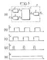
- Figure 3a gives an example of an aperiodic phasemeter P ,.
- the sine signals to be compared 1.i and 2.i are applied respectively to clipping circuits 7.i and 8.i, of outputs 3.i and 4.i.
- These clipped signals are applied to a flip-flop F i and the pulses produced in 5.i are applied to an integrator circuit I i which provides at its output a signal ⁇ i proportional to the phase difference of the signals 1.i and 2.i .
- phase ⁇ i is further determined by logic circuits from signals 3.i and 4.i for example (not shown).
- the goniometer according to the invention uses for the determination of the direction of the sound waves, bases also comprising 4 sensors arranged in a square but using the phase shifts of adjacent sensors of the square.
- This device makes it possible to widen the frequency band of a base compared to the prior art.
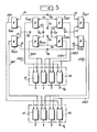
- Figure 4 gives an exemplary embodiment according to the invention.
- a first base comprises the sensors T 20 , T 21 , T 22 and T 23 , the length of the diagonal being d 3 .
- a second base comprises the sensors T 24 , T 25 , T 26 and T 27, the length of the diagonal being equal to d 4 .
- the phasemeters bear the numbers corresponding to the signals and the transducers.
- the phasemeters P 2123 and P 2022 measure the phase shifts between the signals received by the sensors opposite by the diagonal of the first base.
- the phasemeters P 2021 and P 2320 measure the phase shifts between the signals received by the adjacent sensors on the square, respectively T 20 , T 21 and T 23 , T 20 .
- phase shifts obtained between diagonal sensors are used, as long as these phase shifts can be measured, i.e. as long as they remain below at the value ⁇ max .
- the phase shifts in absolute value between the sensors on two adjacent sides are equal to ⁇ max / 2. Consequently the phase shifts ⁇ AC and ⁇ BD will not exceed ⁇ max , whatever the direction 8 and the frequency f of the incident wave. when the phase shifts which correspond to two adjacent sides do not exceed the value ⁇ max / 2.
- This switching circuit 8.4 receives the signals 2021, 2123, 2022 and 2320. If the two phase shifts 2021 and 2320 are less than V, the phase shifts 2123 and 2022 are transmitted to the calculation circuit of 10.4 which supplies the value ⁇ 3 of ⁇ following the relation (2 '); on the other hand if one of the two phase shifts 2021 and 2320 is greater than V, the signals in 2021 and 2320 are transmitted to the calculation circuit 10.4 which supplies the value ⁇ 3 of ⁇ according to the relation (5 '). The circuit 10.4 also receives the switching signal in 9.4.
- the second base works analogously to the first by the P 2526 , P 2527 , P 2627 and P 2426 phasemeters .
- the comparison circuit C 30 receives the values of the two phase shifts 2526 and 2627 and controls a switching circuit 8.5 to 9.5.
- the circuit 8.5 receives the phase shifts of the diagonal sensors and of the adjacent sensors as for the first base.
- the calculation circuit 10.5 analogous to circuit 10.4 provides the value ⁇ 4 of ⁇ .
- the first base operates between frequencies f min (3) and f max (3) and the second base operates between frequencies f min (4) and f max (4) and we generally take:
- phase shift values calculated for the diagonal from equation (8) may exceed ⁇ max , the absolute values of ⁇ AB and ⁇ BC remaining less than ⁇ max .
- FIG. 5 An embodiment is shown in FIG. 5 comprising the two bases constituted by the sensors T 61 , T 62 , T 63 , T 64 and T 65 , T 66 , T 67 , T 68 .
- the signal processing for the two bases is identical.
- the P 6162 , P 6263 , P 6364 and P 6461 phasemeters are used and for the second the P 6556 , P 6667 , P 6768 and P 6865 phasemeters .
- the measurements can be made for a base with a pair of phasemeters chosen from the 4 possible couples. According to this embodiment, this redundancy is used in the event of a sensor failure.
- the four pairs of signals which correspond, for each base, to the four possible pairs of phase shifts on two adjacent sides are sent to a set 50 of four processing circuits 51.
- FIG. 6 represents an exemplary embodiment of a circuit 51 for processing two signals such as for example 6162-6263.
- the signals 6162 and 6263 are applied to an addition circuit 100 and to a subtraction circuit 101.
- the phase shift ⁇ 1 between the sensors T 61 and T 63 is obtained at the output of the circuit 100 .
- the phase shift ⁇ 2 between the sensors T 62 and T 64 .
- the circuits 110, 111, 112 and 113 connected to the adder 100 and to the subtractor 101 provide the output respectively the absolute value and the sign of ⁇ 1 and ⁇ 2 .
- the sign is provided in the form of a binary signal equal to 0 or 1.
- are sent on the one hand to a comparator 120 which outputs a binary signal equal to 0 or 1 depending on the result of the comparison, and on the other hand to a circuit 130 which receives the binary signal from the comparator.
- the values of p and q are sent to the circuit 150 via an addressable memory 140 which receives the three binary signals representative of the two signs and of the result of the comparison between
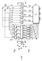
- Figure 7 shows a variant of the invention of signal processing for a base composed of the sensors T 71 , T 72 , T 73 and T 74 .
- the phase shift signals between the adjacent sensors are obtained by the phasemeters P 7172 , P 7273 , P 7374 and P 7471 at 7172, 7273, 7374 and 7471.
- These signals are applied to a microprocessor 70 which provides at its output 80 the angle 0 of the incident wave.
- the microprocessor executes the various operations which were previously carried out by each circuit 51 to obtain an angle ⁇ from two values of phase shifts.
- the microprocessor comprises a programmed memory containing the program for calculating 0 with the calculation steps which correspond to the different functions of circuit 51.
- the signals 71, 72, 73 and 74 coming from the sensors of the base are sent in a set of circuits 90 which supplies the microprocessor with six binary signals Q 1 , Q 2 , Q 3 , Q 4 , Q 5 and Q 6 forming a number. This number is tested to arrive at the choice of the pair of phase shift values corresponding to the three sensors whose signals are relatively the least different in amplitude; in particular, these binary signals make it possible to determine whether a sensor is faulty or unusable owing to its too low amplitude.
- the signals at 71, 72, 73 and 74 of the four sensors are applied to detection and integration circuits 61, 62, 63 and 64 which supply their signals with signals equal to a, b, c, and d.
- a calculation circuit 60 supplies the signals ab, ac, bc, bd and cd equal to the absolute values of log (a / b), log (a / c), log (a / d), log (b / c), log (b / d) and log (c / d).
- the comparators C 1 , C 2 , C 3 , C 4 , C 5 and C 6 provide the binary signals Q 1 , Q 2 , Q 3 , Q 4 , Q 5 and Q 6 . These binary signals are equal to I if the signal applied to the comparators C ,, C 2 , C 3 , C 4 , C 5 and C 6 exceeds a predetermined threshold value.
- the binary signals Q 1 , Q 2 , Q 3 , Q 4 , Q 5 and Q 6 are applied to the microprocessor 70. These signals form an address which controls the choice of the pair of phase shift values, if there is no at least two unusable sensors.
- Another means of detecting a faulty sensor or phasemeter is used, which consists in adding algebraically the phase shifts in 7172, 7273, 7374, and 7471. This sum being zero in the case where no sensor is in failure, it is compared with a predetermined value close to zero. If the sum obtained is less than this value a signal 82 is generated indicating that there is a fault in the sensors or phasemeters.
- the signals 71, 72, 73 and 74 coming from the sensors are sent to the microprocessor which implements a calculation program previously recorded in a programmable memory, this program performing the operations implemented by the circuits of the 'together 90.
- Figure 8 shows a variant of the invention for which the antenna is formed of two bases which have in common a sensor.
- the first base is made up of the sensors T 81 , T 82 , T 83 and T 84 and the second base of the T 85 , T 82 , T 86 and T 87 sensors.
- the sensor T S2 is therefore common to the two bases.
- the operation of the goniometer is similar to that of Figures 4 and 5 except that a sensor is common to the two bases.
Description
La présente invention se rapporte aux dispositifs de goniométrie acoustique utilisant des mesures de déphasage entre des signaux reçus par des capteurs d'une antenne acoustique, les signaux provenant de sources sonores à localiser en direction. Chaque source émet un signal sensiblement sinusoïdal à une certaine fréquence et le dispositif de goniométrie doit permettre de localiser des sources à des fréquences comprises dans une large bande de fréquence.The present invention relates to acoustic direction finding devices using phase shift measurements between signals received by sensors of an acoustic antenna, the signals coming from sound sources to be located in the direction. Each source emits a substantially sinusoidal signal at a certain frequency and the direction finding device must make it possible to locate sources at frequencies included in a wide frequency band.
Il est connu, notamment par le brevet français No. 1.605.544, de disposer des capteurs aux quatre coins d'un carré formant une base de mesure, ou base, pour les mesures de localisation dans une bande de fréquence. Les déphasages entre capteurs situés sur une même diagonale sont mesurés et les signaux de ces déphasages sont appliqués sur les plaques horizontales et verticales d'un oscillographe fournissant la direction de localisation cherchée dans le plan formé par les capteurs.It is known, in particular from French patent No. 1,605,544, to have sensors at the four corners of a square forming a measurement base, or base, for location measurements in a frequency band. The phase shifts between sensors located on the same diagonal are measured and the signals of these phase shifts are applied to the horizontal and vertical plates of an oscillograph providing the location direction sought in the plane formed by the sensors.
Pour pouvoir déterminer la direction des sources sans ambiguîté, il faut que les déphasages en valeurs absolues soient inférieures à une valeur Φmax inférieure à 180° et qui dépend du niveau de bruit. Ainsi pour une base de dimension donnée les fréquences auxquelles il est possible de travailler sont comprises entre deux fréquences fmln et fmax et l'on a généralement fmax/fmin≃3. Si donc on veut localiser des sources pour des spectres plus larges il est nécessaire de multiplier le nombre de bases.In order to be able to determine the direction of the sources without ambiguity, the phase shifts in absolute values must be less than a value Φ max less than 180 ° and which depends on the noise level. Thus for a base of given dimension the frequencies at which it is possible to work are between two frequencies f mln and f max and one generally has f max / f min ≃3. If therefore we want to locate sources for wider spectra it is necessary to multiply the number of bases.
La présente invention a l'avantage d'augmenter notablement la bande passante d'une base par rapport à l'art antérieur augmentant ainsi le domaine spectral de surveillance.The present invention has the advantage of significantly increasing the bandwidth of a base compared to the prior art, thereby increasing the spectral range of surveillance.
Le brevet US-A-3 935 575 décrit un dispositif de détermination de la direction d'une source notamment par trois capteurs disposés aux sommets d'un triangle rectangle isocèle.US-A-3 935 575 describes a device for determining the direction of a source, in particular by three sensors arranged at the vertices of an isosceles right triangle.
Les déphasages utilisés pour le calcul de l'angle de cette direction sont ceux entre les signaux reçus par les capteurs situés sur un même côté de l'angle droit du triangle.The phase shifts used to calculate the angle of this direction are those between the signals received by the sensors located on the same side of the right angle of the triangle.
Ce dispositif a une plus grande bande passante, mais une sensibilité plus faible que le dispositif à quatre capteurs, avec mesures de déphasages aux diagonales.This device has a larger bandwidth, but a lower sensitivity than the device with four sensors, with diagonal phase shift measurements.
Le dispositif suivant l'invention a l'avantage par rapport à ces goniomètres, suivant l'art antérieur, d'avoir à la fois une grande bande passante et une bonne sensibilité.The device according to the invention has the advantage over these goniometers, according to the prior art, of having both a large bandwidth and a good sensitivity.
Selon l'invention, le goniomètre acoustique pour la détermination de la direction d'angle 0 de sources sonores émettant des signaux sensiblement sinusoïdaux, est conforme à l'actuelle revendication 1.According to the invention, the acoustic goniometer for determining the angle direction 0 of sound sources emitting substantially sinusoidal signals, is in accordance with the
D'autres caractéristiques et avantages ressortiront de la description qui va suivre illustrée par les figures qui représentent:
- - la Figure 1, une base de goniomètre;
- - la Figure 2, le schéma d'un goniomètre suivant l'art antérieur;
- -les Figures 3a à 3e le schéma d'un déphaseur apériodique avec les signaux correspondants;
- - la Figure 4, le schéma d'un goniomètre, suivant l'invention;
- - les Figures 5 et 6, les schémas d'un goniomètre, suivant des variantes de l'invention;
- la Figure 7, le schéma d'un goniomètre avec microprocesseur suivant une autre variante de l'invention;
- -la Figure 8, un schéma de disposition des capteurs pour deux bases, suivant l'invention.
- - Figure 1, a goniometer base;
- - Figure 2, the diagram of a goniometer according to the prior art;
- FIGS. 3a to 3e the diagram of an aperiodic phase shifter with the corresponding signals;
- - Figure 4, the diagram of a goniometer, according to the invention;
- - Figures 5 and 6, diagrams of a goniometer, according to variants of the invention;
- Figure 7, the diagram of a goniometer with microprocessor according to another variant of the invention;
- FIG. 8, a diagram of the arrangement of the sensors for two bases, according to the invention.
Le principe de fonctionnement d'un goniomètre, suivant l'art antérieur, est montré par la Figure 1. Une base est formée par les quatre capteurs A, B, C et D placés aux coins d'un carré. On considère une onde acoustique incidente de direction de propagation Δ, de vecteur unitaire û et de fréquence f.The operating principle of a goniometer, according to the prior art, is shown in Figure 1. A base is formed by the four sensors A, B, C and D placed at the corners of a square. An incident acoustic wave with a direction of propagation Δ, a unit vector û and a frequency f is considered.
De façon générale si l'on considère deux capteurs placés en des points P et Q (non représentés sur la figure), le déphasage φPQ entre les signaux captés en P et en Q est donné par:
L'application de la relation (1) à des capteurs opposés sur les diagonales donne: et
L'angle 0 est trouvé à partir des relations (2) par:![]()
![]()
Ces déphasages sont mesurés à partir des deux signaux provenant des deux capteurs et la valeur d'angle fournie est nécessairement comprise entre -180° et +180°.These phase shifts are measured from the two signals from the two sensors and the angle value supplied is necessarily between -180 ° and + 180 °.
Ces déphasages en valeurs absolues doivent donc être inférieurs à 180° pour obtenir une mesure de la direction 0 sans ambiguité; en fait, en présence de bruit, pour ne pas dépasser 180°, il faut que ces déphasages en valeurs absolues soient inférieurs à une valeur Φmax, qui dépend du rapport signal sur bruit. Pour une distance d donnée, la fréquence maximum fmax admissible sur un tel goniomètre est donnée d'après les relations (2) par:
Un tel goniomètre est également limité vers les basses fréquences par une fréquence minimum fmin. La valeur de fmin dépend de la précision à obtenir pour l'angle θ de la direction Δ, pour tout l'horizon et du rapport signal sur bruit qui limite la précision de la mesure du déphasage. On trouve généralement que fmax/fmin est de l'ordre de 3.Such a goniometer is also limited to low frequencies by a minimum frequency f min . The value of f min depends on the precision to be obtained for the angle θ of the direction Δ, for the whole horizon and on the signal to noise ratio which limits the precision of the measurement of the phase shift. We generally find that f max / f min is of the order of 3.
Un goniomètre suivant l'art antérieur, est montré schématiquement par la Figure 2. Une antenne comprend deux bases composées chacune de quatre capteurs disposés aux coins d'un carré. La première base comprend les capteurs, T1, T2, T3 et T4, la longueur de la diagonale du carré étant d1. La seconde base comprend les capteurs T5, T6, T7 et T8 et la longueur de la diagonale du carré est d2.A goniometer according to the prior art, is shown schematically in Figure 2. An antenna comprises two bases each composed of four sensors arranged at the corners of a square. The first base includes the sensors, T 1 , T 2 , T 3 and T 4 , the length of the diagonal of the square being d 1 . The second base includes the sensors T 5 , T 6 , T 7 and T 8 and the length of the diagonal of the square is d 2 .
La première base fonctionne pour les fréquences situées entre fmin (1) et fmax (1) et la seconde base entre fmin (2) et fmax (2). On prend généralement fmax (2)=fmin (1) et dans ce cas on a:
Si l'on prend d2/d1=3, deux bases permettent de surveiller dans une bande de fréquence, pour laquelle les fréquences extrêmes sont dans un rapport de 9.If we take d 2 / d 1 = 3, two bases allow monitoring in a frequency band, for which the extreme frequencies are in a ratio of 9.
A chaque base sont associés des phasemètres fonctionnant dans la bande de fréquence de la base correspondante. C'est ainsi que les déphasages entre les signaux reçus par les capteurs T1 et T3 sont mesurés par le phasemètre P13 et ceux des signaux reçus par les capteurs T2 et T4 par le phasemètre P24. Les signaux de ces déphasages sont obtenus sur les connexions 13 et 24. Sur toutes les figures de cette description on a numéroté les connexions et les déphaseurs par les numéros correspondants à ceux des capteurs.Each base is associated with phasemeters operating in the frequency band of the corresponding base. Thus, the phase shifts between the signals received by the sensors T 1 and T 3 are measured by the phasemeter P 13 and those of the signals received by the sensors T 2 and T 4 by the phasemeter P24. The signals of these phase shifts are obtained on the
Un circuit diviseur Di reçoit à ses entrées les signaux de déphasage 13 et 24 fournissant ainsi la valeur tgθ1, θ1 étant l'angle de la direction d'une onde incidente située dans la bande de fréquence de la première base. On a représenté symboliquement un circuit 1010 fournissant l'angle θ1 à partir de la valeur tgθ1.A divider circuit D i receives at its inputs the
Le circuit 1010 reçoit également les valeurs des déphasages 13 et 24 pour lever les ambiguïtés sur θ1, à partir des signes respectifs de sinθ1 et cosθ1.The
De même pour la seconde base les déphaseurs P57et P68 fournissent des signaux de déphasage, qui sont appliqués à un autre circuit de division D2 fournissant la valeur tgθ2, θ2 étant l'angle de la direction d'une onde incidente qui est située dans la bande passante de la seconde base. Un circuit 1020 fournit cette valeur de θ2.Likewise for the second base, the phase shifters P 57 and P 68 supply phase shift signals, which are applied to another division circuit D 2 providing the value tgθ 2 , θ 2 being the angle of the direction of an incident wave. which is located in the bandwidth of the second base. A
La Figure 3a donne un exemple de réalisation d'un phasemètre apériodique P,. Les signaux sinusoïdaux à comparer 1.i et 2.i sont appliqués respectivement à des circuits écrêteurs 7.i et 8.i, de sorties 3.i et 4.i. Ces signaux écrêtés sont appliqués à une bascule Fi et les impulsions produites en 5.i sont appliquées à un circuit intégrateur Ii qui fournit à sa sortie un signal Φi proportionnel à la différence de phase des signaux 1.i et 2.i.Figure 3a gives an example of an aperiodic phasemeter P ,. The sine signals to be compared 1.i and 2.i are applied respectively to clipping circuits 7.i and 8.i, of outputs 3.i and 4.i. These clipped signals are applied to a flip-flop F i and the pulses produced in 5.i are applied to an integrator circuit I i which provides at its output a signal Φ i proportional to the phase difference of the signals 1.i and 2.i .
Les signaux temporels en 3.i, 4.i, 5.i et Φi sont montrés par les Figures 3a, 3b, 3c, 3d et 3e.The time signals in 3.i, 4.i, 5.i and Φ i are shown in Figures 3a, 3b, 3c, 3d and 3e.
Le signe de la phase Φi, est déterminé en plus par des circuits logiques à partir des signaux 3.i et 4.i par exemple (non représentés).The sign of phase Φ i , is further determined by logic circuits from signals 3.i and 4.i for example (not shown).
Le goniomètre suivant l'invention utilise pour la détermination de la direction des ondes sonores, des bases comprenant également 4 capteurs disposés suivant un carré mais utilisant les déphasages de capteurs adjacents du carré.The goniometer according to the invention uses for the determination of the direction of the sound waves, bases also comprising 4 sensors arranged in a square but using the phase shifts of adjacent sensors of the square.
Ce dispositif permet d'élargir la bande de fréquence d'une base par rapport à l'art antérieur.This device makes it possible to widen the frequency band of a base compared to the prior art.
La Figure 4 donne un exemple de réalisation suivant l'invention. Une première base comprend les capteurs T20, T21, T22 et T23, la longueur de la diagonale étant d3. Une deuxième base comprend les capteurs T24, T25, T26 et T27 la longueur de la diagonale étant égale à d4. Avec les mêmes conventions de notation que précédemment les phasemètres portent les numéros correspondants aux signaux et aux transducteurs.Figure 4 gives an exemplary embodiment according to the invention. A first base comprises the sensors T 20 , T 21 , T 22 and T 23 , the length of the diagonal being d 3 . A second base comprises the sensors T 24 , T 25 , T 26 and T 27, the length of the diagonal being equal to d 4 . With the same notation conventions as above, the phasemeters bear the numbers corresponding to the signals and the transducers.
Les phasemètres P2123 et P2022 mesurent les déphasages entre les signaux reçus par les capteurs opposés par la diagonale de la première base. Les phasemètres P2021 et P2320 mesurent les déphasages entre les signaux reçus par les capteurs adjacents sur le carré, respectivement T20, T21 et T23, T20.The phasemeters P 2123 and P 2022 measure the phase shifts between the signals received by the sensors opposite by the diagonal of the first base. The phasemeters P 2021 and P 2320 measure the phase shifts between the signals received by the adjacent sensors on the square, respectively T 20 , T 21 and T 23 , T 20 .
A partir des signaux en 2021 et 2320 fournis par les phasemètres P2021 et P2320, il est possible de calculer l'angle d'inclinaison 0 de la droite Δ. En effet en se reportant à la Figure 1 et à la relation (1) on trouve: et


Les relations (6) et (7) montrent que, en utilisant la mesure de déphasages entre capteurs adjacents, la fréquence maximum est multipliée par √2, pour une même base.Relations (6) and (7) show that, using the measurement of phase shifts between adjacent sensors, the maximum frequency is multiplied by √2, for the same basis.
Pour garder aux fréquences basses de la, bande la même précision de mesure sur la direction 0, les déphasages obtenus entre capteurs en diagonale sont utilisés, tant que ces déphasages peuvent être mesurés, c'est-à-dire tant qu'il restent inférieurs à la valeur Φmax.To keep at the low frequencies of the band the same measurement accuracy on direction 0, the phase shifts obtained between diagonal sensors are used, as long as these phase shifts can be measured, i.e. as long as they remain below at the value Φ max .
A la fréquence fmax (d), les déphasages φAC et φBD en valeurs absolues sont maximums et égaux à Φmax pour θ=0 et θ=π/2 à π près. Pour ces directions les déphasages en valeur absolue entre les capteurs de deux côtés adjacents sont égaux à Φmax/2. Par conséquent les déphasages φAC et φBD ne dépasseront pas φmax, quelque soit la direction 8 et la fréquence f de l'onde incidente. lorsque les déphasages qui correspondent à deux côtés adjacents ne dépassent pas la valeur Φmax/2.At frequency f max (d) , the phase shifts φ AC and φ BD in absolute values are maximum and equal to Φ max for θ = 0 and θ = π / 2 to within π. For these directions the phase shifts in absolute value between the sensors on two adjacent sides are equal to Φ max / 2. Consequently the phase shifts φ AC and φ BD will not exceed φ max , whatever the
En se réportant à la Figure 4, le fonctionnement de la première base est le suivant: le circuit C31 compare en valeur absolue les déphasages 2021 et 2320 avec la valeur V=Φmax/2 et fournit un signal de commutation en 9.4 à un circuit de commutation 8.4. Ce circuit de commutation 8.4 reçoit les signaux 2021, 2123, 2022 et 2320. Si les deux déphasages 2021 et 2320 sont inférieures à V, les déphasages 2123 et 2022 sont transmis au circuit de calcul de 10.4 qui fournit la valeur θ3 de θ suivant la relation (2'); en revenche si l'un des deux déphasages 2021 et 2320 est supérieur à V, les signaux en 2021 et 2320 sont transmis au circuit de calcul 10.4 qui fournit la valeur θ3 de θ suivant la relation (5'). Le circuit 10.4 reçoit également le signal de commutation en 9.4.Referring to Figure 4, the operation of the first base is as follows: the circuit C 31 compares in absolute value the
La deuxième base fonctionne de façon analogue à la première par les phasemètres P2526, P2527, P2627 et P2426. Le circuit de comparaison C30 reçoit les valeurs des deux déphasages 2526 et 2627 et commande un circuit de commutation 8.5 en 9.5. Le circuit 8.5 reçoit les déphasages des capteurs en diagonale et des capteurs adjacents comme pour la première base. Le circuit de calcul 10.5 analogue an circuit 10.4 fournit la valeur θ4 de θ.The second base works analogously to the first by the P 2526 , P 2527 , P 2627 and P 2426 phasemeters . The comparison circuit C 30 receives the values of the two
La première base fonctionne entre des fréquences fmin (3) et fmax (3) et la deuxième base entre les fréquences fmin (4) et fmax (4) et l'on prend généralement:The first base operates between frequencies f min (3) and f max (3) and the second base operates between frequencies f min (4) and f max (4) and we generally take:
![]()
![]()
Avec le même rapport signal sur bruit que précédemment on aura: et![]()
![]()
![]()
![]()
Suivant une variante de l'invention seuls les déphasages entre capteurs adjacents sont mesurés. Avec les notations de la Figure 1 et d'après la relation (1) on a: et
Ces relations montent que les déphasages entre capteurs en diagonale peuvent être calculés directement, à partir des deux déphasages entre capteurs adjacents.These relationships show that the phase shifts between diagonal sensors can be calculated directly, from the two phase shifts between adjacent sensors.
Pour cette variante, les valeurs de déphasages calculées pour la diagonale d'après la relation (8) peuvent dépasser Φmax,les valeurs absolues de ΦAB et ΦBC restant inférieures à Φmax.For this variant, the phase shift values calculated for the diagonal from equation (8) may exceed Φ max , the absolute values of Φ AB and Φ BC remaining less than Φ max .
Une réalisation est montrée par la Figure 5 comprenant les deux bases constituées par les capteurs T61, T62, T63, T64 et T65, T66, T67, T68. Les traitements des signaux pour les deux bases sont identiques. Pour la première base, on utilise les phasemètres P6162, P6263, P6364 et P6461 et pour la deuxième les phasemètres P6556, P6667,P6768 et P6865.An embodiment is shown in FIG. 5 comprising the two bases constituted by the sensors T 61 , T 62 , T 63 , T 64 and T 65 , T 66 , T 67 , T 68 . The signal processing for the two bases is identical. For the first base, the P 6162 , P 6263 , P 6364 and P 6461 phasemeters are used and for the second the P 6556 , P 6667 , P 6768 and P 6865 phasemeters .
En fait comme le montre la relation (8), les mesures peuvent se faire pour une base avec un couple de phasemètres choisi parmi les 4 couples possibles. Suivant cette réalisation, cette redondance est utilisée en cas de panne d'un capteur.In fact, as shown in relation (8), the measurements can be made for a base with a pair of phasemeters chosen from the 4 possible couples. According to this embodiment, this redundancy is used in the event of a sensor failure.
Les quatre paires de signaux qui correspondent, pour chaque base, aux quatre couples possibles de déphasages de deux côtés adjacents sont envoyés sur un ensemble 50 de quatre circuits de traitement 51.The four pairs of signals which correspond, for each base, to the four possible pairs of phase shifts on two adjacent sides are sent to a
La Figure 6 représente un exemple de réalisation d'un circuit de traitement 51 de deux signaux comme par exemple 6162-6263.FIG. 6 represents an exemplary embodiment of a
Les signaux 6162 et 6263 sont appliqués à un circuit d'addition 100 et à un circuit de soustraction 101. A la sortie du circuit 100 est obtenu le déphasage φ1 entre les capteurs T61 et T63, et à la sortie du circuit 101 le déphasage φ2 entre les capteurs T62 et T64. Les circuits 110, 111, 112 et 113 connectés à l'additionneur 100 et au soustracteur 101 fournissent en sortie respectivement la valeur absolue et le signe de φ1 et φ2. Le signe est fourni sous forme d'un signal binaire égal à 0 ou 1. Les valeurs absolues |φ1| 1 et |φ2| sont envoyées d'une part à un comparateur 120 qui donne en sortie un signal binaire égal à 0 ou 1 suivant le résultat de la comparaison, et d'autre part à un circuit 130 qui reçoit le signal binaire issu du comparateur.The
Le circuit 130 calcule un angle a tel que a=arc tgR avec![]()
![]()

![]()
![]()
Si aucun capteur n'est en panne, on obtient en sortie des circuits 51 quatre valeurs θ5 et θ6 de l'angle 0, qui correspondent respectivement aux deux directions d'une onde incidente reçue dans la bande de fréquences de la première base et de la deuxième base. Si un capteur d'une base est en panne, la valeur de la direction, θ5 ou θ6, est obtenue en sortie du circuit 51 qui reçoit les signaux des phasemètres mesurant les déphasages entre les trois capteurs de la base restant en fonction.If no sensor is faulty, there are obtained at the output of the
La Figure 7 montre une variante de l'invention du traitement des signaux pour une base composée des capteurs T71, T72, T73 et T74. Les signaux de déphasage entre les capteurs adjacents sont obtenus par les phasemètres P7172, P7273, P7374 et P7471 en 7172, 7273, 7374 et 7471. Ces signaux sont appliqués à un microprocesseur 70 qui fournit sur sa sortie 80 l'angle 0 de l'onde incidente.Figure 7 shows a variant of the invention of signal processing for a base composed of the sensors T 71 , T 72 , T 73 and T 74 . The phase shift signals between the adjacent sensors are obtained by the phasemeters P 7172 , P 7273 , P 7374 and P 7471 at 7172, 7273, 7374 and 7471. These signals are applied to a
Le microprocesseur exécute les différentes opérations qui étaient effectuées précédemment par chaque circuit 51 pour obtenir un angle θ à partir de deux valeurs de déphasages. Pour cela le microprocesseur comporte une mémoire programmée contenant le programme de calcul de 0 avec les étapes de calcul qui correspondent aux différentes fonctions du circuit 51.The microprocessor executes the various operations which were previously carried out by each
De plus, suivant l'invention, les signaux 71, 72, 73 et 74 provenant des capteurs de la base sont envoyés dans un ensemble de circuits 90 qui fournit au microprocesseur six signaux binaires Q1, Q2, Q3, Q4, Q5 et Q6 formant un numéro. Ce numéro est testé pour aboutir au choix du couple de valeurs de déphasages correspondant aux trois capteurs dont les signaux sont relativement les moins différents en amplitude; en particulier ces signaux binaires permettent de déterminer si un capteur est en panne ou inutilisable par suite de sa trop faible amplitude.In addition, according to the invention, the
Dans l'ensemble 90 les signaux en 71, 72, 73 et 74 des quatre capteurs sont appliqués à des circuits de détection et d'intégration 61, 62, 63 et 64 qui fournissent à leurs sorties des signaux respectivement égaux à a, b, c, et d. Un circuit de calcul 60 fournit les signaux ab, ac, bc, bd et cd égaux aux valeurs absolues de log(a/b), log(a/c), log(a/d), log(b/c), log(b/d) et log(c/d).In the set 90 the signals at 71, 72, 73 and 74 of the four sensors are applied to detection and
Les comparateurs C1, C2, C3, C4, C5 et C6 fournissent les signaux binaires Q1, Q2, Q3, Q4, Q5 et Q6. Ces signaux binaires sont égaux à I si le signal appliqué aux comparateurs C,, C2, C3, C4, C5 et C6 dépasse une valeur de seuil prédéterminée.The comparators C 1 , C 2 , C 3 , C 4 , C 5 and C 6 provide the binary signals Q 1 , Q 2 , Q 3 , Q 4 , Q 5 and Q 6 . These binary signals are equal to I if the signal applied to the comparators C ,, C 2 , C 3 , C 4 , C 5 and C 6 exceeds a predetermined threshold value.
Les signaux binaires Q1, Q2, Q3, Q4, Q5 et Q6 sont appliqués au microprocesseur 70. Ces signaux forment une adresse qui commande le choix du couple de valeurs de déphasages, s'il n'y a pas au moins deux capteurs inutilisables.The binary signals Q 1 , Q 2 , Q 3 , Q 4 , Q 5 and Q 6 are applied to the
Avec l'exemple de la Figure 7 si l'on a:![]()
![]()
![]()
![]()
Si deux capteurs sont en panne au moins, quatre des signaux binaires seront nuls et le signal 81 sera généré indiquant l'impossibilité de la mesure de 0.If at least two sensors are faulty, four of the binary signals will be null and the
Un autre moyen de détection d'un capteur ou d'un phasemètre en panne est utilisé, qui consiste à ajouter algébriquement les déphasages en 7172, 7273, 7374, et 7471. Cette somme étant nulle dans le cas où aucun capteur n'est en panne, elle est comparée à une valeur prédéterminée voisine de zéro. Si la somme obtenue est inférieure à cette valeur un signal 82 est généré indiquant qu'il y a un défaut au niveau des capteurs ou des phasemètres.Another means of detecting a faulty sensor or phasemeter is used, which consists in adding algebraically the phase shifts in 7172, 7273, 7374, and 7471. This sum being zero in the case where no sensor is in failure, it is compared with a predetermined value close to zero. If the sum obtained is less than this value a
Suivant une variante de réalisation les signaux 71, 72, 73 et 74 provenant des capteurs sont envoyés sur le microprocesseur qui met en oeuvre un programme de calcul préablement enregistré dans une mémoire programmable, ce programme effectuant les opérations mises en oeuvre par les circuits de l'ensemble 90.According to an alternative embodiment, the
La Figure 8 montre une variante de l'invention pour laquelle l'antenne est formée de deux bases qui ont en commun un capteur. La première base se compose des capteurs T81, T82, T83 et T84 et la seconde base des capteurs T85, T82, T86 et T87.Figure 8 shows a variant of the invention for which the antenna is formed of two bases which have in common a sensor. The first base is made up of the sensors T 81 , T 82 , T 83 and T 84 and the second base of the T 85 , T 82 , T 86 and T 87 sensors.
Le capteur TS2 est donc commun aux deux bases. Le fonctionnement du goniomètre est analogue à celui des Figures 4 et 5 sauf qu'un capteur est commun aux deux bases.The sensor T S2 is therefore common to the two bases. The operation of the goniometer is similar to that of Figures 4 and 5 except that a sensor is common to the two bases.
Claims (6)


Applications Claiming Priority (2)
| Application Number | Priority Date | Filing Date | Title |
|---|---|---|---|
| FR7931487 | 1979-12-21 | ||
| FR7931487A FR2472192A1 (en) | 1979-12-21 | 1979-12-21 | ACOUSTIC GONIOMETER |
Publications (2)
| Publication Number | Publication Date |
|---|---|
| EP0031750A1 EP0031750A1 (en) | 1981-07-08 |
| EP0031750B1 true EP0031750B1 (en) | 1984-11-14 |
Family
ID=9233095
Family Applications (1)
| Application Number | Title | Priority Date | Filing Date |
|---|---|---|---|
| EP80401780A Expired EP0031750B1 (en) | 1979-12-21 | 1980-12-12 | Acoustic goniometer |
Country Status (3)
| Country | Link |
|---|---|
| EP (1) | EP0031750B1 (en) |
| DE (1) | DE3069648D1 (en) |
| FR (1) | FR2472192A1 (en) |
Families Citing this family (2)
| Publication number | Priority date | Publication date | Assignee | Title |
|---|---|---|---|---|
| FR2520511B1 (en) * | 1982-01-22 | 1986-02-07 | Dapa Systemes | METHOD FOR THE AUTOMATIC LOCATION OF INCIDENT RADIO WAVES AND DEVICE FOR IMPLEMENTING SAME |
| GB2140558B (en) * | 1982-12-22 | 1986-09-17 | Mcmichael Ltd | Acoustic direction finding systems |
Citations (4)
| Publication number | Priority date | Publication date | Assignee | Title |
|---|---|---|---|---|
| US3383690A (en) * | 1965-03-03 | 1968-05-14 | Motorola Inc | Bearing measurement system |
| US3392392A (en) * | 1967-06-05 | 1968-07-09 | Motorola Inc | Bearing measurement system using statistical signal processing by analog techniques |
| US3935575A (en) * | 1971-12-03 | 1976-01-27 | Fried. Krupp Gesellschaft Mit Beschrankter Haftung | Circuitry for determining direction of impingement of a received signal |
| US4170774A (en) * | 1972-01-24 | 1979-10-09 | United Technologies Corporation | Amplitude selected phase interferometer angle measuring radar |
Family Cites Families (1)
| Publication number | Priority date | Publication date | Assignee | Title |
|---|---|---|---|---|
| US3859621A (en) * | 1973-11-02 | 1975-01-07 | Honeywell Inc | Acoustic direction determination system |
-
1979
- 1979-12-21 FR FR7931487A patent/FR2472192A1/en active Granted
-
1980
- 1980-12-12 DE DE8080401780T patent/DE3069648D1/en not_active Expired
- 1980-12-12 EP EP80401780A patent/EP0031750B1/en not_active Expired
Patent Citations (4)
| Publication number | Priority date | Publication date | Assignee | Title |
|---|---|---|---|---|
| US3383690A (en) * | 1965-03-03 | 1968-05-14 | Motorola Inc | Bearing measurement system |
| US3392392A (en) * | 1967-06-05 | 1968-07-09 | Motorola Inc | Bearing measurement system using statistical signal processing by analog techniques |
| US3935575A (en) * | 1971-12-03 | 1976-01-27 | Fried. Krupp Gesellschaft Mit Beschrankter Haftung | Circuitry for determining direction of impingement of a received signal |
| US4170774A (en) * | 1972-01-24 | 1979-10-09 | United Technologies Corporation | Amplitude selected phase interferometer angle measuring radar |
Also Published As
| Publication number | Publication date |
|---|---|
| FR2472192B1 (en) | 1983-09-02 |
| EP0031750A1 (en) | 1981-07-08 |
| FR2472192A1 (en) | 1981-06-26 |
| DE3069648D1 (en) | 1984-12-20 |
Similar Documents
| Publication | Publication Date | Title |
|---|---|---|
| EP0125838B1 (en) | Direction finding | |
| EP0064908B1 (en) | Process and device to measure the temperature of a body with microwaves | |
| EP2198323B1 (en) | Time delay estimation | |
| US4975710A (en) | Methods and apparatus for direction of arrival measurement and radio navigation aids | |
| FR2648570A1 (en) | DEVICE AND METHOD FOR MEASURING THE AZIMUT AND THE SITE OF AN OBJECT | |
| EP0031750B1 (en) | Acoustic goniometer | |
| KR970010876B1 (en) | Interferometry with multipath nulling | |
| FR2654945A1 (en) | Audible locating method and device which can be applied to the game of tennis | |
| FR2532417A1 (en) | Laser interferometric opto-electrical distance measurement device | |
| EP0538096B1 (en) | Method and device of measuring short distances by analyzing the propagation delay of a wave | |
| EP0237404A1 (en) | Method of processing sum and difference signals in a monopulse radar for estimating the parasitic phase between these signals caused by the HF circuits forming sum and difference channels | |
| WO2018224371A1 (en) | Method and device for estimating an angle of arrival of an incident radio signal | |
| FR2833712A1 (en) | Aircraft passive variable transmitted frequency target positioning having independent acquisition sequences step providing measurement sequence and statistical processing providing target speed/distance | |
| EP0478424A1 (en) | Method and device to measure the integrity of a transmission | |
| EP0886148B1 (en) | Method and system for real time position determination using satellites, notably of the GPS type | |
| EP2671089A1 (en) | Method for measuring transmission frequencies using a rotary interferometer | |
| FR3073627A1 (en) | INTERFEROMETER AND ASSOCIATED PLATFORM | |
| RU2321014C2 (en) | Mode of direction finding and multi channel direction finder | |
| EP0492392A1 (en) | Apparatus for non-destructive testing with Eddy-currents | |
| FR2725526A1 (en) | RADAR MONOPULSE AIR-GROUND TYPE AIRCRAFT | |
| RU2165628C1 (en) | Phase direction finder | |
| EP0807828A1 (en) | Method and apparatus for determining position of microwave transmitter | |
| EP3588123B1 (en) | Method and system for determining an angle of arrival of a radio-electric signal | |
| FR2514901A1 (en) | Amplitude and phase comparator for target identification - has processor calculating modulus and argument from processed sampled signal data taken within wave period of signal | |
| US7705609B2 (en) | Phase frequency distortion measurement system |
Legal Events
| Date | Code | Title | Description |
|---|---|---|---|
| PUAI | Public reference made under article 153(3) epc to a published international application that has entered the european phase |
Free format text: ORIGINAL CODE: 0009012 |
|
| AK | Designated contracting states |
Designated state(s): DE GB IT NL SE |
|
| 17P | Request for examination filed |
Effective date: 19810810 |
|
| ITF | It: translation for a ep patent filed |
Owner name: JACOBACCI & PERANI S.P.A. |
|
| GRAA | (expected) grant |
Free format text: ORIGINAL CODE: 0009210 |
|
| AK | Designated contracting states |
Designated state(s): DE GB IT NL SE |
|
| REF | Corresponds to: |
Ref document number: 3069648 Country of ref document: DE Date of ref document: 19841220 |
|
| PGFP | Annual fee paid to national office [announced via postgrant information from national office to epo] |
Ref country code: SE Payment date: 19841231 Year of fee payment: 5 |
|
| PLBE | No opposition filed within time limit |
Free format text: ORIGINAL CODE: 0009261 |
|
| STAA | Information on the status of an ep patent application or granted ep patent |
Free format text: STATUS: NO OPPOSITION FILED WITHIN TIME LIMIT |
|
| 26N | No opposition filed | ||
| PGFP | Annual fee paid to national office [announced via postgrant information from national office to epo] |
Ref country code: NL Payment date: 19871231 Year of fee payment: 8 |
|
| PGFP | Annual fee paid to national office [announced via postgrant information from national office to epo] |
Ref country code: DE Payment date: 19891124 Year of fee payment: 10 |
|
| PGFP | Annual fee paid to national office [announced via postgrant information from national office to epo] |
Ref country code: GB Payment date: 19891130 Year of fee payment: 10 |
|
| PG25 | Lapsed in a contracting state [announced via postgrant information from national office to epo] |
Ref country code: SE Effective date: 19891213 |
|
| ITTA | It: last paid annual fee | ||
| PG25 | Lapsed in a contracting state [announced via postgrant information from national office to epo] |
Ref country code: NL Effective date: 19900701 |
|
| NLV4 | Nl: lapsed or anulled due to non-payment of the annual fee | ||
| PG25 | Lapsed in a contracting state [announced via postgrant information from national office to epo] |
Ref country code: GB Effective date: 19901212 |
|
| GBPC | Gb: european patent ceased through non-payment of renewal fee | ||
| PG25 | Lapsed in a contracting state [announced via postgrant information from national office to epo] |
Ref country code: DE Effective date: 19910903 |
|
| EUG | Se: european patent has lapsed |
Ref document number: 80401780.4 Effective date: 19900709 |