EP0031279B1 - Chalumeau à deux gaz muni d'un dispositif anti-inflammation interne - Google Patents
Chalumeau à deux gaz muni d'un dispositif anti-inflammation interne Download PDFInfo
- Publication number
- EP0031279B1 EP0031279B1 EP19800401792 EP80401792A EP0031279B1 EP 0031279 B1 EP0031279 B1 EP 0031279B1 EP 19800401792 EP19800401792 EP 19800401792 EP 80401792 A EP80401792 A EP 80401792A EP 0031279 B1 EP0031279 B1 EP 0031279B1
- Authority
- EP
- European Patent Office
- Prior art keywords
- lance
- handle
- piece
- welding torch
- valve
- Prior art date
- Legal status (The legal status is an assumption and is not a legal conclusion. Google has not performed a legal analysis and makes no representation as to the accuracy of the status listed.)
- Expired
Links
Images

Classifications
-
- F—MECHANICAL ENGINEERING; LIGHTING; HEATING; WEAPONS; BLASTING
- F23—COMBUSTION APPARATUS; COMBUSTION PROCESSES
- F23D—BURNERS
- F23D14/00—Burners for combustion of a gas, e.g. of a gas stored under pressure as a liquid
- F23D14/38—Torches, e.g. for brazing or heating
-
- F—MECHANICAL ENGINEERING; LIGHTING; HEATING; WEAPONS; BLASTING
- F23—COMBUSTION APPARATUS; COMBUSTION PROCESSES
- F23D—BURNERS
- F23D14/00—Burners for combustion of a gas, e.g. of a gas stored under pressure as a liquid
- F23D14/46—Details
- F23D14/72—Safety devices, e.g. operative in case of failure of gas supply
- F23D14/82—Preventing flashback or blowback
- F23D14/825—Preventing flashback or blowback using valves
Definitions
- the present invention relates to a two-gas torch provided with an internal anti-ignition device, torch comprising a handle provided with a lance which presents at the rear a tubular nozzle defining a mixing chamber supplied by tap means. and injector means, a torch in which the internal anti-ignition device comprises a shutter which is interposed between the tap means and the injector of one of the two gases, this shutter having a fixed bearing secured to the handle and a bearing mobile formed at the rear of a tubular nozzle and tending to close by the thermal expansion effect of this nozzle in response to an untimely rise in temperature in a region of the mixing chamber situated slightly downstream of the means of injector, said expandable nozzle being surrounded in a spaced manner by a fixed outer casing on which the nozzle is abutted at the front so that the expansion of the nozzle occurs towards the rear era to close the shutter.
- the internal anti-ignition device comprises a shutter which is interposed between the tap means and the injector of one of the two gases, this shutter having
- Torches of this kind are for example described in DE-C-636 528.
- the handle of the torch monolithically constitutes the outer casing and the lance.
- the subject of the present invention is a two-gas torch provided with an internal anti-ignition device, the construction and operation of which are improved, as are the conditions of use.
- a two-gas torch provided with an internal anti-ignition device of the above-mentioned type, is characterized in that the lance is provided fixable on the handle by means of a socket which constitutes the fixed outer casing which precedes the handle while being held in abutment against the front end of the handle.
- the sleeve which constitutes the fixed outer envelope is distinct from the handle. It can therefore, therefore, be chosen at will from a material which is either identical or preferably different from that of the handle and in particular from a material which is not very expandable, which makes it possible to increase the expansion performance of the endpiece comparatively. expandable provided at the rear end of the lance.
- the body can also be freely chosen from a material which is exactly suitable for its function without there being any need to worry about whether this material is easily or hardly expandable.
- the arrangement according to the invention opens the way to the possibility of using with a single handle a whole set of lances having different characteristics and interchangeable with each other.
- the arrangement according to the invention makes it possible to choose for each lance a rear nozzle whose characteristics correspond precisely to expansion performance optimized for each lance.
- the overheating zone is also outside the handle, which is also favorable to the safety of the operator.
- a compressible means is provided to allow the rear end of the lance to continue to expand even after the movable range of the shutter has come into application against the fixed range of the shutter.
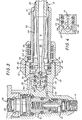
- a torch according to the invention (FIG. 1) comprises a handle 10 and a lance 11 which is fixed to this handle 10 by a threaded ring 12.
- the handle 10 comprises (FIGS. 1 and 3) a pair of conduits 13 and 14 adapted to be connected to two sources of gas 15 and 16.
- the conduit 13 is an oxygen conduit connected by a flexible hose 17 to an oxygen cylinder 15 while the conduit 14 is an acetylene conduit connected by a flexible hose 18 to an acetylene cylinder 16.
- the conduits 13 and 14 comprise tap means generally designated by 19. These tap means 19 more particularly comprise a button 20 for adjusting the overall oxygen and acetylene flow rate and a button 21 for dosing the proportion of oxygen and l acetylene in the mixture.
- 13A and 14A show the parts of the conduits 13 and 14 which are arranged downstream of the tap 19 and which are thus located at the front end 22 of the handle 10. This end 22 forms a threaded connection 23 for the ring 12 .
- the lance 11 ends with a spout 24 (FIG. 2) and comprises a bent tube 25 secured to a rear part or base 26, constituting an expandable tubular end piece.
- This rear part 26 of the lance 11 comprises, on the one hand, an axial injector 27 for oxygen and one or more lateral injectors 28 for acetylene.
- the two injectors 27 and 28 are connected to a mixing chamber 29, which is itself connected by a divergent 30 to the lance tube 25.
- This pre-expansion chamber 31 shows an expansion chamber of increasing section in one or more stages (two stages in the example shown in Figure 3).
- This pre-expansion chamber 31 is disposed between the oxygen injector 27 and the zone 32 by which the acetylene injectors 28 are connected to the mixing chamber 29.
- This pre-expansion chamber has the effect of limiting the risks of re-entry of flame.
- seals which are arranged between the rear part 26 of the lance 11 and the handle 10 and which are distributed on either side of the injectors 28.
- the end 13A of the conduit 13 terminates in a chamber 35 which is defined in the connector 22 of the handle around the rear end 26 of the lance 11 and which is limited by the seals sealing 34.
- This chamber 35 communicates with the oxygen injector 27.
- the front end 14A of the acetylene conduit 14 ends, in a similar manner, in a chamber 36 which is formed in the end of the connector 22 of the handle 10 and which is defined between the seals 33 and 34 in communicating with the acetylene injector 28.
- the two gases, oxygen and acetylene, respectively from the two bottles 15 and 16 pass through the pipes 17 and 18 in the conduits 13 and 14 then in the tap means 19 and pass through the ends 13A and 14A of the conduits 13 and 14 in chambers 35 and 36. Then they pass, for oxygen, into the injector 27 and the pre-expansion chamber 31, and, for acetylene, through the injectors 28 into the mixing chamber 29.
- the gas mixture passes through the divergent 30, passes through the tube 25 and reaches the spout 24 where the mixture forms a flame F.
- the two-gas torch according to the invention is provided with an internal anti-ignition device. .
- This internal anti-ignition device comprises a safety means forming a means of stopping or reducing the gas flow.
- the safety means generally designated by 37, is arranged between the tap means 19 and the injector means 27 and 28 and is associated with at least one of the two gases, namely in the example shown, oxygen.
- This safety means is made active in response to an untimely rise in temperature in a predetermined region R situated slightly downstream of the injector means 27 and 28. More particularly, this predetermined region where an untimely rise in temperature is detected located in the rear part 26 of the lance 11.
- the safety means 37 consists of a shutter having a seat element 38 and a closing element 39. These two elements are normally spaced from one another to allow the supply of one of the injectors , namely the injector 27 in the example shown, by one of the conduits, namely the oxygen conduit 13.
- the closing element 39 is adapted to approach the seat 37 by the effect of expansion thermal of the rear part 26 of the lance 11, in response to an untimely rise in temperature in the predetermined region R.
- the seat 38 of the shutter 37 is disposed at the front of the sleeve 10, while the closing element 39 of the shutter 37 is disposed at the rear of the lance 11.
- the lance 11 is mounted by longitudinal stop at 40 and preferably with a fixing by welding on the front end 41 of a bushing42.
- This socket 42 surrounds, in a spaced manner, the rear part 26 of the lance 11.
- the socket 42 is itself abutted longitudinally at 43 by its rear end 44 on the connector 23 of the handle 10.
- the stop 40 is provided downstream of the region R and significantly distant therefrom.
- the sleeve 42 constitutes a fixed outer envelope.
- the ring 12 for mounting the lance 11 on the connector 23 is screwed at .45 onto this connector 23 until it stops longitudinally at 46.
- a helical spring 47 is housed in the ring 12 around the bush 42 and is applied by one of its ends 48 to the ring 12 and by its other end 49 to the bush 42.
- the spring 47 has a predominant prestress on the passive resistances of the seals 33 and 34 but weak enough to avoid an irreparable compaction of the base 26 in the event of overheating.
- the spring 47 can be omitted if the shutter 37, instead of having elements 38, 39 metal on metal, has at least one of these two elements provided elastically deformable.
- the oxygen and acetylene supplied by the cylinders 15 and 16 pass through the conduits 13 and 14, pass through the tap 19 which has been adjusted for an overall flow suitable with a proportion also adjusted by the button 20, and pass through the injectors 27 and 28 to reach the mixing chamber 29 from which the mixture is directed by the divergent 30 in the lance tube 25 and leaves by the spout 24 producing flame F.
- the pre-expansion chamber 31 allows remarkable stability of the flame F outside the torch. It will also be understood that in normal operation and even if the work is intensive, the various parts, including the rear part 26 of the lance and the sleeve 42 are all at the same temperature so that the shutter 37 is open since the rear part 26 of the lance 11 expands in the same way as the bush 42.
- This rear part 26 therefore expands towards the rear, which tends to close at 38, 39 the safety shutter 37.
Landscapes
- Engineering & Computer Science (AREA)
- Chemical & Material Sciences (AREA)
- Combustion & Propulsion (AREA)
- Mechanical Engineering (AREA)
- General Engineering & Computer Science (AREA)
- Gas Burners (AREA)
Applications Claiming Priority (2)
| Application Number | Priority Date | Filing Date | Title |
|---|---|---|---|
| FR7930555A FR2471552A1 (fr) | 1979-12-13 | 1979-12-13 | Chalumeau a deux gaz muni d'un dispositif anti-inflammation interne |
| FR7930555 | 1979-12-13 |
Publications (2)
| Publication Number | Publication Date |
|---|---|
| EP0031279A1 EP0031279A1 (fr) | 1981-07-01 |
| EP0031279B1 true EP0031279B1 (fr) | 1983-09-14 |
Family
ID=9232728
Family Applications (1)
| Application Number | Title | Priority Date | Filing Date |
|---|---|---|---|
| EP19800401792 Expired EP0031279B1 (fr) | 1979-12-13 | 1980-12-12 | Chalumeau à deux gaz muni d'un dispositif anti-inflammation interne |
Country Status (3)
| Country | Link |
|---|---|
| EP (1) | EP0031279B1 (OSRAM) |
| DE (1) | DE3064850D1 (OSRAM) |
| FR (1) | FR2471552A1 (OSRAM) |
Families Citing this family (5)
| Publication number | Priority date | Publication date | Assignee | Title |
|---|---|---|---|---|
| JPS60111886A (ja) * | 1983-11-22 | 1985-06-18 | 新日本製鐵株式会社 | 溶射バ−ナ− |
| EP2843306A4 (en) | 2012-08-07 | 2015-12-02 | Hino Motors Ltd | BURNER FOR EXHAUST GAS CLEANING DEVICES |
| EP2843305B1 (en) | 2012-08-07 | 2017-10-11 | Hino Motors, Ltd. | Burner for exhaust gas purification devices |
| WO2014024942A1 (ja) | 2012-08-07 | 2014-02-13 | 日野自動車 株式会社 | バーナー |
| US9765662B2 (en) | 2012-08-13 | 2017-09-19 | Hine Motors, Ltd. | Burner |
Family Cites Families (6)
| Publication number | Priority date | Publication date | Assignee | Title |
|---|---|---|---|---|
| DE636528C (de) * | 1936-10-10 | I G Farbenindustrie Akt Ges | Mischduese aus hochhitzebestaendigem, gut waermeleitendem Metall fuer autogene Schweiss- oder Schneidbrenner | |
| DE704719C (de) * | 1938-04-17 | 1941-04-05 | Felix Damm | Schweiss- und Schneidbrenner |
| DE819081C (de) * | 1949-10-27 | 1951-10-29 | Felix Damm | Rueckschlagsicherer Injektor-Schweiss- und Schneidbrenner fuer den Betrieb mit einem Brenngas-Sauerstoff-Gemisch |
| FR1263362A (fr) * | 1960-04-25 | 1961-06-09 | Clapet anti-retour et anti-déflagrant pour appareils de soudure autogène | |
| FR2003488A1 (OSRAM) * | 1968-03-08 | 1969-11-07 | Messer Griesheim Gmbh | |
| CH543044A (de) * | 1970-09-30 | 1973-10-15 | Roth Alfred | Sicherungseinrichtung an Schweiss- oder Schneidbrenner gegen Überhitzung bei Flammenrückschlägen |
-
1979
- 1979-12-13 FR FR7930555A patent/FR2471552A1/fr active Granted
-
1980
- 1980-12-12 DE DE8080401792T patent/DE3064850D1/de not_active Expired
- 1980-12-12 EP EP19800401792 patent/EP0031279B1/fr not_active Expired
Also Published As
| Publication number | Publication date |
|---|---|
| FR2471552A1 (fr) | 1981-06-19 |
| DE3064850D1 (en) | 1983-10-20 |
| EP0031279A1 (fr) | 1981-07-01 |
| FR2471552B1 (OSRAM) | 1983-07-18 |
Similar Documents
| Publication | Publication Date | Title |
|---|---|---|
| CH619765A5 (OSRAM) | ||
| EP0031279B1 (fr) | Chalumeau à deux gaz muni d'un dispositif anti-inflammation interne | |
| EP1106212A1 (fr) | Lance à incendie | |
| CA2046363A1 (fr) | Bruleur catalytique | |
| FR2520090A1 (fr) | Bruleur a gaz de puissance reglable pour retracter les matieres thermo-retractables, notamment en vue de l'emballage de produits plus ou moins volumineux | |
| EP0235028A1 (fr) | Allumeur fixable dans la tuyère d'un propulseur | |
| FR2628291A1 (fr) | Dispositif pour bruler les cornes des animaux d'elevage | |
| WO1998059199A1 (fr) | Appareil a gaz du type desherbeur thermique | |
| EP0059137A1 (fr) | Dispositif d'allumage de carburant injecté dans un milieu gazeux en écoulement rapide | |
| FR2496520A1 (fr) | Perfectionnements apportes aux chalumeaux oxy-acetyleniques | |
| BE1006424A3 (fr) | Outil a main a dispositif d'allumage de gaz. | |
| EP0758438B1 (fr) | Dispositif de commande coordonnee de l'ecoulement d'au moins deux gaz, et br leur le comportant | |
| FR2699988A1 (fr) | Buse de chalumeau à gaz. | |
| EP0354099B1 (fr) | Générateur d'air chaud à gaz | |
| FR2719373A1 (fr) | Dispositif de propulsion à portées variables pour grenade anti-émeutes. | |
| CH616995A5 (OSRAM) | ||
| EP0234633B1 (fr) | Dispositif pour la stabilisation énergétique d'un générateur de gaz chauds | |
| EP0895026B1 (fr) | Procédé de suppression de la déflagration à l'extinction d'une flamme de combustion | |
| EP1504221A1 (fr) | Chalumeau et dispositif permettant de former un chalumeau | |
| FR2864206A3 (fr) | Bruleur pour un gril de barbecue a gaz | |
| FR3113717A1 (fr) | Dispositif d’injection de gaz pour un générateur d’air chaud | |
| EP0093642A2 (fr) | Buse perfectionnée à allumage par étincelles | |
| FR2708078A1 (fr) | Coupe-circuit de sécurité pour installations de manutention de fluides sous pression. | |
| BE636158A (OSRAM) | ||
| FR2786718A1 (fr) | Ensemble comprenant un chalumeau, des canalisations de gaz et des connecteurs de raccordement rapide |
Legal Events
| Date | Code | Title | Description |
|---|---|---|---|
| PUAI | Public reference made under article 153(3) epc to a published international application that has entered the european phase |
Free format text: ORIGINAL CODE: 0009012 |
|
| AK | Designated contracting states |
Designated state(s): DE GB IT SE |
|
| 17P | Request for examination filed |
Effective date: 19810720 |
|
| ITF | It: translation for a ep patent filed | ||
| GRAA | (expected) grant |
Free format text: ORIGINAL CODE: 0009210 |
|
| AK | Designated contracting states |
Designated state(s): DE GB IT SE |
|
| PG25 | Lapsed in a contracting state [announced via postgrant information from national office to epo] |
Ref country code: SE Effective date: 19830914 |
|
| REF | Corresponds to: |
Ref document number: 3064850 Country of ref document: DE Date of ref document: 19831020 |
|
| PLBE | No opposition filed within time limit |
Free format text: ORIGINAL CODE: 0009261 |
|
| STAA | Information on the status of an ep patent application or granted ep patent |
Free format text: STATUS: NO OPPOSITION FILED WITHIN TIME LIMIT |
|
| 26N | No opposition filed | ||
| PGFP | Annual fee paid to national office [announced via postgrant information from national office to epo] |
Ref country code: DE Payment date: 19841128 Year of fee payment: 5 |
|
| GBPC | Gb: european patent ceased through non-payment of renewal fee | ||
| PG25 | Lapsed in a contracting state [announced via postgrant information from national office to epo] |
Ref country code: DE Effective date: 19870901 |
|
| PG25 | Lapsed in a contracting state [announced via postgrant information from national office to epo] |
Ref country code: GB Free format text: LAPSE BECAUSE OF NON-PAYMENT OF DUE FEES Effective date: 19881118 |