EP0031096B1 - Optische Anordnung für einen Rauchmelder nach dem Lichtstreuungsprinzip - Google Patents
Optische Anordnung für einen Rauchmelder nach dem Lichtstreuungsprinzip Download PDFInfo
- Publication number
- EP0031096B1 EP0031096B1 EP80107833A EP80107833A EP0031096B1 EP 0031096 B1 EP0031096 B1 EP 0031096B1 EP 80107833 A EP80107833 A EP 80107833A EP 80107833 A EP80107833 A EP 80107833A EP 0031096 B1 EP0031096 B1 EP 0031096B1
- Authority
- EP
- European Patent Office
- Prior art keywords
- transmitter
- receiver
- optical
- test space
- radiation
- Prior art date
- Legal status (The legal status is an assumption and is not a legal conclusion. Google has not performed a legal analysis and makes no representation as to the accuracy of the status listed.)
- Expired
Links
Images
Classifications
-
- G—PHYSICS
- G08—SIGNALLING
- G08B—SIGNALLING SYSTEMS, e.g. PERSONAL CALLING SYSTEMS; ORDER TELEGRAPHS; ALARM SYSTEMS
- G08B17/00—Fire alarms; Alarms responsive to explosion
- G08B17/10—Actuation by presence of smoke or gases, e.g. automatic alarm devices for analysing flowing fluid materials by the use of optical means
- G08B17/103—Actuation by presence of smoke or gases, e.g. automatic alarm devices for analysing flowing fluid materials by the use of optical means using a light emitting and receiving device
- G08B17/107—Actuation by presence of smoke or gases, e.g. automatic alarm devices for analysing flowing fluid materials by the use of optical means using a light emitting and receiving device for detecting light-scattering due to smoke
-
- G—PHYSICS
- G01—MEASURING; TESTING
- G01N—INVESTIGATING OR ANALYSING MATERIALS BY DETERMINING THEIR CHEMICAL OR PHYSICAL PROPERTIES
- G01N21/00—Investigating or analysing materials by the use of optical means, i.e. using sub-millimetre waves, infrared, visible or ultraviolet light
- G01N21/17—Systems in which incident light is modified in accordance with the properties of the material investigated
- G01N21/47—Scattering, i.e. diffuse reflection
- G01N21/49—Scattering, i.e. diffuse reflection within a body or fluid
- G01N21/53—Scattering, i.e. diffuse reflection within a body or fluid within a flowing fluid, e.g. smoke
Definitions
- the principle of the smoke detector is based on the scattering of electromagnetic radiation from smoke particles that are located in a test room.
- the advantage of a uniform detection of large and small smoke particles is the pure use of backward scattering, i.e. the back radiation scattered at the particles at an acute angle / 3 to the optical transmitter.
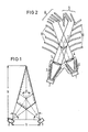
- the known arrangement has the disadvantage that the overall length is large in relation to the radiation or reception angle used. This can be explained by the fact that the beam guidance is only achieved through diaphragms. Backward scattering creates a tie-like overlap zone between the transmitter and receiver beam paths, which has the minimum required overall length of the arrangement according to the following relationship certainly. This means: h the overall length, b the distance of the transmitter from the receiver, ß the angle between the optical axes of the transmitter and receiver and ⁇ the beam opening angle and the reception opening angle.
- FIG. 1 of the drawing An optical transmitter 1 has a beam opening angle ⁇ , a receiver 2 has the beam opening angle ⁇ of the same size. Transmitter 1 and receiver 2 are spaced b apart. Their optical axes are at an angle ⁇ to each other. Their radiation or reception surfaces overlap in a tie-shaped area, which is shown in dashed lines in FIG. 1. This area is the cut surface of the test room in which the smoke particles to be detected are located. The tip of the overlap area facing away from the transmitter 1 and receiver 2 gives the necessary overall length h.
- the present invention has for its object to provide an optical arrangement for a smoke detector based on the light scattering principle, in which the overall length of the entire arrangement remains short while maintaining a small angle ⁇ for evaluating the backward radiation.
- the use of focusing elements ensures that large solid angles can be used on the transmitter and receiver side. A high intensity is thereby achieved.
- the diaphragms only have the task of intercepting the rays from undesirable scattering and reflection effects. It is advantageous if the diaphragms are directed at an acute angle to the common optical axis of the transmitter and receiver. If, in addition, the diaphragms are each bent at a larger angle, backscattering into the beam path is avoided on the one hand and greater mechanical strength of the diaphragm is achieved on the other side.
- the beam cone is surrounded in each case between the transmitter or receiver and the lens in front of it by a groove arrangement which serves as a light sump for radiation of a different direction than that in the beam cone corresponds to the parallel radiation of the test room. This prevents the non-parallel beams that are created in the lenses by multiple reflection from reaching the test space or reaching the receiver.
- FIG. 2 contains the illustration of an exemplary embodiment of an optical arrangement according to the invention.
- FIG. 2 shows a sectional view through an optical smoke detector according to the invention in the plane of an optical transmitter 1 and an optical receiver 2.
- the optical transmitter 1 directs electromagnetic radiation onto a test room 3, in which the smoke particles to be detected can be located.
- the direction of view of the transmitter 2 is also directed to this test room 3.
- Transmitter 1 and receiver 2 are at an acute angle ⁇ to each other.
- the non-multiply reflected or scattered rays of the transmitter 1 emerge approximately in parallel from the lens 4 into the test room 3 and, unless they are deflected by particle scattering, reach a light sump 8, where they are absorbed.
- the backward radiation scattered on the particles in the test space 3 arrives approximately parallel via the lens 5 in the receiver 2.
- the radiation scattered in the opposite direction reaches a light sump 9, where it is absorbed.
- the light marshes 8 and 9 each consist of four diaphragms. In the area of the supplementary angles on both sides of the angle ⁇ , five diaphragms each limit the beam paths between the transmitter 1 and light sump 8 or receiver 2 and light sump 9.
- All diaphragms 10 and 11 are directed at an acute angle to the common optical axis of transmitter 1 and receiver 2 and are each bent away from that axis. Apertures 10 and 11 only limit the beam paths and do not cut them. They have the sole task of intercepting rays from scatter and reflection effects.
- the acute angle to the common optical axis is favorable for hiding out incident radiation from the test space 3.
- the parallel beam guidance of an optical arrangement according to the invention has the advantage that the overall height perpendicular to the section plane shown in FIG. 2 can also be small. Apertures above and below the beam paths shown in FIG. 2 are not required.
Landscapes
- Physics & Mathematics (AREA)
- Analytical Chemistry (AREA)
- Chemical & Material Sciences (AREA)
- General Physics & Mathematics (AREA)
- Health & Medical Sciences (AREA)
- Emergency Management (AREA)
- Business, Economics & Management (AREA)
- Life Sciences & Earth Sciences (AREA)
- Biochemistry (AREA)
- General Health & Medical Sciences (AREA)
- Immunology (AREA)
- Pathology (AREA)
- Fire-Detection Mechanisms (AREA)
- Investigating Or Analysing Materials By Optical Means (AREA)
Description
- Die Erfindung betrifft eine optische Anordnung für einen Rauchmelder nach dem Lichtstreuungsprinzip mit den Merkmalen:
- a) ein optischer Sender ist auf einen Testraum gerichtet;
- b) ein optischer Empfänger ist im spitzen Winkel 73 zum Sender so auf den Testraum gerichtet, dass er die von den im Testraum befindlichen Partikeln gestreute Rückwärtsstrahlung empfängt;
- c) bei der Strahlungsführung für Sender und Empfänger werden optische Blenden verwendet.
- Eine solche optische Anordnung ist bekannt und beispielsweise in der DE-OS 2 630 843 beschrieben. Das Prinzip des Rauchmelders beruht auf der Streuung elektromagnetischer Strahlung an Rauchpartikeln, die sich in einem Testraum befinden. Vorteilhaft für ein gleichmässiges Erfassen von grossen und kleinen Rauchpartikeln ist die reine Verwendung der Rückwärtsstreuung, d.h. die in einem spitzen Winkel /3 zum optischen Sender an den Partikeln gestreute Rückwärtsstrahlung.
- Die bekannte Anordnung hat jedoch den Nachteil, dass die Baulänge im Verhältnis zum ausgenutzten Abstrahl- bzw. Empfangswinkel gross ist. Dies ist damit zu erklären, dass die Strahlführung ausschliesslich durch Blenden erreicht wird. Bei der Rückwärtsstreuung entsteht eine krawattenförmige Überlappungszone von Sender- und Empfängerstrahlengang, die die minimal erforderliche Baulänge der Anordnung nach folgender Beziehung

- An der Fig. 1 der Zeichnung soll dies verdeutlicht werden. Ein optischer Sender 1 besitzt einen Abstrahlöffnungswinkel α, ein Empfänger 2 besitzt den Empfangsöffnungswinkel α in derselben Grösse. Sender 1 und Empfänger 2 haben voneinander den Abstand b. Ihre optischen Achsen stehen zueinander im Winkel β. Ihre Abstrahl- bzw. Empfangsflächen überlappen sich in einem krawattenförmigen Bereich, der in der Fig. 1 gestrichelt dargestellt ist. Dieser Bereich ist die Schnittfläche des Testraums, in dem sich die nachzuweisenden Rauchpartikel befinden. Die vom Sender 1 und Empfänger 2 abgewandte Spitze des Überlappungsbereichs ergibt die notwendige Baulänge h.
- Der vorliegenden Erfindung liegt die Aufgabe zugrunde, eine optische Anordnung für einen Rauchmelder nach dem Lichtstreuungsprinzip anzugeben, bei dem unter Beibehalten eines kleinen Winkels ß für die Auswertung der Rückwärtsstrahlung die Baulänge der gesamten Anordnung gering bleibt.
- Zur Lösung dieser Aufgabe werden bei einer optischen Anordnung der eingangs genannten Art erfindungsgemäss folgende Merkmale vorgeschlagen:
- d) vor dem Sender und Empfänger befindet sich jeweils eine optische Linse, die die auf den Testraum gerichtete Strahlung zumindest angenähert parallel richtet bzw. die gestreute, zumindest angenähert parallele Rückwärtsstrahlung auf den Empfänger fokussiert;
- e) vor den Linsen im Bereich der Supplementwinkel zu /3 begrenzen Blenden die Strahlengänge von Sender und Empfänger;
- f) vom Sender und Empfänger gesehen jenseits des Testraums befindet sich jeweils ein Lichtsumpf.
- Bei einer erfindungsgemässen Anordnung ist trotz der Wahl des Winkels a- ≈ 0° durch die Verwendung fokussierender Elemente gewährleistet, dass grosse Raumwinkel sender- und empfängerseitig ausgenutzt werden können. Dadurch wird eine hohe Intensität erreicht. Die Blenden haben dabei ausschliesslich die Aufgabe, die Strahlen von unerwünschten Streu- und Reflexionseffekten abzufangen. Vorteilhaft ist, wenn die Blenden in einem spitzen Winkel zur gemeinsamen optischen Achse von Sender und Empfänger gegen diese gerichtet stehen. Wenn darüber hinaus die Blenden jeweils zu einem grösseren Winkel geknickt sind, werden auf der einen Seite Rückstreuungen in den Strahlengang vermieden und auf der anderen Seite eine grössere mechanische Festigkeit der Blenden erreicht.
- Nach einer weiteren vorteilhaften Ausgestaltung einer erfindungsgemässen Anordnung ist der Strahlenkegel jeweils zwischen dem Sender bzw. Empfänger und der davorliegenden Linse von einer Rillenanordnung umgeben, die als Lichtsumpf für Strahlung anderer Richtung dient als sie im Strahlenkegel der parallelen Strahlung des Testraums entspricht. Damit wird verhindert, dass die in den Linsen durch Mehrfachreflexion entstehenden nicht-parallelen Strahlen in den Testraum gelangen bzw. an den Empfänger gelangen.
- Ausser der in der Fig. 1 dargestellten prinzipiellen bekannten Anordnung enthält die Zeichnung in der Fig. 2 die Darstellung eines Ausführungsbeispiels einer erfindungsgemässen optischen Anordnung.
- Die Fig. 2 zeigt ein Schnittbild durch einen erfindungsgemässen optischen Rauchmelder in der Ebene eines optischen Senders 1 und eines optischen Empfängers 2. Der optische Sender 1 richtet elektromagnetische Strahlung auf einen Testraum 3, in dem sich die nachzuweisenden Rauchpartikel befinden können. Die Blickrichtung des Senders 2 ist ebenfalls auf diesen Testraum 3 gerichtet. Sender 1 und Empfänger 2 stehen zueinander in einem spitzen Winkel ß. Vor dem Sender 1 liegt eine optische Linse 4, vor dem Empfänger 2 eine optische Linse 5. Jeweils dazwischen ist eine optische Rillenanordnung 6 bzw. 7 angeordnet. Diese Rillenanordnung 6 und 7 umgeben den Strahlengang zwischen dem Sender 1 und der Linse 4 bzw. zwischen der Linse 5 und dem Empfänger 2 und dienen mit einem Belag von lichtabsorbierendem Material als Lichtsumpf. Die nicht mehrfach reflektierten oder gestreuten Strahlen des Senders 1 treten näherungsweise parallel aus der Linse 4 in den Testraum 3 und gelangen, sofern sie nicht durch Partikelstreuung abgelenkt werden, in einen Lichtsumpf 8, wo sie absorbiert werden. Die im Testraum 3 an den Partikeln gestreute Rückwärtsstrahlung gelangt annähernd parallel über die Linse 5 in dem Empfänger 2. Die in die entgegengesetzte Richtung gestreute Strahlung gelangt in einen Lichtsumpf 9, wo sie absorbiert wird. Die Lichtsümpfe 8 und 9 bestehen aus jeweils vier Blenden. Im Bereich der Supplementwinkel zu beiden Seiten des Winkels β begrenzen jeweils fünf Blenden die Strahlengänge zwischen Sender 1 und Lichtsumpf 8 bzw. Empfänger 2 und Lichtsumpf 9. Sie sind auf der einen Seite der innerhalb des Winkels /3 liegenden gemeinsamen optischen Achse mit 10 und auf der anderen Seite mit 11 bezeichnet. Sämtliche Blenden 10 und 11 stehen in einem spitzen Winkel zur gemeinsamen optischen Achse von Sender 1 und Empfänger 2 gegen sie gerichtet und sind jeweils in sich von der dieser Achse weg geknickt. Die Blenden 10 und 11 begrenzen lediglich die Strahlengänge und beschneiden sie nicht. Sie haben ausschliesslich die Aufgabe, Strahlen von Streu- und Reflexionseffekten abzufangen. Der spitze Winkel zur gemeinsamen optischen Achse ist günstig für ein Ausblenden von auftreffender Strahlung aus dem Testraum 3.
- Die parallele Strahlenführung einer erfindungsgemässen optischen Anordnung hat ausser dem Vorteil, dass die Baulänge des Rauchmelders gering gehalten werden kann, den Vorteil, dass auch die die Bauhöhe senkrecht zu der in der Fig. 2 dargestellten Schnittebene gering sein kann. Blenden oberhalb und unterhalb der Strahlengänge, die in der Fig. 2 dargestellt sind, sind nicht erforderlich.
Claims (4)
gekennzeichnet durch folgende Merkmale:
Priority Applications (1)
| Application Number | Priority Date | Filing Date | Title |
|---|---|---|---|
| AT80107833T ATE4754T1 (de) | 1979-12-20 | 1980-12-11 | Optische anordnung fuer einen rauchmelder nach dem lichtstreuungsprinzip. |
Applications Claiming Priority (2)
| Application Number | Priority Date | Filing Date | Title |
|---|---|---|---|
| DE2951459A DE2951459C2 (de) | 1979-12-20 | 1979-12-20 | Optische Anordnung für einen Rauchmelder nach dem Lichtstreuungsprinzip |
| DE2951459 | 1979-12-20 |
Publications (2)
| Publication Number | Publication Date |
|---|---|
| EP0031096A1 EP0031096A1 (de) | 1981-07-01 |
| EP0031096B1 true EP0031096B1 (de) | 1983-09-21 |
Family
ID=6089101
Family Applications (1)
| Application Number | Title | Priority Date | Filing Date |
|---|---|---|---|
| EP80107833A Expired EP0031096B1 (de) | 1979-12-20 | 1980-12-11 | Optische Anordnung für einen Rauchmelder nach dem Lichtstreuungsprinzip |
Country Status (13)
| Country | Link |
|---|---|
| US (1) | US4397557A (de) |
| EP (1) | EP0031096B1 (de) |
| AR (1) | AR221969A1 (de) |
| AT (1) | ATE4754T1 (de) |
| AU (1) | AU541994B2 (de) |
| BR (1) | BR8008326A (de) |
| CA (1) | CA1153230A (de) |
| DE (1) | DE2951459C2 (de) |
| DK (1) | DK149672C (de) |
| ES (1) | ES497972A0 (de) |
| MX (1) | MX149195A (de) |
| NO (1) | NO148691C (de) |
| ZA (1) | ZA807972B (de) |
Families Citing this family (44)
| Publication number | Priority date | Publication date | Assignee | Title |
|---|---|---|---|---|
| DE3233368A1 (de) * | 1982-09-08 | 1984-03-08 | Heimann Gmbh, 6200 Wiesbaden | Strahlungsrauchmelder |
| US4642471A (en) * | 1982-10-11 | 1987-02-10 | Cerberus Ag | Scattered radiation smoke detector |
| JPS6013449U (ja) * | 1983-03-31 | 1985-01-29 | ホーチキ株式会社 | 散乱光式煙感知器の検煙部構造 |
| DE3334545A1 (de) * | 1983-09-23 | 1985-04-04 | Siemens AG, 1000 Berlin und 8000 München | Optischer rauchmelder |
| GB9014015D0 (en) * | 1990-06-23 | 1990-08-15 | Dennis Peter N J | Improvements in or relating to smoke detectors |
| GB2270157B (en) * | 1992-08-28 | 1996-07-24 | Hochiki Co | Light scattering type smoke detector |
| CH684556A5 (de) * | 1992-09-14 | 1994-10-14 | Cerberus Ag | Optischer Rauchmelder. |
| GB2302943B (en) * | 1993-04-09 | 1997-05-21 | Hochiki Co | Light scattering type smoke detector with reduced zero-point detection level |
| JP2648560B2 (ja) * | 1993-04-09 | 1997-09-03 | ホーチキ株式会社 | 散乱光式煙感知器 |
| DE4414166C1 (de) * | 1994-04-22 | 1995-12-07 | Lorenz Mesgeraetebau | Verfahren und Vorrichtung zur Messung der Lichtstreuung an Partikeln |
| JPH08233736A (ja) * | 1995-02-27 | 1996-09-13 | Nohmi Bosai Ltd | 微粒子検出センサ |
| US6104945A (en) * | 1995-08-01 | 2000-08-15 | Medispectra, Inc. | Spectral volume microprobe arrays |
| US5713364A (en) * | 1995-08-01 | 1998-02-03 | Medispectra, Inc. | Spectral volume microprobe analysis of materials |
| US5813987A (en) * | 1995-08-01 | 1998-09-29 | Medispectra, Inc. | Spectral volume microprobe for analysis of materials |
| AUPN965896A0 (en) * | 1996-05-03 | 1996-05-30 | Vision Products Pty Ltd | The detection of airborne pollutants |
| US6847490B1 (en) | 1997-01-13 | 2005-01-25 | Medispectra, Inc. | Optical probe accessory device for use in vivo diagnostic procedures |
| US6826422B1 (en) | 1997-01-13 | 2004-11-30 | Medispectra, Inc. | Spectral volume microprobe arrays |
| ES2221946T3 (es) * | 1997-12-24 | 2005-01-16 | Siemens Building Technologies Ag | Detector de humo optico. |
| JP2002533142A (ja) | 1998-12-23 | 2002-10-08 | メディスペクトラ, インコーポレイテッド | サンプルの光学的試験のためのシステムおよび方法 |
| AU760402B2 (en) | 1998-12-23 | 2003-05-15 | Medispectra, Inc. | Optical methods and systems for cervical screening |
| DE19902319B4 (de) * | 1999-01-21 | 2011-06-30 | Novar GmbH, Albstadt-Ebingen Zweigniederlassung Neuss, 41469 | Streulichtbrandmelder |
| US6902935B2 (en) | 1999-12-15 | 2005-06-07 | Medispectra, Inc. | Methods of monitoring effects of chemical agents on a sample |
| US7260248B2 (en) | 1999-12-15 | 2007-08-21 | Medispectra, Inc. | Image processing using measures of similarity |
| US7187810B2 (en) | 1999-12-15 | 2007-03-06 | Medispectra, Inc. | Methods and systems for correcting image misalignment |
| US6839661B2 (en) | 2000-12-15 | 2005-01-04 | Medispectra, Inc. | System for normalizing spectra |
| DE10229239A1 (de) * | 2002-06-28 | 2004-01-15 | Robert Bosch Gmbh | Regensensor, insbesondere für ein Kraftfahrzeug |
| US7282723B2 (en) | 2002-07-09 | 2007-10-16 | Medispectra, Inc. | Methods and apparatus for processing spectral data for use in tissue characterization |
| US6933154B2 (en) | 2002-07-09 | 2005-08-23 | Medispectra, Inc. | Optimal windows for obtaining optical data for characterization of tissue samples |
| US7459696B2 (en) | 2003-04-18 | 2008-12-02 | Schomacker Kevin T | Methods and apparatus for calibrating spectral data |
| US7309867B2 (en) | 2003-04-18 | 2007-12-18 | Medispectra, Inc. | Methods and apparatus for characterization of tissue samples |
| US7136518B2 (en) | 2003-04-18 | 2006-11-14 | Medispectra, Inc. | Methods and apparatus for displaying diagnostic data |
| US6818903B2 (en) * | 2002-07-09 | 2004-11-16 | Medispectra, Inc. | Method and apparatus for identifying spectral artifacts |
| US7469160B2 (en) | 2003-04-18 | 2008-12-23 | Banks Perry S | Methods and apparatus for evaluating image focus |
| US7103401B2 (en) * | 2002-07-10 | 2006-09-05 | Medispectra, Inc. | Colonic polyp discrimination by tissue fluorescence and fiberoptic probe |
| US6768918B2 (en) | 2002-07-10 | 2004-07-27 | Medispectra, Inc. | Fluorescent fiberoptic probe for tissue health discrimination and method of use thereof |
| US7268881B2 (en) * | 2004-02-17 | 2007-09-11 | The Curators Of The University Of Missouri | Light scattering detector |
| US7151460B2 (en) * | 2005-01-10 | 2006-12-19 | Nokia Corporation | Electronic device having a proximity detector |
| CN101755204A (zh) | 2006-03-09 | 2010-06-23 | 全技术联合公司 | 蒸发光散射检测器 |
| US20110083493A1 (en) * | 2008-06-11 | 2011-04-14 | The Curators Of The University Of Missouri | Liquid Chromatography Detector and Flow Controller Therefor |
| KR20170030603A (ko) * | 2014-10-31 | 2017-03-17 | 파나소닉 아이피 매니지먼트 가부시키가이샤 | 입자 검출 센서, 더스트 센서, 연기 감지기, 공기 청정기, 환기팬 및 에어컨 |
| CN109427170B (zh) * | 2017-08-31 | 2021-08-06 | 西门子瑞士有限公司 | 烟感探测器 |
| CN110009863A (zh) * | 2019-04-19 | 2019-07-12 | 汉威科技集团股份有限公司 | 一种立式双光路感烟探测迷宫及其探测方法 |
| US11069224B1 (en) * | 2020-07-10 | 2021-07-20 | Everday Techology Co., Ltd. | Smoke detector and chamber |
| CN115875702A (zh) * | 2021-09-29 | 2023-03-31 | 佛山市顺德区美的洗涤电器制造有限公司 | 油烟传感器和厨房电器 |
Citations (2)
| Publication number | Priority date | Publication date | Assignee | Title |
|---|---|---|---|---|
| CH417405A (de) * | 1964-07-14 | 1966-07-15 | Cerberus Ag Werk Fuer Elektron | Vorrichtung zur Feststellung von Aerosolen in Luft |
| US4103997A (en) * | 1975-07-15 | 1978-08-01 | Matsushita Electric Works, Ltd. | Light scattering type smoke detector |
Family Cites Families (4)
| Publication number | Priority date | Publication date | Assignee | Title |
|---|---|---|---|---|
| US3555532A (en) * | 1968-10-29 | 1971-01-12 | Graham Stuart Corp | Vapor or particle detection device |
| NL7207630A (de) | 1972-06-06 | 1973-12-10 | ||
| US3916209A (en) * | 1973-07-24 | 1975-10-28 | Electro Signal Lab | Vaned baffle for optical smoke detector |
| CH600456A5 (de) * | 1976-12-23 | 1978-06-15 | Cerberus Ag |
-
1979
- 1979-12-20 DE DE2951459A patent/DE2951459C2/de not_active Expired
-
1980
- 1980-10-27 AR AR283011A patent/AR221969A1/es active
- 1980-12-10 US US06/215,061 patent/US4397557A/en not_active Expired - Lifetime
- 1980-12-11 AT AT80107833T patent/ATE4754T1/de not_active IP Right Cessation
- 1980-12-11 EP EP80107833A patent/EP0031096B1/de not_active Expired
- 1980-12-16 MX MX185268A patent/MX149195A/es unknown
- 1980-12-17 NO NO803842A patent/NO148691C/no unknown
- 1980-12-18 BR BR8008326A patent/BR8008326A/pt not_active IP Right Cessation
- 1980-12-18 DK DK539680A patent/DK149672C/da not_active IP Right Cessation
- 1980-12-19 AU AU65573/80A patent/AU541994B2/en not_active Ceased
- 1980-12-19 ZA ZA00807972A patent/ZA807972B/xx unknown
- 1980-12-19 CA CA000367175A patent/CA1153230A/en not_active Expired
- 1980-12-19 ES ES497972A patent/ES497972A0/es active Granted
Patent Citations (2)
| Publication number | Priority date | Publication date | Assignee | Title |
|---|---|---|---|---|
| CH417405A (de) * | 1964-07-14 | 1966-07-15 | Cerberus Ag Werk Fuer Elektron | Vorrichtung zur Feststellung von Aerosolen in Luft |
| US4103997A (en) * | 1975-07-15 | 1978-08-01 | Matsushita Electric Works, Ltd. | Light scattering type smoke detector |
Also Published As
| Publication number | Publication date |
|---|---|
| ATE4754T1 (de) | 1983-10-15 |
| AU541994B2 (en) | 1985-01-31 |
| NO148691B (no) | 1983-08-15 |
| AU6557380A (en) | 1981-06-25 |
| DK149672B (da) | 1986-09-01 |
| NO148691C (no) | 1983-11-23 |
| BR8008326A (pt) | 1981-07-07 |
| ZA807972B (en) | 1982-01-27 |
| DK539680A (da) | 1981-06-21 |
| US4397557A (en) | 1983-08-09 |
| NO803842L (no) | 1981-06-22 |
| ES8200496A1 (es) | 1981-11-01 |
| ES497972A0 (es) | 1981-11-01 |
| AR221969A1 (es) | 1981-03-31 |
| DK149672C (da) | 1987-04-13 |
| MX149195A (es) | 1983-09-21 |
| CA1153230A (en) | 1983-09-06 |
| DE2951459A1 (de) | 1981-07-02 |
| EP0031096A1 (de) | 1981-07-01 |
| DE2951459C2 (de) | 1984-03-29 |
Similar Documents
| Publication | Publication Date | Title |
|---|---|---|
| DE2951459C2 (de) | Optische Anordnung für einen Rauchmelder nach dem Lichtstreuungsprinzip | |
| DE60218074T2 (de) | Durchflusszytometer | |
| DE4216929A1 (de) | Einrichtung zur abbildung von streustrahlung | |
| EP0014825A2 (de) | Optische Anordnung für einen passiven Infrarot-Bewegungsmelder | |
| DE2046492C3 (de) | Rauchmelder | |
| DE69319184T2 (de) | Flüssigkeitsverschmutzungfühler | |
| DE2749494A1 (de) | Optischer rauchdetektor | |
| DE2447328A1 (de) | Verfahren zur bestimmung einer speziellen eigenschaft von in einem fluid suspendierten teilchen und vorrichtung zur durchfuehrung des verfahrens | |
| EP0556887B1 (de) | Anordnung zum Messen des Impulsübertragsspektrums von elastisch gestreuten Röntgenquanten | |
| CH688166A5 (de) | Rauchdetektor des Lichtstreuungs-Typs. | |
| DE3000034A1 (de) | Verfahren und vorrichtung zum messen der richtungsverteilungseigenschaften der von einem teilchen zurueckgestrahlten strahlungsenergie | |
| DE60226145T2 (de) | Einrichtung für ein optisches system | |
| DE3008183A1 (de) | Vorrichtung zum anzeigen von in einem gas suspendierten teilchen | |
| DE3000035A1 (de) | Vorrichtung und verfahren zum messen der streuung der durch teilchen erzeugten strahlungsenergie | |
| DE3143137C2 (de) | Reflexions-ausblendende, fokussierende optische Vorrichtung | |
| EP0660913B1 (de) | Signalleuchte | |
| DE2521433A1 (de) | Geraet zum messen des staubgehaltes eines gasstromes | |
| EP0025188A1 (de) | Optische Anordnung für einen Strahlungsdetektor | |
| DE3439287C2 (de) | Lasermikrostrahlanalysiergerät | |
| EP0105199B1 (de) | Strahlungsrauchmelder | |
| WO2020200691A1 (de) | Refraktometer und verfahren zur bestimmung des brechungsindex eines prozessmediums mit einem refraktometer | |
| EP0083431B1 (de) | Reflexlichtschranke mit erweitertem Funktionsbereich | |
| DE3525264C2 (de) | ||
| DE1256905B (de) | Optische Abtastvorrichtung | |
| DE102005029674A1 (de) | Blende für eine bildgebende Einrichtung |
Legal Events
| Date | Code | Title | Description |
|---|---|---|---|
| PUAI | Public reference made under article 153(3) epc to a published international application that has entered the european phase |
Free format text: ORIGINAL CODE: 0009012 |
|
| AK | Designated contracting states |
Designated state(s): AT BE CH FR GB IT LU NL SE |
|
| 17P | Request for examination filed |
Effective date: 19811030 |
|
| ITF | It: translation for a ep patent filed | ||
| GRAA | (expected) grant |
Free format text: ORIGINAL CODE: 0009210 |
|
| AK | Designated contracting states |
Designated state(s): AT BE CH FR GB IT LI LU NL SE |
|
| REF | Corresponds to: |
Ref document number: 4754 Country of ref document: AT Date of ref document: 19831015 Kind code of ref document: T |
|
| ET | Fr: translation filed | ||
| PLBE | No opposition filed within time limit |
Free format text: ORIGINAL CODE: 0009261 |
|
| STAA | Information on the status of an ep patent application or granted ep patent |
Free format text: STATUS: NO OPPOSITION FILED WITHIN TIME LIMIT |
|
| 26N | No opposition filed | ||
| ITTA | It: last paid annual fee | ||
| EPTA | Lu: last paid annual fee | ||
| EAL | Se: european patent in force in sweden |
Ref document number: 80107833.8 |
|
| PGFP | Annual fee paid to national office [announced via postgrant information from national office to epo] |
Ref country code: CH Payment date: 19950317 Year of fee payment: 15 |
|
| PGFP | Annual fee paid to national office [announced via postgrant information from national office to epo] |
Ref country code: GB Payment date: 19951123 Year of fee payment: 16 |
|
| PGFP | Annual fee paid to national office [announced via postgrant information from national office to epo] |
Ref country code: LU Payment date: 19951201 Year of fee payment: 16 |
|
| PGFP | Annual fee paid to national office [announced via postgrant information from national office to epo] |
Ref country code: BE Payment date: 19951213 Year of fee payment: 16 |
|
| PGFP | Annual fee paid to national office [announced via postgrant information from national office to epo] |
Ref country code: SE Payment date: 19951221 Year of fee payment: 16 |
|
| PGFP | Annual fee paid to national office [announced via postgrant information from national office to epo] |
Ref country code: FR Payment date: 19951226 Year of fee payment: 16 |
|
| PG25 | Lapsed in a contracting state [announced via postgrant information from national office to epo] |
Ref country code: LI Effective date: 19951231 Ref country code: CH Effective date: 19951231 |
|
| REG | Reference to a national code |
Ref country code: CH Ref legal event code: PL |
|
| PG25 | Lapsed in a contracting state [announced via postgrant information from national office to epo] |
Ref country code: LU Free format text: LAPSE BECAUSE OF NON-PAYMENT OF DUE FEES Effective date: 19961211 Ref country code: GB Effective date: 19961211 |
|
| PG25 | Lapsed in a contracting state [announced via postgrant information from national office to epo] |
Ref country code: SE Effective date: 19961212 |
|
| PG25 | Lapsed in a contracting state [announced via postgrant information from national office to epo] |
Ref country code: BE Effective date: 19961231 |
|
| BERE | Be: lapsed |
Owner name: HEIMANN G.M.B.H. Effective date: 19961231 |
|
| GBPC | Gb: european patent ceased through non-payment of renewal fee |
Effective date: 19961211 |
|
| PG25 | Lapsed in a contracting state [announced via postgrant information from national office to epo] |
Ref country code: FR Effective date: 19970829 |
|
| EUG | Se: european patent has lapsed |
Ref document number: 80107833.8 |
|
| REG | Reference to a national code |
Ref country code: FR Ref legal event code: ST |
|
| PGFP | Annual fee paid to national office [announced via postgrant information from national office to epo] |
Ref country code: AT Payment date: 19971126 Year of fee payment: 18 |
|
| PG25 | Lapsed in a contracting state [announced via postgrant information from national office to epo] |
Ref country code: AT Free format text: LAPSE BECAUSE OF NON-PAYMENT OF DUE FEES Effective date: 19981211 |
|
| PGFP | Annual fee paid to national office [announced via postgrant information from national office to epo] |
Ref country code: NL Payment date: 19991223 Year of fee payment: 20 |
|
| PG25 | Lapsed in a contracting state [announced via postgrant information from national office to epo] |
Ref country code: NL Free format text: LAPSE BECAUSE OF EXPIRATION OF PROTECTION Effective date: 20001211 |
|
| NLV7 | Nl: ceased due to reaching the maximum lifetime of a patent |
Effective date: 20001211 |