EP0030892A1 - Bac à plantes empilable - Google Patents
Bac à plantes empilable Download PDFInfo
- Publication number
- EP0030892A1 EP0030892A1 EP80401769A EP80401769A EP0030892A1 EP 0030892 A1 EP0030892 A1 EP 0030892A1 EP 80401769 A EP80401769 A EP 80401769A EP 80401769 A EP80401769 A EP 80401769A EP 0030892 A1 EP0030892 A1 EP 0030892A1
- Authority
- EP
- European Patent Office
- Prior art keywords
- grid
- container
- chimney
- appendage
- edges
- Prior art date
- Legal status (The legal status is an assumption and is not a legal conclusion. Google has not performed a legal analysis and makes no representation as to the accuracy of the status listed.)
- Withdrawn
Links
- XLYOFNOQVPJJNP-UHFFFAOYSA-N water Substances O XLYOFNOQVPJJNP-UHFFFAOYSA-N 0.000 claims abstract description 11
- 239000000463 material Substances 0.000 claims abstract description 5
- 238000000465 moulding Methods 0.000 claims description 8
- 230000000630 rising effect Effects 0.000 claims description 7
- 238000009423 ventilation Methods 0.000 claims description 4
- 238000005273 aeration Methods 0.000 abstract description 4
- 241000196324 Embryophyta Species 0.000 description 6
- 239000002390 adhesive tape Substances 0.000 description 2
- 239000002361 compost Substances 0.000 description 1
- 230000000994 depressogenic effect Effects 0.000 description 1
- 238000000605 extraction Methods 0.000 description 1
- 238000012986 modification Methods 0.000 description 1
- 230000004048 modification Effects 0.000 description 1
- 239000011347 resin Substances 0.000 description 1
- 229920005989 resin Polymers 0.000 description 1
- 239000002689 soil Substances 0.000 description 1
Images


Classifications
-
- A—HUMAN NECESSITIES
- A01—AGRICULTURE; FORESTRY; ANIMAL HUSBANDRY; HUNTING; TRAPPING; FISHING
- A01G—HORTICULTURE; CULTIVATION OF VEGETABLES, FLOWERS, RICE, FRUIT, VINES, HOPS OR SEAWEED; FORESTRY; WATERING
- A01G9/00—Cultivation in receptacles, forcing-frames or greenhouses; Edging for beds, lawn or the like
- A01G9/02—Receptacles, e.g. flower-pots or boxes; Glasses for cultivating flowers
-
- A—HUMAN NECESSITIES
- A01—AGRICULTURE; FORESTRY; ANIMAL HUSBANDRY; HUNTING; TRAPPING; FISHING
- A01G—HORTICULTURE; CULTIVATION OF VEGETABLES, FLOWERS, RICE, FRUIT, VINES, HOPS OR SEAWEED; FORESTRY; WATERING
- A01G27/00—Self-acting watering devices, e.g. for flower-pots
Definitions
- the present invention relates to improvements made to plant containers with automatic humidification and aeration, so that these containers, although complete, are stackable.
- Such known tanks generally comprise a container in which a grid is mounted to separate the upper cavity which is intended to receive the earth or other product, from the lower reserve which is intended to contain the water in which the wick must be immersed. grid is provided.
- a ventilation chimney running along the internal sides of the container communicates with the outside the permanent layer of air which is located between the water level and said grid; it also allows the filling of the reserve.
- a level indicator rod is guided in the chimney and cooperates with a float placed on the water.
- the present invention aims to re Edie m r this disadvantage by making them stackable drawer while retaining full in opposing any loss of parts and allowing for easy setup, convenient and fast.
- the grate and the chimney are a single piece of plastic material coming from molding, the chimney itself being constituted by an appendage articulated on one of the edges of the grid, capable of being applied against the said grid during storage and of being raised perpendicularly to the latter during assembly of the container, until its rising edges bear against the internal sides of the container .
- the zone of articulation of the chimney on the grate is situated in a cut-down angle of the latter;
- the container has a flared shape facilitating the stacking of several identical containers when the chimney is applied against the grid;
- the appendix intended to constitute the chimney presents a trapezoidal shape so that its rising edges can be applied in cutaway against the lower part of the internal sides of the container located under the flared part and opposite this, the appendix is extended by triangular flaps capable of being folded, along lines extending the previous edges, to extend parallel to the flanks of said flared part contiguous to the cutaway, the rising edges of said flaps then being applied against these flanks along strips support;
- the grid comprises, also from molding, a second appendage intended to constitute the cover of the chimney, this second appendage being articulated on the grid by at least one tearable tab and thus forming a temporary member for grasping the grid.
- this appendage constitutes a gripping element allowing the user to easily dislodge the grid and its equipment to then carry out the final assembly. Tray.
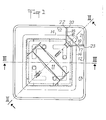
- the plant container comprises, as is well known, a container 1, a grid 2, a chimney 3 for ventilation and filling as well as a level indicator 4, all these elements generally being constituted by plastic material. die-cast.
- the grid 2 separates in the container when it is correctly mounted therein, an upper cavity 5 intended to receive the soil, the compost or other product in which the plants are rooted, from a resin ve lower 6 intended to contain the humidification water.
- the bottom 7 of the container 1 is integral with at least one overflow tube 8 which defines by overflow and flow to the bottom of this bottom the minimum level 9 of the water in the reserve.
- the chimney 3 allows, on the one hand, to pour the water for the filling of said reserve and on the other hand to renew the air of the permanent layer of air which is located under the grid 2 above the water level9 in this reserve; the aeration of the earth in the cavity 5 is obtained through the grid 2 thanks to the underlying layer 10 whose air is renewed thanks to the permanent communication established with the outside by the chimney 3.
- the moistening of this earth is obtained by means of a wick, not shown in the drawing, but extending over a bulge 11 with a double slope of the grid 2 so as to be in contact with said earth, the two hanging ends of the wick passing through the grid and plunging into the reserve water 6.
- the bins are made stackable first of all by the fact that the sides 12 are inclined in strong draft and converge upwards.
- the sides 12 of each of said containers have an upper flared part 13 which extends from an intermediate level 14 situated above the grid 2 to the edge free 15 of the container considered.
- the bins are also made stackable by the fact that during storage, all the elements which normally protrude into the cavity 5 are retracted in the manner described in the following.
- the chimney 3 free of cover extends at an angle of 45 ° between two contiguous and perpendicular sides 12; edges uprights 16 and 17 of this chimney are then applied against the sides 12 considered between the grid 2 and the intermediate level 14, from which the flared part 13 of the container rises; in this part 13, the chimney 3 comprises lateral flaps 18 and 19 which, instead of remaining at an angle, are made to be parallel to said sides 12; the rising edges 20 and 21 of these flaps are then applied against the flared part 13 between the level 14 and the free edge 15.
- the edges 16, 17, 20, 21 are normally in abutment against strips 22 and 23 projecting from the inside the container.
- the chimney 3, as described above with reference to FIG. l, is constituted by a single appendage 24 molded with the grid 2 and extending symmetrically with respect to a diagonal of the latter.
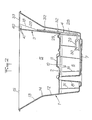
- the appendix 24, while being integral with the grid 2, is however articulated with respect to the latter, according to an articulation zone 25 situated in a depressed angle; in the example shown, the joint zone considered is obtained by causing a V-shaped groove to come into hollow, during molding, which marks in its thickness the grid 2 along a line intersecting its angle perpendicular to the diagonal of aforementioned symmetry.
- the appendage can be folded back, either to be folded down under the grid 2 and to be applied against the latter (representation in phantom in FIG.
- the appendage has a trapezoidal shape (Fig. 4) to correspond to the main cutaway portion of the chimney 3, its longitudinal edges 20 and 21 being intended to bear against the sides 12 between the fold line 25 of the grid 2 and the intermediate level 14; it is also important to note that the main cutaway section of appendix 24 is integral with the flaps.
- lateral 18 and 19 which have a triangular shape, extend from level 14 to the free edge 15 and are separated from this part in cross-section by fold lines 26 and 27 extending the edges 20 and 21; the edges 20 and 21 of the flaps 18 and 19 are intended, when these flaps are folded parallel to the sides 12, to bear against the flared part 13 of the container.
- the level indicator 4 is constituted by a rod 28 integral at its lower end with a fork 29 capable of pinching a float 30 to make it integral.
- the chimney 3 is reconstituted as indicated in the above but after having equipped it with the level indicator 4.
- the rod 28 of this indicator is sliding rise, in passers-by 32 coming from molding with the main cutaway part of appendix 24.
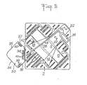
- Figs. 4 and 5 finally show that the grid 2 also came from molding with a second appendix 33 intended to constitute the chimney cover, as it appears in FIGS. 2 and 3.
- Appendix 33 has a pentagonal shape, that is to say to be more precise the shape of a square whose angle is cut. It therefore adapts perfectly to the cross section of the chimney flue at the free edge 15 of the container since its two adjoining long sides 34 and 35 correspond to the flared part 13 of the container, its short sides 36 and 37 parallel to the previous ones correspond to flaps 18 and 19 of the chimney and its biased side 38 corresponds to the cutaway portion of said chimney.
- the sides 36 to 38 are bordered by pairs of tabs 39 to 41, intended to fit on the upper edges of the flaps 18, 19 and the cutaway of the chimney.
- This appendage 33 is articulated by its biased side 38 on one side of the grid 2 by two tearable legs 42.
- the appendix 33 is integral with the grid and when the latter is mounted in the container to occupy the position of said stacking, said appendage 33 is applied against the corresponding internal flank 12 of the container. Consequently, appendix 33 does not interfere with stacking the bins, and yet the space it occupies is extremely interesting. Indeed, when it comes to unlocking the grid 2 to mount the chimney 3 and the indicator of level 28, appendix 33 forms a temporary gripping member on which one can pull. After extraction from the grid, appendix 33 is detached. When said grid is again locked in the container and the chimney is mounted, the cover 33 thus released can be placed on said chimney.
Landscapes
- Life Sciences & Earth Sciences (AREA)
- Environmental Sciences (AREA)
- Engineering & Computer Science (AREA)
- Water Supply & Treatment (AREA)
- Cultivation Receptacles Or Flower-Pots, Or Pots For Seedlings (AREA)
- Rigid Containers With Two Or More Constituent Elements (AREA)
- Packging For Living Organisms, Food Or Medicinal Products That Are Sensitive To Environmental Conditiond (AREA)
Applications Claiming Priority (2)
| Application Number | Priority Date | Filing Date | Title |
|---|---|---|---|
| FR7930515 | 1979-12-12 | ||
| FR7930515A FR2471133A1 (fr) | 1979-12-12 | 1979-12-12 | Bac a plantes empilable |
Publications (1)
| Publication Number | Publication Date |
|---|---|
| EP0030892A1 true EP0030892A1 (fr) | 1981-06-24 |
Family
ID=9232705
Family Applications (1)
| Application Number | Title | Priority Date | Filing Date |
|---|---|---|---|
| EP80401769A Withdrawn EP0030892A1 (fr) | 1979-12-12 | 1980-12-10 | Bac à plantes empilable |
Country Status (4)
| Country | Link |
|---|---|
| EP (1) | EP0030892A1 (OSRAM) |
| JP (1) | JPS5696633A (OSRAM) |
| AU (1) | AU6521980A (OSRAM) |
| FR (1) | FR2471133A1 (OSRAM) |
Cited By (5)
| Publication number | Priority date | Publication date | Assignee | Title |
|---|---|---|---|---|
| FR2648008A1 (fr) * | 1989-06-12 | 1990-12-14 | Sistac Sa B | Bac a plantes a reserve d'eau |
| FR2724813A1 (fr) * | 1994-09-26 | 1996-03-29 | Mj Ind | Recipient pour plante |
| EP0852110A3 (de) * | 1997-01-07 | 1999-03-31 | Gebr. Pöppelmann, Kunststoffwerk-Werkzeugbau | Pflanzgefäss |
| WO2004034770A1 (de) * | 2002-10-11 | 2004-04-29 | Torsten Kern | Pflanzenbehälter |
| CN108064597A (zh) * | 2016-11-15 | 2018-05-25 | 美商精耕系统控股有限责任公司 | 植物生长优化的种植系统 |
Families Citing this family (5)
| Publication number | Priority date | Publication date | Assignee | Title |
|---|---|---|---|---|
| JPS61115422A (ja) * | 1984-11-07 | 1986-06-03 | ザ デコ−ル コ−ポレ−シヨン プロプライエタリ− リミテツド | 植木鉢 |
| JPH0327408Y2 (OSRAM) * | 1984-12-22 | 1991-06-13 | ||
| AU595669B2 (en) * | 1987-01-23 | 1990-04-05 | Sebor Engineering (Proprietary) Limited | Plant pot |
| JPH0353823A (ja) * | 1989-07-20 | 1991-03-07 | Sanii Kk | 植木容器とこれを用いた栽培方法 |
| CN112628918A (zh) * | 2020-12-22 | 2021-04-09 | 南京国豪生态环境工程有限公司 | 一种利用绿化墙体清洁室内空气的方法 |
Citations (1)
| Publication number | Priority date | Publication date | Assignee | Title |
|---|---|---|---|---|
| FR2127242A6 (OSRAM) * | 1970-11-18 | 1972-10-13 | Grosfillex Sarl |
-
1979
- 1979-12-12 FR FR7930515A patent/FR2471133A1/fr active Granted
-
1980
- 1980-12-10 AU AU65219/80A patent/AU6521980A/en not_active Abandoned
- 1980-12-10 EP EP80401769A patent/EP0030892A1/fr not_active Withdrawn
- 1980-12-12 JP JP17474380A patent/JPS5696633A/ja active Pending
Patent Citations (1)
| Publication number | Priority date | Publication date | Assignee | Title |
|---|---|---|---|---|
| FR2127242A6 (OSRAM) * | 1970-11-18 | 1972-10-13 | Grosfillex Sarl |
Cited By (6)
| Publication number | Priority date | Publication date | Assignee | Title |
|---|---|---|---|---|
| FR2648008A1 (fr) * | 1989-06-12 | 1990-12-14 | Sistac Sa B | Bac a plantes a reserve d'eau |
| FR2724813A1 (fr) * | 1994-09-26 | 1996-03-29 | Mj Ind | Recipient pour plante |
| EP0852110A3 (de) * | 1997-01-07 | 1999-03-31 | Gebr. Pöppelmann, Kunststoffwerk-Werkzeugbau | Pflanzgefäss |
| WO2004034770A1 (de) * | 2002-10-11 | 2004-04-29 | Torsten Kern | Pflanzenbehälter |
| CN108064597A (zh) * | 2016-11-15 | 2018-05-25 | 美商精耕系统控股有限责任公司 | 植物生长优化的种植系统 |
| CN108064597B (zh) * | 2016-11-15 | 2022-09-16 | 美商精耕系统控股有限责任公司 | 植物生长优化的种植系统 |
Also Published As
| Publication number | Publication date |
|---|---|
| FR2471133A1 (fr) | 1981-06-19 |
| JPS5696633A (en) | 1981-08-04 |
| AU6521980A (en) | 1981-06-18 |
| FR2471133B1 (OSRAM) | 1982-01-08 |
Similar Documents
| Publication | Publication Date | Title |
|---|---|---|
| CH634973A5 (fr) | Boite a dejeuner pour enfants. | |
| EP0030892A1 (fr) | Bac à plantes empilable | |
| EP0385838A1 (fr) | Siège monolithique en matière plastique injectée | |
| EP0021963A1 (fr) | Pot destiné au marcottage aérien de végétaux | |
| LU86719A1 (fr) | Distributeurs de serviettes | |
| FR2556321A1 (fr) | Conteneur empilable de magasinage et de transport en matiere synthetique | |
| CH649594A5 (fr) | Chassis de voirie a couvercle basculant amovible. | |
| CH443950A (fr) | Dispositif de bec verseur | |
| FR2724813A1 (fr) | Recipient pour plante | |
| EP0179729A1 (fr) | Dispositif pour le rechargement automatique de sachets dans des récipients | |
| WO1994013367A1 (fr) | Dispositif pour le nettoyage des clubs de golf | |
| EP0270455A1 (fr) | Sac en matière plastique avec bande de fermeture adhésive | |
| EP1055364A1 (fr) | Dispositif de jardinière obtenue par rotomoulage. | |
| EP2687462B1 (fr) | Bac pour la collecte de déchets avec nervures anti-ruissellement | |
| EP0592270B1 (fr) | Cuve, porte-cuve et réceptacle à déchets, tel que corbeille à papiers, constitué par de telles pièces | |
| FR2699045A1 (fr) | Récipient pour plantes. | |
| WO1998011772A1 (fr) | Dispositif pour contenir et suspendre une charge d'un materiau, par exemple pot de fleur | |
| FR2561211A1 (fr) | Bac ou conteneur a couvercle inviolable | |
| FR2570677A1 (fr) | Emballage individuel pour bouteille constitue par un etui en matiere souple et plastique | |
| EP0519780B1 (fr) | Grille de ventilation et élément d'aération utilisant une telle grille | |
| FR2627687A1 (fr) | Protection temporaire pour les abattants de cuvette de w.c. | |
| EP1749762B1 (fr) | Ensemble d'au moins une cuve et d'un couvercle de protection. | |
| FR2821579A1 (fr) | Dispositif de support, dans le domaine de l'hygiene, notamment pour boites a gants d'examen | |
| EP0494822A1 (fr) | Bac jardinière à réserve d'eau pour usage urbain | |
| FR2704520A1 (fr) | Récipient en matière plastique moulée à anses de portage venues de moulage et procédé de fabrication dudit récipient. |
Legal Events
| Date | Code | Title | Description |
|---|---|---|---|
| PUAI | Public reference made under article 153(3) epc to a published international application that has entered the european phase |
Free format text: ORIGINAL CODE: 0009012 |
|
| AK | Designated contracting states |
Designated state(s): AT BE DE GB IT NL SE |
|
| STAA | Information on the status of an ep patent application or granted ep patent |
Free format text: STATUS: THE APPLICATION HAS BEEN WITHDRAWN |
|
| 18W | Application withdrawn |
Withdrawal date: 19811214 |
|
| RIN1 | Information on inventor provided before grant (corrected) |
Inventor name: PERRIN, MAURICE |