EP0030188A1 - Procédé de fabrication d'objets tels que des récipients à partir de résine et de fibrilles de bois et dispositif pour sa mise en oeuvre - Google Patents
Procédé de fabrication d'objets tels que des récipients à partir de résine et de fibrilles de bois et dispositif pour sa mise en oeuvre Download PDFInfo
- Publication number
- EP0030188A1 EP0030188A1 EP80401687A EP80401687A EP0030188A1 EP 0030188 A1 EP0030188 A1 EP 0030188A1 EP 80401687 A EP80401687 A EP 80401687A EP 80401687 A EP80401687 A EP 80401687A EP 0030188 A1 EP0030188 A1 EP 0030188A1
- Authority
- EP
- European Patent Office
- Prior art keywords
- mold
- flat
- matrix
- blank
- mixture
- Prior art date
- Legal status (The legal status is an assumption and is not a legal conclusion. Google has not performed a legal analysis and makes no representation as to the accuracy of the status listed.)
- Withdrawn
Links
- 238000000034 method Methods 0.000 title claims abstract description 15
- 229920005989 resin Polymers 0.000 title claims description 17
- 239000011347 resin Substances 0.000 title claims description 17
- 229920002522 Wood fibre Polymers 0.000 title 1
- 239000000203 mixture Substances 0.000 claims abstract description 34
- 230000006835 compression Effects 0.000 claims abstract description 23
- 238000007906 compression Methods 0.000 claims abstract description 23
- 238000004519 manufacturing process Methods 0.000 claims abstract description 9
- 238000001035 drying Methods 0.000 claims abstract description 7
- 239000011159 matrix material Substances 0.000 claims description 18
- 239000002023 wood Substances 0.000 claims description 12
- QEVHRUUCFGRFIF-MDEJGZGSSA-N reserpine Chemical compound O([C@H]1[C@@H]([C@H]([C@H]2C[C@@H]3C4=C(C5=CC=C(OC)C=C5N4)CCN3C[C@H]2C1)C(=O)OC)OC)C(=O)C1=CC(OC)=C(OC)C(OC)=C1 QEVHRUUCFGRFIF-MDEJGZGSSA-N 0.000 abstract 1
- 238000000465 moulding Methods 0.000 description 13
- 238000009434 installation Methods 0.000 description 11
- 229910000831 Steel Inorganic materials 0.000 description 7
- 239000010959 steel Substances 0.000 description 7
- 238000005452 bending Methods 0.000 description 3
- 239000011230 binding agent Substances 0.000 description 3
- 238000006243 chemical reaction Methods 0.000 description 3
- 235000013305 food Nutrition 0.000 description 3
- 238000004806 packaging method and process Methods 0.000 description 3
- 229920000728 polyester Polymers 0.000 description 3
- 238000011084 recovery Methods 0.000 description 3
- 238000009966 trimming Methods 0.000 description 3
- 238000011144 upstream manufacturing Methods 0.000 description 3
- 229920002678 cellulose Polymers 0.000 description 2
- 239000001913 cellulose Substances 0.000 description 2
- 238000010411 cooking Methods 0.000 description 2
- 230000006378 damage Effects 0.000 description 2
- 238000000151 deposition Methods 0.000 description 2
- 238000006073 displacement reaction Methods 0.000 description 2
- 239000011521 glass Substances 0.000 description 2
- 239000000463 material Substances 0.000 description 2
- 230000002093 peripheral effect Effects 0.000 description 2
- 230000000717 retained effect Effects 0.000 description 2
- 238000007789 sealing Methods 0.000 description 2
- 238000003860 storage Methods 0.000 description 2
- 239000004593 Epoxy Substances 0.000 description 1
- 229920000877 Melamine resin Polymers 0.000 description 1
- 241000237536 Mytilus edulis Species 0.000 description 1
- 102000007982 Phosphoproteins Human genes 0.000 description 1
- 108010089430 Phosphoproteins Proteins 0.000 description 1
- -1 Urea-Formalin Substances 0.000 description 1
- NIXOWILDQLNWCW-UHFFFAOYSA-N acrylic acid group Chemical group C(C=C)(=O)O NIXOWILDQLNWCW-UHFFFAOYSA-N 0.000 description 1
- 238000005520 cutting process Methods 0.000 description 1
- 238000010586 diagram Methods 0.000 description 1
- 238000009826 distribution Methods 0.000 description 1
- 238000005265 energy consumption Methods 0.000 description 1
- 238000000605 extraction Methods 0.000 description 1
- 239000004744 fabric Substances 0.000 description 1
- 235000014132 frozen ready meals Nutrition 0.000 description 1
- 239000004519 grease Substances 0.000 description 1
- 238000010438 heat treatment Methods 0.000 description 1
- JDSHMPZPIAZGSV-UHFFFAOYSA-N melamine Chemical compound NC1=NC(N)=NC(N)=N1 JDSHMPZPIAZGSV-UHFFFAOYSA-N 0.000 description 1
- 235000020638 mussel Nutrition 0.000 description 1
- 238000003825 pressing Methods 0.000 description 1
- 102000004169 proteins and genes Human genes 0.000 description 1
- 108090000623 proteins and genes Proteins 0.000 description 1
- 238000005096 rolling process Methods 0.000 description 1
- 230000035939 shock Effects 0.000 description 1
- 239000007858 starting material Substances 0.000 description 1
- 229920003002 synthetic resin Polymers 0.000 description 1
- 239000000057 synthetic resin Substances 0.000 description 1
- 229920001187 thermosetting polymer Polymers 0.000 description 1
- 238000007666 vacuum forming Methods 0.000 description 1
- 235000013311 vegetables Nutrition 0.000 description 1
- 125000000391 vinyl group Chemical group [H]C([*])=C([H])[H] 0.000 description 1
- 229920002554 vinyl polymer Polymers 0.000 description 1
- XLYOFNOQVPJJNP-UHFFFAOYSA-N water Substances O XLYOFNOQVPJJNP-UHFFFAOYSA-N 0.000 description 1
Images

Classifications
-
- B—PERFORMING OPERATIONS; TRANSPORTING
- B27—WORKING OR PRESERVING WOOD OR SIMILAR MATERIAL; NAILING OR STAPLING MACHINES IN GENERAL
- B27N—MANUFACTURE BY DRY PROCESSES OF ARTICLES, WITH OR WITHOUT ORGANIC BINDING AGENTS, MADE FROM PARTICLES OR FIBRES CONSISTING OF WOOD OR OTHER LIGNOCELLULOSIC OR LIKE ORGANIC MATERIAL
- B27N5/00—Manufacture of non-flat articles
- B27N5/02—Hollow articles
Definitions
- the present invention relates to a method of manufacturing objects such as containers from a mixture of resin and wood fibrils and more particularly from such a mixture obtained by dry process.
- a dry process is also known.
- the present invention aims to overcome these drawbacks.
- the subject of the invention is a process for the manufacture of objects such as containers, from a mixture of resin and wood fibrils obtained by the dry process, characterized in that one fills, in a filling station, using the mixture, a flat mold whose shape in plan corresponds to that of the development of the object to be manufactured, that the flat mold is brought to a precompression station, that the the mixture is precompressed flat inside the flat mold to obtain a flat blank, which is transferred to the flat blank above a die, that we fold the blank inside this die, that we compress the blank inside the die to obtain the finished object, that the the flat mold is returned to the filling station, the baking of the mixture of resin and wood fibrils in the matrix is carried out during compression, and the finished object is removed from the matrix.
- the mixture of resin and wood fibrils can, for example, be of the type described in French patent No. 78.25.291. Molding is possible with different percentages of the various resins that can be used.
- thermosetting binders such as Urea-Formalin, Epoxy, Polyester or an acrylic or vinyl binder may be used.
- This process allows in particular the production of truncated-pyramidal or truncated-conical containers with a depth ranging from a few millimeters to more than 150 millimeters. It is thus possible to manufacture containers with a conicity of the order of 8 to 10 ° and having at their upper part a rim allowing the sealing.
- the thickness of the walls of such containers can go down to 3 / 10ths of a millimeter.
- the container thus obtained is molded in a single operation without any trimming or subsequent finishing being necessary.
- porous or impermeable objects with water and grease and, with a starting material of the type of that described in the French patent mentioned above , heat-resistant objects, for example for making packaging for frozen ready meals.
- the method comprises a step consisting in the retraction of the edges of the flat mold after precompression to allow the transfer of the planar blank.
- the method can also include a step consisting in leveling the surface of the mixture of resin and wood fibrils placed in the first flat mold.
- a plurality of first flat molds are driven continuously one after the other from the filling station to the precompression station, then to the station for transferring the blank. flat with the second hollow mold.
- the present invention also relates to a device for implementing the method described above.
- this device is characterized in that it comprises at least one flat mold, means for filling this flat mold with a mixture of resin and wood fibrils obtained by dry process, means for precompressing the mixture. in the first flat mold, a die, means for transferring the blank formed from the precompressed mixture from the flat mold to the top of the die, means for folding the blank in the die, means for compressing the mixture in the matrix and means for driving the flat mold from the filling means to the precompression means, then from the precompression means to the transfer means.
- the means for folding the blank in the matrix comprise pushers capable of cooperating with the ejectors of the matrix to pinch and drive the blank to the bottom of the matrix.
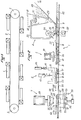
- FIG. 1 The installation shown in Figure 1 has eight molding units (1) as will be described in more detail with reference to Figure 2. Of course a different number of molding units could be provided.
- FIG. 1 also schematically represents a steel strip (2) whose function will be described below.
- This steel strip has two parallel strands along which the molding units (1) are arranged. These parallel strands are returned to two pulleys (3), one of which is driven at a suitable speed using a motor not shown.
- Figure 2 shows a molding unit in more detail.
- Each molding unit generally comprises a filling station (4), a precompression station (5), a station for opening the flat molds (6) and a compression station (7).
- Flat molds (8) described in more detail below circulate from one station to another of the unit (1) as well as from one unit to another.
- Each mold (8) essentially comprises a base plate (9) and two mold plates (10).
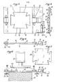
- Each mold plate (10) has a cutout (11), the cutouts (11) once joined having the cross-shaped appearance shown in FIG. 3.
- This shape is the development of the object to be produced which in this case is a food packaging of the "tray" type as shown on the left-hand side of FIG. 2, that is to say substantially a trunk of a pyramid provided at the upper part of its opening with a rim allowing the sealing.
- Each mold plate (10) is rotatably mounted on the bottom plate (9) using pins (12) passing through bearings (13) integral with the plate (9) and holes made in the plates ( 11). Furthermore, the plates (10) have beyond the axes (12) extensions (14) and the base plate (9) is cut as shown in (15) below the extensions (13).
- the flat mold (8) also includes a friction sole (16) at its upper part and a stop (17) at its lower part, the functions of which will be described below.
- an articulated lever (18) is mounted around an axis (19) perpendicular to the base plate (9) and carries on its outer side four permanent magnets (20). Finally the end of the lever (18) opposite the axis (19) is returned by a spring (21) connecting this end to a fixed point (22) of the base plate (9). This spring (21) has not been shown in Figure 5 for clarity.
- the base plate (9) also supports at its lower part four balls (23) mounted in cages (24) to allow the rolling of the flat mold (8).
- the base plate (9) and the mold plates (10) are preferably made of a material supporting repeated bending, for example in glass / polyester laminate.
- retractable (26) which, by cooperating with the stops (17) of the molds (8), can stop the progression of these molds.
- Braking members are also provided upstream of the retractable stops (26) to slow the molds (8) before they stop, in order to avoid shocks which could harm the homogeneity of the distribution of the mixture in the molds.
- These braking members can for example be simple rubber friction pads.
- the molds (8) are therefore driven as has just been described along the different stations of a molding unit in the direction of the arrows (27) in FIG. 2. These different stations will now be described in more detail.
- the station (4) for filling the molds (8) is shown on the right-hand side of FIG. (2).
- This position includes essen tially a storage hopper (28) intended to receive the bulk mixture of resin and wood fibrils.
- This storage hopper is equipped at its lower part with a pallet distributor (29) of known type.
- a recovery hopper (30) comprises at its lower part an exhaust orifice through which its content pours out and mixes with the product dispensed by the dispenser (29).
- the recovery hopper (30) has at its upper part a fine mesh fabric (31) and a pneumatic deflector (32).
- a conduit (33) opens into the axis of the deflector (32) and is supplied by a turbine (34).
- the turbine (34) sucks up via a conduit (35) and a hood (36) the excess product delivered raised by a rotary brush (37) which is itself driven by a motor unit / dimmer (38).
- the precompression station which is shown in more detail in FIG. 6 comprises a jack (39) to the rod of which is connected a punch (40) shown in plan in FIG. 7 and whose shape corresponds to that of the delimited enclosure by the walls of the cutouts (11) of the mold plates (10).
- a reaction plate (41) is arranged between the raceways (25).
- the height of the reaction plate (41) relative to the raceways (25) is such that when a mold (8) is placed below the punch (40) with its balls (23) on the raceways ( 25), the space (42) between the lower surface of the base plate (9) and the upper surface of the reaction plate (41) is minimal. It is important that when the punch (40) is pressed, the bending of the mold (8) does not lead to its destruction. It is for this purpose that the molds (8) are preferably made of a material such as laminate glass / polyester which can withstand repeated bending without being damaged.
- a stop (26) is provided at the precompression station (5) to stop the flat molds (8) so that the enclosure delimited by the mold plates (9) is located below the punch (40).
- a friction pad as mentioned above is also provided to slow down the molds (8) before the stops (26) and (17) are in contact in order to reduce the impact.
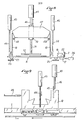
- the station for opening the flat molds (8) is shown in detail in FIGS. 8 and 9.
- This station comprises on the one hand, two jacks (43) whose rods (44) are provided for pressing on the extensions (14) of the mold plates (10). Furthermore, a third cylinder (45) has at the lower part of its rod (46) a member (47) capable of being placed across the path of the mold plates (10) when these are opened as will be described below. Finally, two guides (48) are also provided so that, when the flat molds (8) advance, their ends engage between the mold plates (10) of the flat molds (8).
- a fourth cylinder (70) is arranged as shown in FIG. 8, between the two cylinders (41).
- a plate (72) capable of coming to press flat on the blank before the rods (44) lift the mold plates (10 ).
- the plate (72) can be reassembled as soon as the mold plates (10) have been lifted in order to let the blank go flat with the mold (8).
- a retractable stop (26) is provided in a location as it can, by cooperating with the stop (17) of a mold (8), stop this mold in a position such that the rods (44) of the jacks (43) are vertical to the extensions (14) of the mold plates (10). Upstream of the stops (26) is arranged a friction pad to cooperate with the friction soles (16) of the molds (8) to prevent them from stopping suddenly.
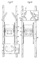
- FIGS 10 to 12 show in detail the compression station (7).
- This compression station essentially comprises a jack (49) carrying at its lower part a punch (50).
- Another cylinder (51) comprises a thrust plate (52) on which bear on one side the rod of the cylinder (51) and on the other side of the ejectors (53).
- the punch (50) carries, opposite the ejectors (53), pushers (54) retractable biased towards their position out of the punch (50) by elastic means not shown.
- the compression station further comprises, disposed on a support (55) a hollow heating mold (56) capable of cooperating with the punch (50), the internal shape (57) of which corresponds to that of the product to be obtained.
- the mold (56) is provided with holes (58) allowing the passage of the ejectors (53).
- the retractable pushers (54) protrude from the punch (50) by an amount sufficient to allow the blank pinched between these pushers and the ejectors (53) to reach the bottom of the mold cavity (57) (56) before the edge (50 ') of the punch (50) arrives at the edge (56') of the mold (56).
- the depth of the mold is greater than the development of the peripheral rim of the imprint, so that it is possible to obtain a molding not requiring subsequent trimming.
- the compression station also includes a stop (59), transversely substantially U-shaped as seen in FIGS. 12 to 15.
- This stop is arranged above the mold (56) at a height just sufficient to allow passage, between the mold (56) and the lower surface of the stop (59), flat molds (8).
- This stop (59) also comprises at its upstream part a centering cutout (60) whose function will be described below.
- the hopper (28) being loaded with a mixture of resin and wood fibrils, the pallet distributor (29) allows the passage of a predetermined flow rate of this mixture.
- the mixture falls on a flat mold (8) and consequently fills the enclosure delimited by the bottom plate (9) and the walls of the cutouts (11) of the mold plates (10).
- the jack (39) is then actuated so that the punch (40) compresses the mixture contained in the enclosure of the mold (8) to obtain a planar blank having sufficient hold.
- the jack (39) is then released, which causes the punch (40) to rise, after which the stop (26) is retracted so that the mold (8) is again driven by the steel strip (2).
- the jacks (43) are actuated so that their rods (44) by pushing the extensions (14) of the mold plates (10) cause the pivoting of these mold plates (10) and the opening of the mold.
- the plate (72) is then reassembled.
- the jack (45) is then actuated so that the member (47) is positioned as shown in Figure 8 thus preventing the fall of the mold plates (10) so that the rods (44) of the jacks (43) can be reassembled.
- the stop (26) of the mold opening station (6) is then retracted, so that the mold continues its path towards the compression station (7).
- the member (47) Before the rear end of the mold plates (10) exceeds the member (47), their front end engages on either side of the guides (48) so that these plates (10) cannot fall back .
- the member (47) can then be raised.
- the device is in the configuration shown in FIG. (13) with the planar blank at the top of the mold (56).
- the jack (49) is then actuated as shown in Figure 14 so that the pre-compressed planar blank is folded into the cavity (57) of the mold (56).
- the jack (51) is calibrated to offer resistance to the sinking of the ejectors (53) which makes it possible to pinch the pre-compressed flat blank between the ejectors and the pusher, and thus to keep it centered.
- the jack (49) being fully pushed back, the final object is molded between the punch (50) and the mold (56) as shown in FIG. 15, the pushers (54) being retracted inside the punch (50 ).
- the raising of the jack (49) is controlled by a timing circuit to determine the time cooking which can be of the order of 4 to 8 seconds.
- the cylinder (51) is actuated which ensures the extraction, via the ejectors (53), of the finished object (61) as shown in FIG. 2.
- the cylinders (39) of the precompression station (5), (43) and (45) of the mold opening station (6) and (49) of the compression station (7) are then actuated to simultaneously precompress the contained mixture in the mold (8) stopped at the precompression station, open the mold (8) stopped at the mold opening station, and ensure the compression of the pre-compressed flat blank (62) deposited on the mold (56).
- the jacks (39), (45) and (49) are raised and the two stops (26) of the precompression station (5) and the opening station of the molds (6) are retracted then immediately reset, the first to stop the first mold (8) on standby already filled, and the second to stop the mold (8) which has just been released by the stop (26) of the precompression (5).
- the jack (51) is actuated to extract from the mold (56) the finished object produced from the blank (62).
Landscapes
- Life Sciences & Earth Sciences (AREA)
- Engineering & Computer Science (AREA)
- Manufacturing & Machinery (AREA)
- Wood Science & Technology (AREA)
- Forests & Forestry (AREA)
- Casting Or Compression Moulding Of Plastics Or The Like (AREA)
Applications Claiming Priority (2)
| Application Number | Priority Date | Filing Date | Title |
|---|---|---|---|
| FR7929050A FR2470000A1 (fr) | 1979-11-26 | 1979-11-26 | Procede de fabrication d'objets tels que des recipients a partir de resine et de fibrilles de bois et dispositif pour sa mise en oeuvre |
| FR7929050 | 1979-11-26 |
Publications (1)
| Publication Number | Publication Date |
|---|---|
| EP0030188A1 true EP0030188A1 (fr) | 1981-06-10 |
Family
ID=9232082
Family Applications (1)
| Application Number | Title | Priority Date | Filing Date |
|---|---|---|---|
| EP80401687A Withdrawn EP0030188A1 (fr) | 1979-11-26 | 1980-11-26 | Procédé de fabrication d'objets tels que des récipients à partir de résine et de fibrilles de bois et dispositif pour sa mise en oeuvre |
Country Status (3)
| Country | Link |
|---|---|
| EP (1) | EP0030188A1 (show.php) |
| FR (1) | FR2470000A1 (show.php) |
| WO (1) | WO1981001534A1 (show.php) |
Families Citing this family (1)
| Publication number | Priority date | Publication date | Assignee | Title |
|---|---|---|---|---|
| US5108677A (en) * | 1988-10-17 | 1992-04-28 | John Ayres | Method of forming a sand base article using a decomposable binder and the article formed thereby |
Citations (1)
| Publication number | Priority date | Publication date | Assignee | Title |
|---|---|---|---|---|
| FR1380443A (fr) * | 1963-04-04 | 1964-12-04 | Ts P Konstrouctorscoe Buro Meb | Perfectionnement aux presses pour le moulage d'articles creux |
Family Cites Families (5)
| Publication number | Priority date | Publication date | Assignee | Title |
|---|---|---|---|---|
| FR1090834A (fr) * | 1952-11-15 | 1955-04-04 | Procédé et dispositif pour la fabrication d'éléments moulés | |
| US3373079A (en) * | 1964-09-18 | 1968-03-12 | Eastman | Pulp and fiber molding apparatus including resin application means |
| FR1436381A (fr) * | 1965-06-01 | 1966-04-22 | Weyerhaeuser Co | Procédé de production d'articles fibreux à trois dimensions pressés à chaud |
| FR1457930A (fr) * | 1965-12-14 | 1966-11-04 | Procédé pour presser des corps moulés d'assez grande longueur selon les trois coordonnées spatiales, dispositif et presse pour la mise en oeuvre du procédé | |
| FR2171583A5 (en) * | 1972-02-01 | 1973-09-21 | Gautier Raoul | Resin impregnated fibres moulding - using two presses |
-
1979
- 1979-11-26 FR FR7929050A patent/FR2470000A1/fr active Granted
-
1980
- 1980-11-26 WO PCT/FR1980/000168 patent/WO1981001534A1/fr not_active Ceased
- 1980-11-26 EP EP80401687A patent/EP0030188A1/fr not_active Withdrawn
Patent Citations (1)
| Publication number | Priority date | Publication date | Assignee | Title |
|---|---|---|---|---|
| FR1380443A (fr) * | 1963-04-04 | 1964-12-04 | Ts P Konstrouctorscoe Buro Meb | Perfectionnement aux presses pour le moulage d'articles creux |
Also Published As
| Publication number | Publication date |
|---|---|
| FR2470000A1 (fr) | 1981-05-29 |
| WO1981001534A1 (fr) | 1981-06-11 |
| FR2470000B1 (show.php) | 1982-06-25 |
Similar Documents
| Publication | Publication Date | Title |
|---|---|---|
| EP0115235B1 (fr) | Dispositif et procédé d'empilage et de chargement de feutres | |
| EP0142438A2 (fr) | Méthode et appareillage pour l'ensachage de matières fibreuses | |
| CA1078126A (fr) | Procede de moulage d'objets en particules agglomerees et dispositif pour la mise en oeuvre de ce procede | |
| EP0351289B1 (fr) | Machine de conditionnement en continu de produits en particulier alimentaires ou pharmaceutiques, dans des récipients en matière plastique | |
| EP0619773B1 (fr) | Procede et dispositif de fabrication de blocs de construction a partir d'un liant hydraulique tel que du platre, d'une charge inerte telle que du sable et d'eau | |
| EP0030188A1 (fr) | Procédé de fabrication d'objets tels que des récipients à partir de résine et de fibrilles de bois et dispositif pour sa mise en oeuvre | |
| FR2459000A1 (fr) | Machine a demouler, en particulier les jambons | |
| EP0006820B1 (fr) | Procédé de fabrication de pièces à base de particules de bois, dispositif pour la mise en oeuvre de ce procédé et pièces fabriquées | |
| CH411319A (fr) | Procédé de moulage par le vide et machine pour la mise en oeuvre de ce procédé | |
| EP0633837B1 (fr) | Appareil pour le compactage de blocs d'un produit ayant tendance a foisonner, et procede de compactage correspondant | |
| FR2478669A1 (fr) | Procede et machine pour la fabrication et l'emballage de boulets de charbon de bois | |
| FR2493104A1 (fr) | Unite de moulage de produits charcutiers et dispositif pour sa mise en oeuvre | |
| FR2729602A1 (fr) | Procede de moulage sous pression, et installation pour la mise en oeuvre de ce procede | |
| FR2478519A1 (fr) | Machine automatique pour la confection d'elements prefabriques en pate de ciment | |
| FR2466336A1 (fr) | Dispositifs d'alimentation par charges et d'obturation du manchon filtrant de presse a plateaux automatique | |
| FR2464190A1 (fr) | Dispositif d'obturation de recipients au moyen d'un couvercle en un materiau en feuille plastiquement deformable | |
| FR2569949A1 (fr) | Machine pour la fabrication de gaufres creuses | |
| FR2533540A1 (fr) | Appareil de manutention de moules pour aliments et installation le comportant, utilisables notamment pour la production de jambons cuits | |
| WO2007048751A1 (fr) | Dispositif de remplissage de nacelle avec des pastilles de combustible nucleaire et procede de remplissage mettant en œuvre un tel dispositif | |
| FR2624429A1 (fr) | Installation de thermoformage simultane d'au moins une rangee de recipients en matiere thermoplastique munis chacun d'une banderole decorative | |
| BE1001337A7 (fr) | Procede pour la preparation de matieres alimentaires a base de cereales expansees, dispositifs pour la mise en oeuvre de ce procede, et dispositif d'alimentation en matieres premieres. | |
| FR2612446A1 (fr) | Procede de fabrication d'objets par decoupe de matiere pateuse et dispositif pour la mise en oeuvre de ce procede | |
| FR2795916A1 (fr) | Presse pour jambons crus desosses | |
| FR2697228A1 (fr) | Dispositif et installation de compactage et d'ensachage d'articles en ouate de cellulose ou analogues. | |
| FR2644985A1 (fr) | Chaine automatique de production d'articles alimentaires moules multicouches de type " calisson " |
Legal Events
| Date | Code | Title | Description |
|---|---|---|---|
| PUAI | Public reference made under article 153(3) epc to a published international application that has entered the european phase |
Free format text: ORIGINAL CODE: 0009012 |
|
| AK | Designated contracting states |
Designated state(s): BE CH DE GB LU NL SE |
|
| 17P | Request for examination filed |
Effective date: 19811126 |
|
| STAA | Information on the status of an ep patent application or granted ep patent |
Free format text: STATUS: THE APPLICATION IS DEEMED TO BE WITHDRAWN |
|
| 18D | Application deemed to be withdrawn |
Effective date: 19831108 |