EP0030029B1 - Load positioning device, especially for waggons carrying vehicles - Google Patents
Load positioning device, especially for waggons carrying vehicles Download PDFInfo
- Publication number
- EP0030029B1 EP0030029B1 EP19800107497 EP80107497A EP0030029B1 EP 0030029 B1 EP0030029 B1 EP 0030029B1 EP 19800107497 EP19800107497 EP 19800107497 EP 80107497 A EP80107497 A EP 80107497A EP 0030029 B1 EP0030029 B1 EP 0030029B1
- Authority
- EP
- European Patent Office
- Prior art keywords
- scotch
- base plate
- section
- sole
- scotch body
- Prior art date
- Legal status (The legal status is an assumption and is not a legal conclusion. Google has not performed a legal analysis and makes no representation as to the accuracy of the status listed.)
- Expired
Links
Images
Classifications
-
- B—PERFORMING OPERATIONS; TRANSPORTING
- B61—RAILWAYS
- B61D—BODY DETAILS OR KINDS OF RAILWAY VEHICLES
- B61D45/00—Means or devices for securing or supporting the cargo, including protection against shocks
- B61D45/001—Devices for fixing to walls or floors
-
- B—PERFORMING OPERATIONS; TRANSPORTING
- B60—VEHICLES IN GENERAL
- B60P—VEHICLES ADAPTED FOR LOAD TRANSPORTATION OR TO TRANSPORT, TO CARRY, OR TO COMPRISE SPECIAL LOADS OR OBJECTS
- B60P3/00—Vehicles adapted to transport, to carry or to comprise special loads or objects
- B60P3/06—Vehicles adapted to transport, to carry or to comprise special loads or objects for carrying vehicles
- B60P3/07—Vehicles adapted to transport, to carry or to comprise special loads or objects for carrying vehicles for carrying road vehicles
- B60P3/073—Vehicle retainers
- B60P3/075—Vehicle retainers for wheels, hubs, or axle shafts
- B60P3/077—Wheel cradles, chocks, or wells
Definitions
- the present invention relates to a device for wedging vehicles on floors, in particular on railway vehicle transport equipment comprising a sole provided on its face in contact with the floor with protruding means intended to engage in a structure in hollow of the floor and a shoe body provided at the front with a wedging zone shaped to come into contact with a wheel of the vehicle to be propped up, said sole and said shoe body comprising means for the maintenance and the longitudinal guidance of the hoof body on the sole and means for locking the hoof body in stall position on the sole.
- the subject of the present invention is an adjustable wedging device, of the type defined above, designed so as not only to combine all the advantages of “fixed” wedging devices (simplicity, robustness, low cost price) and those of the adjustable wedging (wedging without play, simplicity of positioning) without having the disadvantages, but still offering additional advantages concerning the simplicity of removing the wedging device and the possibility of using the device for all vehicle models.
- the means for locking the hoof body in the chock position on the sole include a transverse tongue projecting obliquely downward and rearward on the hoof body and several transverse lights arranged one behind the other in the sole.
- the means for holding the hoof body on the sole include a transverse axis fixed to the sole so that its ends cooperate with the hoof body in the direction of holding with clearance the hoof body on the sole.
- the means projecting from the sole to engage in a hollow structure of the floor include two studs provided side by side on the rear part of the sole.
- the wedging device according to the invention while being composed of two parts which are movable with respect to one another and lockable with respect to each other, is devoid of any expensive mechanism, subject to failure , and can be used for all vehicle models, because for the removal of the wedging device, it suffices to lift the most accessible rear part of this device, using a foot-type lever - doe, to release the rear tensons from the floor, which frees the device as a whole.
- the shoe body has a transverse U-shaped profile, each wing projecting upwardly comprising an opening, each end of said transverse axis fixed to the sole cooperating in the direction of maintenance with play with the lower edge of the 'one of said openings.
- the core of the U-profile of the shoe body has a female boss and the sole has a corresponding male boss.
- a stirrup is fixed to the underside of the male boss of the sole, the hoof body has two openings for the passage of the two branches of this stirrup and the transverse axis is immobilized using a tubular untretoise and a pin between the branches of the stirrup, above the core of the U-profile of the shoe body.
- the wedging zone In order to avoid, in the event of a violent impact, that the wheel jumps over the wedging device, it is advantageous for the wedging zone to have an upper part in relief relative to the bearing face. In the event of a violent impact, this raised part is imprinted in the tire and thus brakes an untimely rotation of the latter.
- the locking tab is provided at the rear part of the hoof body and the lower edge of the opening provided in each wing of the U-profile of the hoof body is slightly inclined downwards from the front towards the back.
- the hoof body 4 in the form of a stamped U has a front support plate 5 welded to each fallen edge of the two wings of the U, it is provided with a handle 6.
- This hoof body 4 comprises on the base of U a female boss 10 allowing it to slide and guide itself on the male boss 11 of the sole 1 and between the reinforcements 1A-1B.
- the front support having a slight fold in its ends this avoids the possible slipping of the tire.
- an axis 7 is provided which is immobilized transversely by a tubular spacer 8 which is, with the axis 7, crossed by a pin 9.
- the stamped sole 1 provided with lateral reinforcements 1 A-1 B-1 C has an anterior zone with a male boss 11.
- this central boss are provided two longitudinal slots 12A and 12B for the passage of the two branches 3A-3B, respectively, of the stirrup 3 whose base is secured by welding to said zone.
- the latter also has a certain number of transverse slots 14, in this case six, in the sole embodiment (FIG. 4) for the passage of the tongue 13 provided on the basal zone 4B of the shoe body 4.
- two pins 2 used for the transverse immobilization of the shoe in the case of the use of the floor described in FR-A-2 450 177 deposits the 27 February 1979 as well as in grating type floors.
- the front face of the sole 1 is introduced in contact with the tire so that the studs 2 are in the housings or the grooves of the waves of the floor - the wedge being therefore immobilized, it is pushed towards the tire, with the foot or the hands the shoe 4 until the front support 5 comes to slightly compress the tire and the tongue 13 comes to fall into the corresponding lumen 14.
- nipples 2 The disengagement of nipples 2 from their housings or wave grooves is done by means of a crowbar-type lever bearing on the floor of the wagon.
- the distance between the pins 2 is advantageously chosen to cooperate with all the types of wagon floor currently known, but more particularly with the housings provided in the floors according to FR-A-2 450 177.
- the front support plate 105 has a projecting projection 105a in the vicinity of the upper edge of the shoe and is extended on the upper rear face of the shoe by a stiffening structure 105b which ends by a shoulder 105c for the attachment of the shims when they are released from the rolling surfaces where they are temporarily fixed.
- a reinforcement 114 intended to withstand the bending stresses when the shims are released from the rolling surfaces, while the front end 115 of said sole is appropriately bevelled, for s engage under the wheel to be chocked.
- This improved wedge also includes pins 102, a handle 106 for the shoe body 104.
- the universal chock shoe according to the invention adapts to tires of different widths as well as to twin tires, which the wedges currently known cannot do.
Landscapes
- Engineering & Computer Science (AREA)
- Transportation (AREA)
- Mechanical Engineering (AREA)
- Health & Medical Sciences (AREA)
- Public Health (AREA)
- Footwear And Its Accessory, Manufacturing Method And Apparatuses (AREA)
Description
La présente invention a pour objet un dispositif de calage de véhicules sur des planchers, notamment sur du matériel ferroviaire de transport de véhicules comprenant une semelle pourvue sur sa face en contact avec le plancher de moyens en saillie destinés à s'engager dans une structure en creux du plancher et un corps de sabot pourvu à l'avant d'une zone de calage conformée pour venir en contact avec une roue du véhicule à caler, ladite semelle et ledit corps de sabot comportant des moyens pour le maintien et le guidage longitudinal du corps de sabot sur la semelle et des moyens pour le verrouillage du corps de sabot en position de calage sur la semelle.The present invention relates to a device for wedging vehicles on floors, in particular on railway vehicle transport equipment comprising a sole provided on its face in contact with the floor with protruding means intended to engage in a structure in hollow of the floor and a shoe body provided at the front with a wedging zone shaped to come into contact with a wheel of the vehicle to be propped up, said sole and said shoe body comprising means for the maintenance and the longitudinal guidance of the hoof body on the sole and means for locking the hoof body in stall position on the sole.
En dehors des dispositifs de calage "fixes" comprenant un sabot immobilisé directement par rapport au plancher et n'admettant donc ni positionnement précis longitudinal et transversal, ni réglage de pression par rapport à la roue à caler, on connaît (DE-A-1 455 315) un dispositif de calage réglable tel que défini ci-dessus, avec un corps de sabot déplaçable longitudinalement sur une semelle accrochée au plancher. Sur ce dispositif connu, les moyens de verrouillage du corps de sabot par rapport à la semelle comprennent une crémaillère et un cliquet à ressort, ou des moyens équivalents à friction. Ces moyens de verrouillage, meme s'ils paraissent simples, augmentent sensiblement le prix de revient du dispositif de calage et surtout réduisent la fiabilité du dispositif. De plus, sur certains modèles de voitures, l'enlèvement de ce dispositif de calage connu peut présenter des difficultés.Apart from "fixed" wedging devices comprising a shoe immobilized directly relative to the floor and therefore admitting neither precise longitudinal and transverse positioning, nor pressure adjustment relative to the wheel to be chocked, we know (DE-A-1 455 315) an adjustable wedging device as defined above, with a hoof body which can be moved longitudinally on a soleplate attached to the floor. On this known device, the means for locking the shoe body relative to the sole include a rack and a spring pawl, or equivalent friction means. These locking means, even if they seem simple, significantly increase the cost price of the wedging device and above all reduce the reliability of the device. In addition, on certain car models, the removal of this known wedging device can present difficulties.
La présente invention a pour objet un dispositif de calage réglable, du type défini ci-dessus, conçu de manière à non seulement réunir tous les advantages des dispositifs de calage "fixe" (simplicité robustesse, faible prix de revient) et ceux du dispositif de calage réglable (calage sans jeu, simplicité de la mise en place) sans en présenter les inconvenients, mais encore d'offrir des avantages supplémentaires concernant la simplicité de l'enlèvement du dispositif de calage et la possibilité d'utilisation du dispositif pour tous les modèles de véhicules.The subject of the present invention is an adjustable wedging device, of the type defined above, designed so as not only to combine all the advantages of “fixed” wedging devices (simplicity, robustness, low cost price) and those of the adjustable wedging (wedging without play, simplicity of positioning) without having the disadvantages, but still offering additional advantages concerning the simplicity of removing the wedging device and the possibility of using the device for all vehicle models.
Sur le dispositif de calage conforme à l'invention, les moyens pour le verrouillage du corps de sabot en position de calage sur la semelle comprennent une languette transversale faisant saillie de façon oblique vers la bas et vers l'arrière sur le corps de sabot et plusieurs lumières transversales ménagées les unes derrière les autres dans la semelle. Les moyens de maintien du corps de sabot sur la semelle comprennent un axe transversal fixé à la semelle de manière que ses extrémités coopérent avec le corps de sabot dans le sens d'un maintien avec jeu du corps de sabot sur la semelle. Les moyens en saillie sur la semelle pour s'engager dans une structure en creux du plancher comprennent deux tenons prévus côte à côte sur la partie arrière de la semelle.On the wedging device according to the invention, the means for locking the hoof body in the chock position on the sole include a transverse tongue projecting obliquely downward and rearward on the hoof body and several transverse lights arranged one behind the other in the sole. The means for holding the hoof body on the sole include a transverse axis fixed to the sole so that its ends cooperate with the hoof body in the direction of holding with clearance the hoof body on the sole. The means projecting from the sole to engage in a hollow structure of the floor include two studs provided side by side on the rear part of the sole.
Le dispositif de calage conforme à l'invention, tout en étant composé de deux parties mobiles l'une par rapport à l'autre et verrouillables l'une par rapport à l'autre, est dépourvu de tout mécanisme couteux, sujet à des défaillance, et est utilisable pour tous les modèles de véhicules, du fait que pour l'enlèvement du dispositif de calage, il suffit de soulever la partie arrière la plus accessible de ce dispositif, à l'aide d'un levier du type pied-de-biche, pour dégager les tensons arrière du plancher, ce qui libère le dispositif dans son ensemble.The wedging device according to the invention, while being composed of two parts which are movable with respect to one another and lockable with respect to each other, is devoid of any expensive mechanism, subject to failure , and can be used for all vehicle models, because for the removal of the wedging device, it suffices to lift the most accessible rear part of this device, using a foot-type lever - doe, to release the rear tensons from the floor, which frees the device as a whole.
De préférence, le corps de sabot présente un profil transversal en U, chaque aile faisant saillie vers le haut comportant une ouverture, chaque extrémité dudit axe transversal fixée à la semelle coopérant dans le sens d'un maintien avec jeu avec le bord inférieur de l'une desdites ouvertures.Preferably, the shoe body has a transverse U-shaped profile, each wing projecting upwardly comprising an opening, each end of said transverse axis fixed to the sole cooperating in the direction of maintenance with play with the lower edge of the 'one of said openings.
En vue du guidage longitudinal du corps de sabot sur la semelle, il est avantageux qu'en coupe transversale, l'âme du profil en U du corps de sabot présente un bossage femelle et la semelle présente un bossage male correspondant.In view of the longitudinal guide of the shoe body on the sole, it is advantageous that in cross section, the core of the U-profile of the shoe body has a female boss and the sole has a corresponding male boss.
Suivant un mode de réalisation préféré des moyens de maintien du corps de sabot sur la semelle, un étrier est fixé à la face inférieure du bossage mâle de la semelle, le corps de sabot présente deux lumières pour le passage des deux branches de cet étrier et l'axe transversal est immoblisé à l'aide d'une untretoise tubulaire et d'une goupille entre les branches de l'étrier, au-dessus de l'âme du profil en U du corps de sabot.According to a preferred embodiment of the means for holding the hoof body on the sole, a stirrup is fixed to the underside of the male boss of the sole, the hoof body has two openings for the passage of the two branches of this stirrup and the transverse axis is immobilized using a tubular untretoise and a pin between the branches of the stirrup, above the core of the U-profile of the shoe body.
Afin d'éviter, en cas de choc violent, que la roue saute par-dessus le dispositif de calage, il est avantageux que la zone de calage présente une partie supérieure en relief par rapport à la face d'appui. En cas de choc violent, cette partie en relief s'imprime dans le pneu et freine ainsi une rotation intempestive de ce dernier.In order to avoid, in the event of a violent impact, that the wheel jumps over the wedging device, it is advantageous for the wedging zone to have an upper part in relief relative to the bearing face. In the event of a violent impact, this raised part is imprinted in the tire and thus brakes an untimely rotation of the latter.
De préference, le languette de verrouillage est prévue à la partie arrière du corps de sabot et le bord inférieure de l'ouverture prévue dans chaque aile du profil en U du corps de sabot est légèrement inclinée vers le bas de l'avant vers l'arrière.Preferably, the locking tab is provided at the rear part of the hoof body and the lower edge of the opening provided in each wing of the U-profile of the hoof body is slightly inclined downwards from the front towards the back.
L'invention sera mieux comprise à la lecture de la description non limitative suivie de deux formes de réalisation de dispositif de calage, en référence au dessin annexé sur lequel:
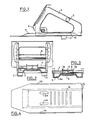
- - la figure 1 est une vue latérale d'une forme de réalisation du sabot de calage selon l'invention;
- - la figure 2 est une vue par l'arrière du sabot de la figure 1;
- -la figure 3 est une coupe transversale au niveau d'articulation du corps de sabot à la semelle;
- - la figure 4 est une vue plane de la semelle de sabot; et,
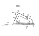
- - la figure 5 est une vue latérale d'une autre forme de réalisation de sabot de calage selon l'invention.
- - Figure 1 is a side view of an embodiment of the wedging shoe according to the invention;
- - Figure 2 is a rear view of the shoe of Figure 1;
- FIG. 3 is a cross section at the level of articulation of the shoe body to the sole;
- - Figure 4 is a plan view of the shoe sole; and,
- - Figure 5 is a side view of another embodiment of the wedging shoe according to the invention.
Le corps de sabot 4 en forme de U embouti présente une tôle d'appui frontale 5 soudée sur chaque bord tombé des deux ailes de l'U, il est muni d'une poignée 6. Ce corps de sabot 4 comporte sur la base de l'U un bossage femelle 10 lui permettant de coulisser et de se guider sur le bossage mâle 11 de la semelle 1 et entre les renforts 1A-1B. L'appui frontal possédant un léger pli dans ses extrémités ceci évite le glissement éventuel du pneumatique.The hoof body 4 in the form of a stamped U has a
Pour éviter une désolidarisation du corps 4 de la semelle 1, il est prévu un axe 7 immobilisé transversalement par une entretoise tubulaire 8 qui est, avec l'axe 7, traversée par une goupille 9.To avoid separation of the body 4 from the sole 1, an
Cet axe et entretoise libres en rotation passent dans un étrier 3 qui est soudé à l'intérieur du bossage 11 de la semelle 1.This axis and spacer which are free to rotate pass through a stirrup 3 which is welded inside the
La semelle 1 emboutie pourvue de renforts latéraux 1 A-1 B-1 C présente une zone antérieure avec un bossage mâle 11. Dans ce bossage central sont prévues deux lumières longitudinales 12A et 12B pour le passage des deux branches 3A-3B, respectivement, de l'étrier 3 dont la base est solidarisée par soudure à ladite zone.The stamped sole 1 provided with lateral reinforcements 1 A-1 B-1 C has an anterior zone with a
Cette dernière présente également un certain nombre de lumières transversale 14, dans le cas présent six, dans la forme de réalisation de semelle (fig. 4) pour le passage de la languette 13 prévue sur la zone basale 4B du corps de sabot 4.The latter also has a certain number of
Sur la face inférieure des zones latérales de la semelle sont solidarisés, par exemple par soudure, deux tétons 2 servant à l'immobilisation transversale du sabot dans le cas de l'utilisation du plancher décrit dans FR-A-2 450 177 dépose le 27 Février 1979 ainsi que dans les planchers de type caillebotis.On the underside of the lateral zones of the sole are joined, for example by welding, two
Le dispositif de calage est utilisable de la façon suivante:
- Avant introduction de la cale de type sabot, il faut prendre soin de mettre le sabot 4 dans la position la plus arrière de la semelle 1.
- Before inserting the shoe type wedge, care must be taken to put shoe 4 in the rearmost position of sole 1.
On introduit la face avant de la semelle 1 au contact du pneumatique de façon que les tétons 2 se trouvent dans les logements ou les rainures des ondes du plancher-la cale étant de ce fait immobilisée on pousse vers le pneumatique, avec le pied ou les mains le sabot 4 jusqu'à ce que l'appui frontal 5 vienne légèrement comprimer le pneumatique et que la languette 13 vienne tomber dans la lumière 14 correspondante.The front face of the sole 1 is introduced in contact with the tire so that the
La languette 13 formant un angle et pénétrant dans la lumière transversale 14 de la semelle 1, on obtient avec la pression des pneumatiques un verrouillage permanent.The
Le désengagement de tétons 2 de leurs logement ou rainures d'ondes se fait au moyen d'un levier du genre pied de biche prenant appui sur le plancher du wagon.The disengagement of
La distance entre les tétons 2 est avantageusement choisie pour coopérer avec tous les types de plancher de wagons actuellement connus, mais plus particulièrement avec les logements prévus dans les planchers selon FR-A-2 450 177.The distance between the
Dans la forme de réalisation de la figure 5, la tôle d'appui frontale 105 présente une saillie venue de formage 105a au voisinage du bord supérieur du sabot et se prolonge sur la face supérieure arrière du sabot par une structure de raidissement 105b qui se termine par une épaulement 105c pour l'acrochement des cales lors de leur dégagement des surfaces de roulement où elles sont temporairement fixées.In the embodiment of FIG. 5, the
A l'extrémité arrière de la semelle de cale est prévu un renforcement 114 destiné à supporter les contraintes de flexion lors du dégagement des cales des surfaces de roulement, tandis que l'extrémité avant 115 de ladite semelle est biseautée de façon appropriée, pour s'engager sous la roue à caler.At the rear end of the shim sole is provided a
Cette cale améliorée comporte également des tétons 102, une poignée 106 pour le corps de sabot 104.This improved wedge also includes
Le sabot universal de calage selon l'invention s'adapte aux pneus de différentes largeurs ainsi qu'aux pneus jumelés, ce que les cales actuellement connues ne peuvent pas faire.The universal chock shoe according to the invention adapts to tires of different widths as well as to twin tires, which the wedges currently known cannot do.
Claims (6)
Applications Claiming Priority (2)
| Application Number | Priority Date | Filing Date | Title |
|---|---|---|---|
| FR7929669 | 1979-12-03 | ||
| FR7929669A FR2470718A1 (en) | 1979-12-03 | 1979-12-03 | LOAD SETTING DEVICE, IN PARTICULAR FOR TRANSPORT CARS OF VEHICLES |
Publications (2)
| Publication Number | Publication Date |
|---|---|
| EP0030029A1 EP0030029A1 (en) | 1981-06-10 |
| EP0030029B1 true EP0030029B1 (en) | 1985-05-29 |
Family
ID=9232335
Family Applications (1)
| Application Number | Title | Priority Date | Filing Date |
|---|---|---|---|
| EP19800107497 Expired EP0030029B1 (en) | 1979-12-03 | 1980-12-01 | Load positioning device, especially for waggons carrying vehicles |
Country Status (3)
| Country | Link |
|---|---|
| EP (1) | EP0030029B1 (en) |
| DE (1) | DE3070716D1 (en) |
| FR (1) | FR2470718A1 (en) |
Cited By (1)
| Publication number | Priority date | Publication date | Assignee | Title |
|---|---|---|---|---|
| DE10307598A1 (en) * | 2003-02-22 | 2004-09-02 | Alstom Lhb Gmbh | Wedge for securing reels of paper on railway trucks comprises base plate whose upper surface forms rack, along which hollow wedge can move in steps, hook which locks wedge in desired position being mounted inside it |
Families Citing this family (4)
| Publication number | Priority date | Publication date | Assignee | Title |
|---|---|---|---|---|
| FR2607763B1 (en) * | 1986-12-03 | 1989-03-31 | Gefco | SETTING DEVICE, ESPECIALLY OF A MOTOR VEHICLE ON MEANS OF TRANSPORT |
| GB2274691A (en) * | 1993-01-30 | 1994-08-03 | Ian Frank Edwin Perrett | Self sustaining wheel chocks |
| US5627352A (en) * | 1994-09-28 | 1997-05-06 | Toyoda Gosei Co., Ltd. | Steering wheel |
| DE102004006800B4 (en) * | 2004-02-11 | 2008-04-24 | Railion Deutschland Ag | retaining key |
Family Cites Families (9)
| Publication number | Priority date | Publication date | Assignee | Title |
|---|---|---|---|---|
| FR1020804A (en) * | 1952-01-24 | 1953-02-11 | Sncf | Platform for the transport of vehicles |
| FR79785E (en) * | 1960-08-03 | 1963-01-25 | Venissieux Atel | Removable wedge for loading road vehicles onto wagons or other transport vehicles |
| FR1272541A (en) * | 1960-08-03 | 1961-09-29 | Venissieux Atel | Removable wedge for loading road vehicles onto wagons or other transport vehicles |
| DE1455315A1 (en) * | 1961-11-02 | 1969-01-23 | Die Costamasnaga S P A Off | Quick lock device for wheel chocks or the like on railroad cars. motor vehicles to be transported |
| FR1381055A (en) * | 1963-01-29 | 1964-12-04 | Graaff J Niedersaechs Waggon | Wheel chock removably connected to the loading troughs of automobile transport vehicles |
| FR1510029A (en) * | 1966-12-05 | 1968-01-19 | Venissieux Atel | Wedge for vehicle mounted on means of transport |
| DE7106080U (en) * | 1971-02-18 | 1971-07-29 | Krupp F Huettenwerke Ag | SHEET COIL FIXING DEVICE FOR TRANSPORT VEHICLES |
| FR2421768A1 (en) * | 1978-04-03 | 1979-11-02 | Venissieux Atel | Vehicle wheel chock or wedge - has guide with elastic shock absorber and base with fixing down teeth |
| FR2450177A1 (en) * | 1979-02-27 | 1980-09-26 | Francon & Cie Sa | LOAD SETTING DEVICE, IN PARTICULAR FOR TRANSPORT VEHICLE FLOORS, AND VEHICLE FLOORS AND THE LIKE COMPRISING THIS DEVICE |
-
1979
- 1979-12-03 FR FR7929669A patent/FR2470718A1/en active Granted
-
1980
- 1980-12-01 EP EP19800107497 patent/EP0030029B1/en not_active Expired
- 1980-12-01 DE DE8080107497T patent/DE3070716D1/en not_active Expired
Cited By (1)
| Publication number | Priority date | Publication date | Assignee | Title |
|---|---|---|---|---|
| DE10307598A1 (en) * | 2003-02-22 | 2004-09-02 | Alstom Lhb Gmbh | Wedge for securing reels of paper on railway trucks comprises base plate whose upper surface forms rack, along which hollow wedge can move in steps, hook which locks wedge in desired position being mounted inside it |
Also Published As
| Publication number | Publication date |
|---|---|
| EP0030029A1 (en) | 1981-06-10 |
| FR2470718B1 (en) | 1983-06-17 |
| FR2470718A1 (en) | 1981-06-12 |
| DE3070716D1 (en) | 1985-07-04 |
Similar Documents
| Publication | Publication Date | Title |
|---|---|---|
| EP0214061A1 (en) | Plastic-rollers skate | |
| FR2891515A1 (en) | Car battery mounting system comprises tray, into which battery fits, with ribs which lodge over lugs near base of battery, one rib having lug on it which can be moved to locking position by handle and fixed by wedge between lug and handle | |
| EP0030029B1 (en) | Load positioning device, especially for waggons carrying vehicles | |
| US2973224A (en) | Wheelbarrow | |
| EP1621237B1 (en) | Set for binding a shoe on a glide board | |
| US2579853A (en) | Wheel manipulating tool | |
| FR2606716A1 (en) | CARRIER UNITARY ARM FOR SUPPORTING A VEHICLE THROUGH ITS WHEELS | |
| EP0311543A1 (en) | Lashing strap for holding wheels of a vehicle on a loading surface | |
| US2816627A (en) | Retractable wheel chock | |
| FR2489761A1 (en) | TILT-BACK HINGED SEAT FOR VEHICLE | |
| US1912038A (en) | Chock | |
| US2828833A (en) | Brake assembly | |
| CH282678A (en) | Articulated chair. | |
| US3219357A (en) | Sled attachment | |
| US2991993A (en) | Vehicle spring connector | |
| FR2994099A1 (en) | REMOVABLE REMOVABLE DEVICE FOR SNOWBOARD BOARD | |
| EP0162744B1 (en) | Pad spring for a floating caliper disc brake, and disc brake equipped with such a spring | |
| FR2593866A1 (en) | DEVICE FOR FIXING A SKATE TO A BRAKE DISC | |
| FR2494643A2 (en) | Shoe scotch for vehicle loaded on rail vehicles - has wedge zone matching one on vehicle and has flat projection in form of shoulder | |
| FR2891776A1 (en) | Motor vehicle seat slider mechanism has central retaining strip projecting from base of lower rail to engage with upper one | |
| US2954984A (en) | Detachable toe stop for a roller skate | |
| US4009889A (en) | Trailer coupling | |
| US521588A (en) | Vehicle-brake | |
| US1523368A (en) | Antiskid device for vehicle wheels | |
| CH468272A (en) | Road vehicle |
Legal Events
| Date | Code | Title | Description |
|---|---|---|---|
| PUAI | Public reference made under article 153(3) epc to a published international application that has entered the european phase |
Free format text: ORIGINAL CODE: 0009012 |
|
| AK | Designated contracting states |
Designated state(s): BE DE IT LU NL |
|
| 17P | Request for examination filed |
Effective date: 19811207 |
|
| ITF | It: translation for a ep patent filed |
Owner name: VETTOR GALLETTI DI SAN CATALDO |
|
| GRAA | (expected) grant |
Free format text: ORIGINAL CODE: 0009210 |
|
| AK | Designated contracting states |
Designated state(s): BE DE IT LU NL |
|
| REF | Corresponds to: |
Ref document number: 3070716 Country of ref document: DE Date of ref document: 19850704 |
|
| PG25 | Lapsed in a contracting state [announced via postgrant information from national office to epo] |
Ref country code: LU Free format text: LAPSE BECAUSE OF NON-PAYMENT OF DUE FEES Effective date: 19851231 |
|
| PLBE | No opposition filed within time limit |
Free format text: ORIGINAL CODE: 0009261 |
|
| STAA | Information on the status of an ep patent application or granted ep patent |
Free format text: STATUS: NO OPPOSITION FILED WITHIN TIME LIMIT |
|
| 26N | No opposition filed | ||
| PGFP | Annual fee paid to national office [announced via postgrant information from national office to epo] |
Ref country code: LU Payment date: 19891031 Year of fee payment: 10 Ref country code: BE Payment date: 19891031 Year of fee payment: 10 |
|
| PGFP | Annual fee paid to national office [announced via postgrant information from national office to epo] |
Ref country code: DE Payment date: 19891115 Year of fee payment: 10 |
|
| ITTA | It: last paid annual fee | ||
| PGFP | Annual fee paid to national office [announced via postgrant information from national office to epo] |
Ref country code: NL Payment date: 19891231 Year of fee payment: 10 |
|
| PG25 | Lapsed in a contracting state [announced via postgrant information from national office to epo] |
Ref country code: BE Effective date: 19901231 |
|
| BERE | Be: lapsed |
Owner name: SOC. LORRAINE DE MATERIEL FERROVIAIRE Effective date: 19901231 Owner name: PLANCHARD JEAN-MICHEL Effective date: 19901231 |
|
| PG25 | Lapsed in a contracting state [announced via postgrant information from national office to epo] |
Ref country code: NL Effective date: 19910701 |
|
| NLV4 | Nl: lapsed or anulled due to non-payment of the annual fee | ||
| PG25 | Lapsed in a contracting state [announced via postgrant information from national office to epo] |
Ref country code: DE Effective date: 19910903 |