EP0029711B1 - Rotary power transmission - Google Patents
Rotary power transmission Download PDFInfo
- Publication number
- EP0029711B1 EP0029711B1 EP19800304160 EP80304160A EP0029711B1 EP 0029711 B1 EP0029711 B1 EP 0029711B1 EP 19800304160 EP19800304160 EP 19800304160 EP 80304160 A EP80304160 A EP 80304160A EP 0029711 B1 EP0029711 B1 EP 0029711B1
- Authority
- EP
- European Patent Office
- Prior art keywords
- transmission
- gear
- clutch
- gear trains
- drive
- Prior art date
- Legal status (The legal status is an assumption and is not a legal conclusion. Google has not performed a legal analysis and makes no representation as to the accuracy of the status listed.)
- Expired
Links
- 230000005540 biological transmission Effects 0.000 title claims description 74
- 230000009977 dual effect Effects 0.000 description 13
- 230000008859 change Effects 0.000 description 11
- 230000008901 benefit Effects 0.000 description 6
- 239000012530 fluid Substances 0.000 description 3
- 238000009434 installation Methods 0.000 description 3
- 230000000712 assembly Effects 0.000 description 2
- 238000000429 assembly Methods 0.000 description 2
- 230000008878 coupling Effects 0.000 description 2
- 238000010168 coupling process Methods 0.000 description 2
- 238000005859 coupling reaction Methods 0.000 description 2
- 238000004519 manufacturing process Methods 0.000 description 2
- 230000007935 neutral effect Effects 0.000 description 2
- 238000012360 testing method Methods 0.000 description 2
- 241000282472 Canis lupus familiaris Species 0.000 description 1
- 230000003466 anti-cipated effect Effects 0.000 description 1
- 230000001419 dependent effect Effects 0.000 description 1
- 230000000694 effects Effects 0.000 description 1
- 238000005516 engineering process Methods 0.000 description 1
- 230000004048 modification Effects 0.000 description 1
- 238000012986 modification Methods 0.000 description 1
- 230000004044 response Effects 0.000 description 1
Images

Classifications
-
- F—MECHANICAL ENGINEERING; LIGHTING; HEATING; WEAPONS; BLASTING
- F16—ENGINEERING ELEMENTS AND UNITS; GENERAL MEASURES FOR PRODUCING AND MAINTAINING EFFECTIVE FUNCTIONING OF MACHINES OR INSTALLATIONS; THERMAL INSULATION IN GENERAL
- F16H—GEARING
- F16H3/00—Toothed gearings for conveying rotary motion with variable gear ratio or for reversing rotary motion
- F16H3/02—Toothed gearings for conveying rotary motion with variable gear ratio or for reversing rotary motion without gears having orbital motion
- F16H3/08—Toothed gearings for conveying rotary motion with variable gear ratio or for reversing rotary motion without gears having orbital motion exclusively or essentially with continuously meshing gears, that can be disengaged from their shafts
- F16H3/087—Toothed gearings for conveying rotary motion with variable gear ratio or for reversing rotary motion without gears having orbital motion exclusively or essentially with continuously meshing gears, that can be disengaged from their shafts characterised by the disposition of the gears
- F16H3/089—Toothed gearings for conveying rotary motion with variable gear ratio or for reversing rotary motion without gears having orbital motion exclusively or essentially with continuously meshing gears, that can be disengaged from their shafts characterised by the disposition of the gears all of the meshing gears being supported by a pair of parallel shafts, one being the input shaft and the other the output shaft, there being no countershaft involved
-
- F—MECHANICAL ENGINEERING; LIGHTING; HEATING; WEAPONS; BLASTING
- F16—ENGINEERING ELEMENTS AND UNITS; GENERAL MEASURES FOR PRODUCING AND MAINTAINING EFFECTIVE FUNCTIONING OF MACHINES OR INSTALLATIONS; THERMAL INSULATION IN GENERAL
- F16H—GEARING
- F16H2200/00—Transmissions for multiple ratios
- F16H2200/003—Transmissions for multiple ratios characterised by the number of forward speeds
- F16H2200/0043—Transmissions for multiple ratios characterised by the number of forward speeds the gear ratios comprising four forward speeds
-
- F—MECHANICAL ENGINEERING; LIGHTING; HEATING; WEAPONS; BLASTING
- F16—ENGINEERING ELEMENTS AND UNITS; GENERAL MEASURES FOR PRODUCING AND MAINTAINING EFFECTIVE FUNCTIONING OF MACHINES OR INSTALLATIONS; THERMAL INSULATION IN GENERAL
- F16H—GEARING
- F16H3/00—Toothed gearings for conveying rotary motion with variable gear ratio or for reversing rotary motion
- F16H3/006—Toothed gearings for conveying rotary motion with variable gear ratio or for reversing rotary motion power being selectively transmitted by parallel flow paths, e.g. dual clutch transmissions
-
- F—MECHANICAL ENGINEERING; LIGHTING; HEATING; WEAPONS; BLASTING
- F16—ENGINEERING ELEMENTS AND UNITS; GENERAL MEASURES FOR PRODUCING AND MAINTAINING EFFECTIVE FUNCTIONING OF MACHINES OR INSTALLATIONS; THERMAL INSULATION IN GENERAL
- F16H—GEARING
- F16H61/00—Control functions within control units of change-speed- or reversing-gearings for conveying rotary motion ; Control of exclusively fluid gearing, friction gearing, gearings with endless flexible members or other particular types of gearing
- F16H61/68—Control functions within control units of change-speed- or reversing-gearings for conveying rotary motion ; Control of exclusively fluid gearing, friction gearing, gearings with endless flexible members or other particular types of gearing specially adapted for stepped gearings
- F16H61/684—Control functions within control units of change-speed- or reversing-gearings for conveying rotary motion ; Control of exclusively fluid gearing, friction gearing, gearings with endless flexible members or other particular types of gearing specially adapted for stepped gearings without interruption of drive
- F16H61/688—Control functions within control units of change-speed- or reversing-gearings for conveying rotary motion ; Control of exclusively fluid gearing, friction gearing, gearings with endless flexible members or other particular types of gearing specially adapted for stepped gearings without interruption of drive with two inputs, e.g. selection of one of two torque-flow paths by clutches
Definitions
- This invention relates to a rotary power transmission of the dual clutch kind for a transverse engined, front wheel drive motor vehicle, by which is meant a transmission having gear trains, each being one of a set providing a series of increasing speed ratios, and two clutches independently operable and providing alternative drive paths through the gear trains between a common input and a common output, the gear trains of alternate speed ratios in the set being driven respectively through one and the other clutch.
- the invention is particularly though not exclusively applicable to drive transmissions for motor vehicles.
- Transmissions of the dual clutch kind are derived from conventional single clutch manual-change transmissions with which they can share many component parts.
- DE-C-965 585 proposes a rail car transmission having fluid couplings located on either side of a set of gear trains.
- the transmission operates in the same way as a transmission of the dual clutch kind by alternate drive through the fluid couplings.
- Such a transmission is not suitable for a motor vehicle because of the large space requirement of two torque converters and the slowness of any ratio change. Moreover torque converters would be prohibitively expensive for the transmission disclosed herein.
- a spring engaged dry plate friction clutch engagable to provide a drive path through the gear train of at least one odd speed ratio is arranged at one side of the set of gear trains adjacent said common input and a fluid-pressure engaged wet friction clutch engagable to provide a drive path through the gear train of at least one even speed ratio is arranged at the other side of the set.
- a major advantage of this arrangement is that a manual-change transmission from which a transmission of the dual clutch kind is adapted, can remain substantially unchanged and the spatial problems of installation are considerably reduced as compared with an arrangement of a dual clutch at one side of the set of gear trains.
- the external dimensions of a manual-change transmission can remain virtually unchanged except for the provision of an additional clutch which may be located co- axial with the transmission input shaft or with a transmission layshaft.
- a subsidiary advantage of arranging the clutches on either side of the set of gear trains is that the design of control connections to each clutch is eased simply because the clutches are not adjacent.
- Variations are possible in the selection of the type of clutch provided at one side or the other of the set of gear trains, it being possible to suit particular requirements by selecting, for example, a dry plate friction clutch for drive take-up from rest.
- the additional clutch is preferably used only for speed ratio changes in the transmission and not for drive take-up from rest.
- the required capacity of the additional clutch may be much reduced and the consequent benefit of small size together with the aforementioned capability of alternative location within the transmission ensures that space for the clutch can be found in existing installations.
- One clutch may be a dry plate friction clutch and is advantageously the same as that specified for an equivalent manual-change transmission.
- this clutch is used for drive take-up from rest only for the gear grain of the lowest forward speed ratio.
- the necessary ancillary controls for the transmission may be situated in the transmission casing or in any convenient space in the installation site.
- the additional clutch may be a fluid-pressure engaged wet friction clutch. Such a clutch can operate in the transmission fluid and so does not require to be sealed from the main transmission casing.
- Adoption of a transmission of the dual clutch kind according to the invention will enable a vehicle manufacturer to take advantage of a number of subsidiary advantages. Interchang- ability of parts with equivalent manual-change transmission will enable the manufacturer to achieve economies of scale, these economies being substantial for relatively expensive components such as gear wheels.
- the manufacturer and vehicle dealer can reduce their spares inventory; servicing of the transmission should be within the capabilities of a skilled mechanic.
- a conventional four speed gear transmission 11 for interposition in a vehicle drive line between the engine and the driven wheels.
- the arrangement is particularly suitable for vehicles having transversely mounted engines with front wheel drive, the transmission output being on the same side of the set of gear trains as the input.
- An input shaft 12 is connectable through a disengagable clutch 13 to a transmission main shaft 14.
- the main shaft 14 carries fast thereon gear wheels for rotation therewith, respectively for first speed ratio 15, second ratio 16, third ratio 17 and fourth ratio 18.
- a countershaft 21 has journalled thereon gear wheels 22-25 for individual rotation, each respectively in mesh with one of the wheels 15-18 of the main shaft 14.
- Synchroniser assemblies 26, 27 are movable axially by a transmission change speed lever to connect the countershaft 21 to any one of the gear wheels 22-25.
- the countershaft 21 is the output shaft of the transmission and is connected to the differential gear of the vehicle drive.
- Reverse speed ratio may be obtained by any known means, for example, the use of a separate gear train having a lay gear to reverse rotation of the drive. Such an arrangement may be found in many manual-change transmissions.
- Synchroniser assembly 26 is in the rightwards position, as viewed, to connect the main shaft 14 to the countershaft 21 through second speed gear train 16, 23.
- the clutch 13 is engaged and driving torque is transmitted from the input shaft 12 to the countershaft 21.
- the first, third and fourth speed gear trains are driven idly at engine speed by the main shaft 14.
- Synchroniser assembly 26 is moved to disconnect second speed gear wheel 23 from the countershaft and third speed gear wheel 24 is connected to the countershaft 21 by moving synchroniser assembly 27 leftwards, as viewed.
- the ratio change is completed by re- engaging the clutch 13 to re-establish driving connection between the engine and the vehicle driven wheels.
- First, second and fourth speed gear trains are now driven idly by the main shaft.
- the transmission of Fig. 2 and 3 has the position of second and third speed gear trains inter-changed so as to place the "odd" ratios, first and third, and the "even” ratios, second and fourth, in adjacent pairs.
- the transmission main shaft is tubular and divided into two parts so that the "even" gear trains and "odd” gear trains can be separately driven from the input shaft 12.
- the "odd” gear trains are driven through the clutch 13, and the “even” gear trains through an additional clutch 29 which is itself driven from the input shaft 12 by a shaft 31 co-axial with and extending through both parts of the tubular main shaft.
- the vehicle driver engages DRIVE and the transmission automatic control selects first speed by moving synchroniser assembly 32 to connect gear wheel 22 to the countershaft 21.
- the clutch 13 is automatically engaged and driving torque transmitted through gear wheels 15, 22, to the vehicle drive.
- the transmission automatic control can now select second speed by moving synchroniser assembly 33 to connect gear wheel 23 to the countershaft 21. Consequently the second ratio drive train of gear wheels 23, 16 and the driven plate of clutch 29 are driven idly by countershaft 21, the drive member of clutch 29 being driven constantly at engine speed by the shaft 31.
- the transmission automatic control initiates a ratio change from first speed to second speed in response to the values of the usual control parameters such as throttle opening and road speed.
- the clutch 13 is disengaged as the clutch 29 is engaged and driving torque is progessively transferred from the first ratio gear train to the second ratio gear train so providing a "power on" ratio change.
- the first ratio drive train is driven idly by the countershaft 21.
- synchroniser assembly 32 will remain with first speed ratio selected or be moved to select third speed ratio by connecting gear wheel 24 to the countershaft 21.
- synchroniser assembly 32 may shift to the neutral position until the automatic control indicates an imminent ratio change.
- the transmission automatic control is arranged to pre-select the next required speed ratio in sequence, the ratio change being automatically made at the appropriate moment by changing drive from one clutch to the other.
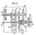
- Fig. 3 With reference to Fig. 3 there is shown a modification of the dual clutch transmission where the additional clutch 29 is co-axial with the countershaft 21.
- Speed ratios are pre-selected by the automatic control in accordance with the usual control parameters and, at the appropriate moment, the automatic control effects a ratio change by disengaging the drive through one clutch as the drive through the other clutch is engaged.
Landscapes
- Engineering & Computer Science (AREA)
- General Engineering & Computer Science (AREA)
- Mechanical Engineering (AREA)
- Structure Of Transmissions (AREA)
Description
- This invention relates to a rotary power transmission of the dual clutch kind for a transverse engined, front wheel drive motor vehicle, by which is meant a transmission having gear trains, each being one of a set providing a series of increasing speed ratios, and two clutches independently operable and providing alternative drive paths through the gear trains between a common input and a common output, the gear trains of alternate speed ratios in the set being driven respectively through one and the other clutch.
- The invention is particularly though not exclusively applicable to drive transmissions for motor vehicles.
- Transmissions of the dual clutch kind are derived from conventional single clutch manual-change transmissions with which they can share many component parts.
- Examples of transmissions of the dual clutch kind are shown in British Patent Specification Nos. 145,827 (Bramley-Moore), 585,716 (Kegresse), 795,260 (David Brown) and 1,225,267 (Bosch). To the best of our knowledge, none of these prior proposals has been commercially adopted.
- For many years it has been customary for vehicle manufacturers to offer each vehicle model with the alternative of a manual-change or, where possible, a fully automatic transmission. As sales of vehicles fitted with automatic transmissions have risen it has become necessary for manufacturers to seek an automatic transmission for every new vehicle model.
- Although most manufacturers use the same basic design of manual-change transmission, many different types of automatic transmissions are in use and most are complicated and carry a heavy cost disadvantage. Moreover each new type and model of automatic transmission requires an expensive test programme to ensure satisfactory strength and functioning, requires the manufacture and stocking of many new parts and may require the training of personnel to service the transmission.
- Conventional automatic transmissions frequently take up more space than their manual-change transmission counterparts. The trend towards front engine-front wheel drive vehicles has meant that, in the smaller vehicle ranges, no automatic transmission option is offered simply because sufficient space to install the transmission is not available.
- Transmissions of the dual clutch kind have not come into use despite having the advantage of simplicity and of component part inter- changability with the equivalent manual-change transmissions.
- Many of the previous proposals for transmissions of the dual clutch kind have the clutches arranged at the same side of the set of gear trains, a single driving member being provided for both clutches in most cases.
- DE-C-965 585 proposes a rail car transmission having fluid couplings located on either side of a set of gear trains. The transmission operates in the same way as a transmission of the dual clutch kind by alternate drive through the fluid couplings. Such a transmission is not suitable for a motor vehicle because of the large space requirement of two torque converters and the slowness of any ratio change. Moreover torque converters would be prohibitively expensive for the transmission disclosed herein.
- According to the present invention in a rotary power transmission of the dual clutch kind, whereby a spring engaged dry plate friction clutch engagable to provide a drive path through the gear train of at least one odd speed ratio is arranged at one side of the set of gear trains adjacent said common input and a fluid-pressure engaged wet friction clutch engagable to provide a drive path through the gear train of at least one even speed ratio is arranged at the other side of the set.
- A major advantage of this arrangement is that a manual-change transmission from which a transmission of the dual clutch kind is adapted, can remain substantially unchanged and the spatial problems of installation are considerably reduced as compared with an arrangement of a dual clutch at one side of the set of gear trains. The external dimensions of a manual-change transmission can remain virtually unchanged except for the provision of an additional clutch which may be located co- axial with the transmission input shaft or with a transmission layshaft.
- A subsidiary advantage of arranging the clutches on either side of the set of gear trains is that the design of control connections to each clutch is eased simply because the clutches are not adjacent.
- Variations are possible in the selection of the type of clutch provided at one side or the other of the set of gear trains, it being possible to suit particular requirements by selecting, for example, a dry plate friction clutch for drive take-up from rest.
- However, the additional clutch is preferably used only for speed ratio changes in the transmission and not for drive take-up from rest. As a result the required capacity of the additional clutch may be much reduced and the consequent benefit of small size together with the aforementioned capability of alternative location within the transmission ensures that space for the clutch can be found in existing installations.
- One clutch may be a dry plate friction clutch and is advantageously the same as that specified for an equivalent manual-change transmission. Preferably this clutch is used for drive take-up from rest only for the gear grain of the lowest forward speed ratio.
- The necessary ancillary controls for the transmission may be situated in the transmission casing or in any convenient space in the installation site.
- The additional clutch may be a fluid-pressure engaged wet friction clutch. Such a clutch can operate in the transmission fluid and so does not require to be sealed from the main transmission casing.
- Adoption of a transmission of the dual clutch kind according to the invention will enable a vehicle manufacturer to take advantage of a number of subsidiary advantages. Interchang- ability of parts with equivalent manual-change transmission will enable the manufacturer to achieve economies of scale, these economies being substantial for relatively expensive components such as gear wheels.
- The additional cost of testing and proving a transmission of the dual clutch kind will be low as compared with the costs for a new design of conventional automatic transmission.
- The manufacturer and vehicle dealer can reduce their spares inventory; servicing of the transmission should be within the capabilities of a skilled mechanic.
- Finally, since it is anticipated that the cost of manufacture and service support of a transmission of the dual clutch kind provided by the invention will be lower than that of a conventional automatic transmission, the cost to the buyer of specifying an automatic transmission option should be much reduced.
- Other features of the invention are included in the following description of two preferred embodiments shown, by way of example only, on the accompanying drawings in which:-
- Fig. 1 illustrates a conventional two shaft manual-change transmission having gear trains in constant mesh;
- Fig. 2 illustrates one embodiment of the invention as applied to the transmission of Fig. 1; and
- Fig. 3 illustrates an alternative embodiment of the invention as applied to the transmission of Fig. 1.
- With reference to Fig. 1 there is shown a conventional four speed gear transmission 11 for interposition in a vehicle drive line between the engine and the driven wheels. The arrangement is particularly suitable for vehicles having transversely mounted engines with front wheel drive, the transmission output being on the same side of the set of gear trains as the input.
- An
input shaft 12 is connectable through adisengagable clutch 13 to a transmissionmain shaft 14. Themain shaft 14 carries fast thereon gear wheels for rotation therewith, respectively forfirst speed ratio 15,second ratio 16,third ratio 17 andfourth ratio 18. - A
countershaft 21 has journalled thereon gear wheels 22-25 for individual rotation, each respectively in mesh with one of the wheels 15-18 of themain shaft 14. -
Synchroniser assemblies countershaft 21 to any one of the gear wheels 22-25. - The
countershaft 21 is the output shaft of the transmission and is connected to the differential gear of the vehicle drive. - Reverse speed ratio may be obtained by any known means, for example, the use of a separate gear train having a lay gear to reverse rotation of the drive. Such an arrangement may be found in many manual-change transmissions.
- The operation of such a gear transmission is well known but for clarity a ratio change from second speed to third speed will be described.
-
Synchroniser assembly 26 is in the rightwards position, as viewed, to connect themain shaft 14 to thecountershaft 21 through secondspeed gear train clutch 13 is engaged and driving torque is transmitted from theinput shaft 12 to thecountershaft 21. The first, third and fourth speed gear trains are driven idly at engine speed by themain shaft 14. - To change speed ratio the
clutch 13 is disengaged, so breaking the driving torque transmitted through the transmission. Synchroniserassembly 26 is moved to disconnect secondspeed gear wheel 23 from the countershaft and thirdspeed gear wheel 24 is connected to thecountershaft 21 by movingsynchroniser assembly 27 leftwards, as viewed. - The ratio change is completed by re- engaging the
clutch 13 to re-establish driving connection between the engine and the vehicle driven wheels. First, second and fourth speed gear trains are now driven idly by the main shaft. - Although the manual-change transmission has been described with the relatively rotatable gear wheels journalled on the
countershaft 21, some or all of the gear trains could have the relatively rotatable gear wheels, under the control of the synchroniser assemblies, supported by the main shaft with the respective meshing gear wheels being fast for rotation with the countershaft. This arrangement would result in some or all of the non-driving gear trains being driven idly at road speed. - The transmission of Fig. 2 and 3 has the position of second and third speed gear trains inter-changed so as to place the "odd" ratios, first and third, and the "even" ratios, second and fourth, in adjacent pairs.
- The transmission main shaft is tubular and divided into two parts so that the "even" gear trains and "odd" gear trains can be separately driven from the
input shaft 12. - Referring to Fig. 2, the "odd" gear trains are driven through the
clutch 13, and the "even" gear trains through anadditional clutch 29 which is itself driven from theinput shaft 12 by ashaft 31 co-axial with and extending through both parts of the tubular main shaft. - It is intended that automatic speed ratio selection would be effected using known automatic transmission control technology as described for example in Torque Converters or Transmissions' by P. M. Heidt and published by Chilton. The transmission would be provided with a selector lever having the usual DRIVE, NUETRAL, REVERSE and PARK positions.
- Operation of the transmission is as follows:-The vehicle engine is running, the selector lever is in NEUTRAL and both
clutches - The vehicle driver engages DRIVE and the transmission automatic control selects first speed by moving
synchroniser assembly 32 to connectgear wheel 22 to thecountershaft 21. As the driver accelerates the engine, the clutch 13 is automatically engaged and driving torque transmitted throughgear wheels - The transmission automatic control can now select second speed by moving
synchroniser assembly 33 to connectgear wheel 23 to thecountershaft 21. Consequently the second ratio drive train ofgear wheels countershaft 21, the drive member of clutch 29 being driven constantly at engine speed by theshaft 31. - The transmission automatic control initiates a ratio change from first speed to second speed in response to the values of the usual control parameters such as throttle opening and road speed.
- The clutch 13 is disengaged as the clutch 29 is engaged and driving torque is progessively transferred from the first ratio gear train to the second ratio gear train so providing a "power on" ratio change. When the change is completed the first ratio drive train is driven idly by the
countershaft 21. - Dependent on the value of the automatic control parameters the
synchroniser assembly 32 will remain with first speed ratio selected or be moved to select third speed ratio by connectinggear wheel 24 to thecountershaft 21. Alternativelysynchroniser assembly 32 may shift to the neutral position until the automatic control indicates an imminent ratio change. - Thus the transmission automatic control is arranged to pre-select the next required speed ratio in sequence, the ratio change being automatically made at the appropriate moment by changing drive from one clutch to the other.
- It is not intended that the additional clutch 29 should be used for drive take up from rest. As a result the required capacity is much reduced and the clutch can be of small size when compared with the
main clutch 13. - With reference to Fig. 3 there is shown a modification of the dual clutch transmission where the additional clutch 29 is co-axial with the
countershaft 21. - The operation of the transmission is as previously described for the embodiment of Fig. 2. Speed ratios are pre-selected by the automatic control in accordance with the usual control parameters and, at the appropriate moment, the automatic control effects a ratio change by disengaging the drive through one clutch as the drive through the other clutch is engaged.
- Although the invention has been described with reference to a constant mesh gear arrangement, it is equally adaptable to other gear arrangements such as, for example, those utilising sliding gears or sliding dogs.
Claims (3)
Applications Claiming Priority (2)
| Application Number | Priority Date | Filing Date | Title |
|---|---|---|---|
| GB7940750 | 1979-11-26 | ||
| GB7940750 | 1979-11-26 |
Publications (3)
| Publication Number | Publication Date |
|---|---|
| EP0029711A2 EP0029711A2 (en) | 1981-06-03 |
| EP0029711A3 EP0029711A3 (en) | 1981-10-14 |
| EP0029711B1 true EP0029711B1 (en) | 1983-11-23 |
Family
ID=10509413
Family Applications (1)
| Application Number | Title | Priority Date | Filing Date |
|---|---|---|---|
| EP19800304160 Expired EP0029711B1 (en) | 1979-11-26 | 1980-11-20 | Rotary power transmission |
Country Status (7)
| Country | Link |
|---|---|
| EP (1) | EP0029711B1 (en) |
| JP (1) | JPS5694050A (en) |
| AU (1) | AU6430980A (en) |
| BR (1) | BR8007707A (en) |
| DE (1) | DE3065725D1 (en) |
| ES (1) | ES8201900A1 (en) |
| GB (1) | GB2064028A (en) |
Families Citing this family (39)
| Publication number | Priority date | Publication date | Assignee | Title |
|---|---|---|---|---|
| GB2070158B (en) * | 1980-02-18 | 1984-04-04 | Automotive Prod Co Ltd | Rotary transmission |
| EP0034412A3 (en) * | 1980-02-18 | 1981-12-16 | Automotive Products Public Limited Company | Rotary power transmission |
| AU552791B2 (en) * | 1981-09-19 | 1986-06-19 | Automotive Products Plc | Transmission |
| JPS58166157A (en) * | 1982-03-29 | 1983-10-01 | Mazda Motor Corp | Method and device for controlling speed change of complex clutch type gear transmission |
| US4517859A (en) * | 1982-01-05 | 1985-05-21 | Mazda Motor Corporation | Shift up clutch control in a multiple clutch type gear transmission for automobile |
| JPS58118355A (en) * | 1982-01-08 | 1983-07-14 | Nissan Motor Co Ltd | Transmission for vehicle |
| EP0088486A3 (en) * | 1982-02-05 | 1985-05-22 | Automotive Products Public Limited Company | Rotary transmission |
| JPS58146749A (en) * | 1982-02-22 | 1983-09-01 | Mazda Motor Corp | Double lock detecting device of compound clutch type multistage speed change gear |
| JPS58146748A (en) * | 1982-02-22 | 1983-09-01 | Mazda Motor Corp | Speed change control device of compound clutch type multistage speed change gear |
| US4576063A (en) * | 1982-02-27 | 1986-03-18 | Toyota Jidosha Kabushiki Kaisha | Transmission mechanism with parallel transmission systems including one way clutches, one being lockable |
| JPS58149449A (en) * | 1982-03-02 | 1983-09-05 | Toyota Motor Corp | Speed change controlling method of vehicular automatic transmission |
| JPS58149448A (en) * | 1982-02-27 | 1983-09-05 | Toyota Motor Corp | Speed change controlling method of vehicular automatic transmission |
| JPS5962751A (en) * | 1982-09-29 | 1984-04-10 | Mazda Motor Corp | Complex clutch type speed change gear |
| GB2136895B (en) * | 1983-03-24 | 1986-07-16 | Automotive Products Plc | Automatic transmission control |
| US4513631A (en) * | 1983-06-16 | 1985-04-30 | General Motors Corporation | Dual input clutch transmission |
| GB8411896D0 (en) * | 1984-05-10 | 1984-06-13 | Automotive Prod Plc | Transmission |
| GB2159216B (en) * | 1984-05-25 | 1988-08-10 | Automotive Products Plc | Transmission control system |
| JPS60191754U (en) * | 1984-05-29 | 1985-12-19 | マツダ株式会社 | vehicle gear transmission |
| FR2566718B1 (en) * | 1984-06-29 | 1989-08-18 | Peugeot | TRANSMISSION DEVICE BETWEEN A MOTOR SHAFT AND TWO RECEIVING SHAFTS, PARTICULARLY FOR DRIVING A GEARBOX |
| GB9602731D0 (en) | 1996-02-10 | 1996-04-10 | Ap Kongsberg Holdings Ltd | Transmission control systems |
| FR2801010B1 (en) * | 1999-11-15 | 2002-02-01 | Peugeot Citroen Automobiles Sa | TORQUE TRANSMISSION AND CONVERSION DEVICE USING A GEARBOX AND TWO CLUTCHES |
| US6364809B1 (en) * | 2000-05-18 | 2002-04-02 | Daimlerchrysler Corporation | Clutch control system for upshift of an electro-mechanical automatic transmission |
| GB0310482D0 (en) | 2003-05-07 | 2003-06-11 | Zero Shift Ltd | Shaft engagement mechanism |
| BRPI0412454B1 (en) | 2003-07-08 | 2017-02-14 | Zeroshift Ltd | transmission system |
| GB0321824D0 (en) | 2003-09-18 | 2003-10-15 | Zeroshift Ltd | Electromagnetic engagement mechanism |
| JP4602026B2 (en) | 2004-08-10 | 2010-12-22 | 本田技研工業株式会社 | Engine equipped with an automatic transmission for vehicles |
| GB0510129D0 (en) * | 2005-05-18 | 2005-06-22 | Zeroshift Ltd | Sequential hub layout |
| US7601095B2 (en) * | 2005-07-20 | 2009-10-13 | Kanzaki Kokyukoki Mfg. Co., Ltd. | Vehicle |
| US8050827B2 (en) | 2005-07-20 | 2011-11-01 | Kanzaki Kokyukoki Mfg. Co., Ltd. | Vehicle transmission system |
| US7665376B2 (en) * | 2006-03-31 | 2010-02-23 | Magna Powertrain Usa, Inc. | Dual clutch powershift transmission |
| JP5264415B2 (en) * | 2008-10-30 | 2013-08-14 | ヤマハ発動機株式会社 | Twin-clutch transmission, vehicle equipped with the same, and motorcycle |
| DE102009053913A1 (en) * | 2009-11-19 | 2011-05-26 | GM Global Technology Operations LLC, ( n. d. Ges. d. Staates Delaware ), Detroit | Two-shaft transmission of a motor vehicle |
| CN101852289A (en) * | 2010-06-13 | 2010-10-06 | 程秀生 | Heavy-duty and rear-drive automobile wet-type double-clutch automatic speed-change power transmission device |
| GB201109100D0 (en) | 2011-05-27 | 2011-07-13 | Zeroshift Ltd | Transmission system |
| RU2595203C1 (en) * | 2015-07-06 | 2016-08-20 | Федеральное государственное бюджетное образовательное учреждение высшего образования "Тюменский индустриальный университет" (ТИУ) | Two-shaft misaligned six-speed gearbox with two clutches |
| DE102017204125A1 (en) * | 2017-03-13 | 2018-09-13 | Zf Friedrichshafen Ag | Dual clutch transmission assembly and motor vehicle |
| DE102017204127A1 (en) | 2017-03-13 | 2018-09-13 | Zf Friedrichshafen Ag | Dual clutch transmission assembly and motor vehicle |
| DE102017204126A1 (en) * | 2017-03-13 | 2018-09-13 | Zf Friedrichshafen Ag | Dual clutch transmission assembly and motor vehicle |
| CN110513448A (en) * | 2019-08-27 | 2019-11-29 | 宁波上中下自动变速器有限公司 | A kind of hybrid gearbox and vehicle |
Family Cites Families (10)
| Publication number | Priority date | Publication date | Assignee | Title |
|---|---|---|---|---|
| GB795260A (en) * | 1955-09-29 | 1958-05-21 | Brown David & Sons Ltd | An improvement in or relating to variable-speed gearboxes |
| GB808546A (en) * | 1956-01-09 | 1959-02-04 | Rech S Pour Engins Mecaniques | Improvements in or relating to gear boxes |
| FR1207451A (en) * | 1957-06-26 | 1960-02-17 | Daimler Benz Ag | Coupling capable of being disengaged, in particular for motor vehicle gearshifting and operating mechanism with this coupling |
| FR1230353A (en) * | 1959-07-20 | 1960-09-15 | Further training in gearboxes, in particular for public works machinery | |
| DE1286856B (en) * | 1962-07-06 | 1969-01-09 | Deckel Dipl Ing Friedrich Wilh | Gear change transmission |
| FR1469727A (en) * | 1966-02-21 | 1967-02-17 | Bosch Gmbh Robert | Stationary case gearbox |
| GB1225265A (en) * | 1968-02-28 | 1971-03-17 | ||
| DE2029572A1 (en) * | 1970-06-16 | 1971-12-23 | Klockner Humboldt Deutz AG, 5000 Köln | Engine that can be switched under load |
| GB1349936A (en) * | 1970-09-23 | 1974-04-10 | Brown Gear Ind | Change-speed gear-boxes |
| US3991634A (en) * | 1974-12-19 | 1976-11-16 | Allis-Chalmers Corporation | Countershaft auxiliary transmission |
-
1980
- 1980-11-12 AU AU64309/80A patent/AU6430980A/en not_active Abandoned
- 1980-11-20 EP EP19800304160 patent/EP0029711B1/en not_active Expired
- 1980-11-20 GB GB8037290A patent/GB2064028A/en not_active Withdrawn
- 1980-11-20 DE DE8080304160T patent/DE3065725D1/en not_active Expired
- 1980-11-25 ES ES497117A patent/ES8201900A1/en not_active Expired
- 1980-11-25 JP JP16577980A patent/JPS5694050A/en active Pending
- 1980-11-26 BR BR8007707A patent/BR8007707A/en unknown
Also Published As
| Publication number | Publication date |
|---|---|
| JPS5694050A (en) | 1981-07-30 |
| ES497117A0 (en) | 1982-01-16 |
| EP0029711A3 (en) | 1981-10-14 |
| GB2064028A (en) | 1981-06-10 |
| ES8201900A1 (en) | 1982-01-16 |
| AU6430980A (en) | 1981-06-04 |
| DE3065725D1 (en) | 1983-12-29 |
| BR8007707A (en) | 1981-06-09 |
| EP0029711A2 (en) | 1981-06-03 |
Similar Documents
| Publication | Publication Date | Title |
|---|---|---|
| EP0029711A2 (en) | Rotary power transmission | |
| US4544057A (en) | Rotary transmission | |
| US6286381B1 (en) | Gear preselect system for an electro-mechanical automatic transmission having dual input shafts | |
| CN100538126C (en) | Sensor system and method for controlling an automated dual clutch transmission | |
| EP1586797B1 (en) | Parking mechanism for transmission | |
| US6186029B1 (en) | Dual input transmission | |
| US8156837B2 (en) | Multiple-ratio transmission with concentric offset shift forks | |
| US7587957B2 (en) | Multiple-ratio dual clutch vehicle transmission | |
| EP0046373A1 (en) | Rotary transmission | |
| EP0061845A2 (en) | Rotary transmission | |
| JPH06221347A (en) | Counter-shaft automatic transmission | |
| GB2069635A (en) | Rotary transmission | |
| JPH09511314A (en) | Automotive transmission | |
| US6648795B2 (en) | Transmission system for vehicle | |
| US6406400B1 (en) | Integrated vehicle manual transmission and clutch with planetary gear arrangement | |
| CN104089003B (en) | A kind of double-clutch automatic gearbox limp-home controlling method | |
| EP0034411A2 (en) | Rotary transmission | |
| EP0061903A2 (en) | Rotary transmission | |
| US6427551B2 (en) | Transmission for vehicle | |
| EP0034412A2 (en) | Rotary power transmission | |
| JP3989811B2 (en) | Transmission with auxiliary transmission mechanism | |
| EP0293248B1 (en) | Automotive transmission | |
| EP0042677A1 (en) | Rotary transmission | |
| GB2078318A (en) | Rotary change-speed transmission | |
| EP0092964A1 (en) | Change speed transmission |
Legal Events
| Date | Code | Title | Description |
|---|---|---|---|
| PUAI | Public reference made under article 153(3) epc to a published international application that has entered the european phase |
Free format text: ORIGINAL CODE: 0009012 |
|
| AK | Designated contracting states |
Designated state(s): DE FR GB IT |
|
| PUAL | Search report despatched |
Free format text: ORIGINAL CODE: 0009013 |
|
| AK | Designated contracting states |
Designated state(s): DE FR GB IT |
|
| 17P | Request for examination filed |
Effective date: 19810813 |
|
| RAP1 | Party data changed (applicant data changed or rights of an application transferred) |
Owner name: AUTOMOTIVE PRODUCTS PUBLIC LIMITED COMPANY |
|
| RBV | Designated contracting states (corrected) |
Designated state(s): DE FR GB IT |
|
| ITF | It: translation for a ep patent filed | ||
| GRAA | (expected) grant |
Free format text: ORIGINAL CODE: 0009210 |
|
| AK | Designated contracting states |
Designated state(s): DE FR GB IT |
|
| REF | Corresponds to: |
Ref document number: 3065725 Country of ref document: DE Date of ref document: 19831229 |
|
| ET | Fr: translation filed | ||
| PLBE | No opposition filed within time limit |
Free format text: ORIGINAL CODE: 0009261 |
|
| STAA | Information on the status of an ep patent application or granted ep patent |
Free format text: STATUS: NO OPPOSITION FILED WITHIN TIME LIMIT |
|
| PGFP | Annual fee paid to national office [announced via postgrant information from national office to epo] |
Ref country code: DE Payment date: 19841023 Year of fee payment: 5 |
|
| 26N | No opposition filed | ||
| GBPC | Gb: european patent ceased through non-payment of renewal fee | ||
| PG25 | Lapsed in a contracting state [announced via postgrant information from national office to epo] |
Ref country code: DE Effective date: 19880802 |
|
| PG25 | Lapsed in a contracting state [announced via postgrant information from national office to epo] |
Ref country code: GB Effective date: 19881118 |
|
| PGFP | Annual fee paid to national office [announced via postgrant information from national office to epo] |
Ref country code: FR Payment date: 19891008 Year of fee payment: 10 |
|
| PG25 | Lapsed in a contracting state [announced via postgrant information from national office to epo] |
Ref country code: FR Effective date: 19910731 |
|
| REG | Reference to a national code |
Ref country code: FR Ref legal event code: ST |