EP0029506B1 - Einrichtung zur Reduzierung des Auspuff- bzw. Abgaslärmes - Google Patents
Einrichtung zur Reduzierung des Auspuff- bzw. Abgaslärmes Download PDFInfo
- Publication number
- EP0029506B1 EP0029506B1 EP80106431A EP80106431A EP0029506B1 EP 0029506 B1 EP0029506 B1 EP 0029506B1 EP 80106431 A EP80106431 A EP 80106431A EP 80106431 A EP80106431 A EP 80106431A EP 0029506 B1 EP0029506 B1 EP 0029506B1
- Authority
- EP
- European Patent Office
- Prior art keywords
- silators
- waste gas
- impedance
- exhaust
- noise
- Prior art date
- Legal status (The legal status is an assumption and is not a legal conclusion. Google has not performed a legal analysis and makes no representation as to the accuracy of the status listed.)
- Expired
Links
Images
Classifications
-
- F—MECHANICAL ENGINEERING; LIGHTING; HEATING; WEAPONS; BLASTING
- F01—MACHINES OR ENGINES IN GENERAL; ENGINE PLANTS IN GENERAL; STEAM ENGINES
- F01N—GAS-FLOW SILENCERS OR EXHAUST APPARATUS FOR MACHINES OR ENGINES IN GENERAL; GAS-FLOW SILENCERS OR EXHAUST APPARATUS FOR INTERNAL-COMBUSTION ENGINES
- F01N1/00—Silencing apparatus characterised by method of silencing
- F01N1/16—Silencing apparatus characterised by method of silencing by using movable parts
- F01N1/22—Silencing apparatus characterised by method of silencing by using movable parts the parts being resilient walls
-
- F—MECHANICAL ENGINEERING; LIGHTING; HEATING; WEAPONS; BLASTING
- F01—MACHINES OR ENGINES IN GENERAL; ENGINE PLANTS IN GENERAL; STEAM ENGINES
- F01N—GAS-FLOW SILENCERS OR EXHAUST APPARATUS FOR MACHINES OR ENGINES IN GENERAL; GAS-FLOW SILENCERS OR EXHAUST APPARATUS FOR INTERNAL-COMBUSTION ENGINES
- F01N1/00—Silencing apparatus characterised by method of silencing
- F01N1/02—Silencing apparatus characterised by method of silencing by using resonance
-
- F—MECHANICAL ENGINEERING; LIGHTING; HEATING; WEAPONS; BLASTING
- F01—MACHINES OR ENGINES IN GENERAL; ENGINE PLANTS IN GENERAL; STEAM ENGINES
- F01N—GAS-FLOW SILENCERS OR EXHAUST APPARATUS FOR MACHINES OR ENGINES IN GENERAL; GAS-FLOW SILENCERS OR EXHAUST APPARATUS FOR INTERNAL-COMBUSTION ENGINES
- F01N2490/00—Structure, disposition or shape of gas-chambers
- F01N2490/14—Dead or resonance chambers connected to gas flow tube by relatively short side-tubes
Definitions
- the invention relates to a device for reducing the exhaust or exhaust noise of hot and aggressive exhaust gases from internal combustion engines or thermodynamic systems by means of silators tuned to different frequencies.
- silencers have been proposed in various forms to dampen the noise of exhaust or exhaust systems, but they are all based on the same relatively few basic principles, which are primarily absorption systems on open-pore materials, insulation by means of coordinated resonance volumes and impedance jumps. All of these known devices require relatively large designs and also these silencers are subject to very strong corrosion phenomena and the frequently occurring implementation of the absorption materials.
- silators volume-changing resonators
- the invention has for its object to provide a device of the type mentioned, which allows exhaust or exhaust systems to be reduced in volume, but to increase the muffler effect.
- silators - Due to the proposed resonating resonators - which are referred to as silators - which are integrated with the exhaust gas channel, an impedance dip occurs in the region of their resonance frequency, which causes reflection. If several silators tuned to different frequencies are now arranged, broadband sound insulation is achieved in a simple manner. If the silators are now dampened, as provided by a preferred feature of the invention, they also absorb sound due to their resistance, and if the silator walls are provided with an anti-drumming coating, additional sound absorption takes place. In order to reduce the vibrating mass, it is advantageous if only the edge parts are provided with the covering. Of course, it is of course also possible to use the known method of using counter leaflets.
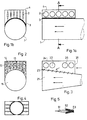
- FIG. 1 and 1b show a schematic representation of sections through an exhaust or exhaust duct 1, which is provided with the silators 2 according to the proposal according to the invention. These are lenticular vacuum spaces made of sheet metal. Such silators are described in detail in DE-OS 2632290. Such elements have pronounced resonances, the impedances of which are below that of the air. Overall, this results in an impedance jump with an effective insulation effect. In order to make them broadband, several silators tuned to different frequencies are used. These are housed in a protective housing 4 and shielded against the exhaust duct 1 with metal wool 3. Instead of metal wool, other materials or perforated sheet metal can also be used.
- FIG. 1 shows an analog design, consisting of exhaust duct 11, silators 12 and protective housing 14. Between the silators 12 there is a sound-permeable material 13, e.g. B. metal wool. The mode of operation is also the same as that described in FIG. 1.
- FIG 3 again shows a longitudinal section through an exhaust duct 21 provided with a muffler, which in this case is divergent at its gas outlet in the direction of flow.
- the silators 22 and 26 are seated, the former being dimensioned such that their impedance is smaller than the air impedance and the latter 26 are damped and approximately matched to the air impedance. This ensures optimal sound absorption.
- the silators 22 and 26 are accommodated in a protective housing 24 which has an opening 25 on one side.
- a perforated plate 23 is located between the exhaust duct 21 and the silators 22 and 26.
- Fig. 4 shows an embodiment according to the invention, which is substantially analogous to that shown in Figs. 1a and 1.
- Silators arranged on opposite sides. These are again in a protective housing and are separated from the exhaust duct by a sound-permeable material.
- FIG. 1 shows an exemplary embodiment with damped silators 51. These have, preferably in the region of the exhaust gas jet, a damping coating or anti-drumming agent 52 which is covered by a contour plate 53. In order not to increase the resonating mass of the silators 51, this assignment is preferably located in the edge region of the silators 51. Due to this damping of the silators, they also absorb the sound due to their resistance.
Landscapes
- Engineering & Computer Science (AREA)
- Chemical & Material Sciences (AREA)
- Combustion & Propulsion (AREA)
- Mechanical Engineering (AREA)
- General Engineering & Computer Science (AREA)
- Exhaust Silencers (AREA)
Applications Claiming Priority (2)
| Application Number | Priority Date | Filing Date | Title |
|---|---|---|---|
| DE2947256A DE2947256C2 (de) | 1979-11-23 | 1979-11-23 | Einrichtung zur Reduzierung des Auspuff- bzw. Abgaslärmes |
| DE2947256 | 1979-11-23 |
Publications (2)
| Publication Number | Publication Date |
|---|---|
| EP0029506A1 EP0029506A1 (de) | 1981-06-03 |
| EP0029506B1 true EP0029506B1 (de) | 1983-09-07 |
Family
ID=6086711
Family Applications (1)
| Application Number | Title | Priority Date | Filing Date |
|---|---|---|---|
| EP80106431A Expired EP0029506B1 (de) | 1979-11-23 | 1980-10-22 | Einrichtung zur Reduzierung des Auspuff- bzw. Abgaslärmes |
Country Status (4)
| Country | Link |
|---|---|
| US (1) | US4325458A (cg-RX-API-DMAC10.html) |
| EP (1) | EP0029506B1 (cg-RX-API-DMAC10.html) |
| JP (1) | JPS5685512A (cg-RX-API-DMAC10.html) |
| DE (1) | DE2947256C2 (cg-RX-API-DMAC10.html) |
Families Citing this family (4)
| Publication number | Priority date | Publication date | Assignee | Title |
|---|---|---|---|---|
| US5129793A (en) * | 1990-10-24 | 1992-07-14 | Copeland Corporation | Suction muffler |
| US5267321A (en) * | 1991-11-19 | 1993-11-30 | Edwin Langberg | Active sound absorber |
| US5341654A (en) * | 1993-04-16 | 1994-08-30 | Copeland Corporation | Suction gas conduit |
| DE10102040A1 (de) * | 2001-01-18 | 2002-07-25 | Mahle Filtersysteme Gmbh | Schalldämpfer |
Family Cites Families (13)
| Publication number | Priority date | Publication date | Assignee | Title |
|---|---|---|---|---|
| US2904125A (en) * | 1953-05-08 | 1959-09-15 | Emhart Mfg Co | Straight through silencer |
| CH436759A (de) * | 1964-07-28 | 1967-05-31 | Airtherm Consulting Ag | Vorrichtung zur Schalldämpfung in von Gas durchströmten Kanälen mittels eines Membranschalldämpfers |
| JPS4937651U (cg-RX-API-DMAC10.html) * | 1972-07-11 | 1974-04-03 | ||
| DE7330817U (de) * | 1973-07-13 | 1975-06-05 | Bbc Ag Brown Boveri & Cie | Absorptionsschalldämpfer |
| US3920095A (en) * | 1974-02-01 | 1975-11-18 | Brunswick Corp | Free flow sound attenuating device and method of using |
| DE2433795C3 (de) * | 1974-07-13 | 1980-12-18 | Oskar Dipl.-Ing. Dr.Rer.Nat. 8000 Muenchen Bschorr | Zwei- oder mehrschalige Hohlwand zur Abschirmung von Störschallquellen |
| CH581261A5 (en) * | 1974-08-15 | 1976-10-29 | Bernard Robert | IC engine exhaust gas silencer - with gases passing through two concentric insulated chambers and entering Venturi at throat |
| FR2288858A1 (fr) * | 1974-10-24 | 1976-05-21 | Plessy Fernand | Silencieux pour moteurs |
| FR2321590A2 (fr) * | 1975-08-22 | 1977-03-18 | Plessy Fernand | Perfectionnements aux silencieux pour moteur |
| US4104426A (en) * | 1975-11-28 | 1978-08-01 | Mcdonnell Douglas Corporation | Production of muffler material |
| DE2632290C3 (de) * | 1976-07-17 | 1980-02-14 | Messerschmitt-Boelkow-Blohm Gmbh, 8000 Muenchen | Schallreduktion durch mitschwingende Resonatoren |
| DE2834823C2 (de) * | 1978-08-09 | 1980-07-17 | Messerschmitt-Boelkow-Blohm Gmbh, 8000 Muenchen | Volumenändernde Resonatoren nach dem Tellerfeder-Prinzip |
| US4228869A (en) * | 1976-07-17 | 1980-10-21 | Messerschmitt-Bolkow-Blohm Gmbh | Variable volume resonators using the Belleville spring principle |
-
1979
- 1979-11-23 DE DE2947256A patent/DE2947256C2/de not_active Expired
-
1980
- 1980-10-22 EP EP80106431A patent/EP0029506B1/de not_active Expired
- 1980-11-14 US US06/207,088 patent/US4325458A/en not_active Expired - Lifetime
- 1980-11-22 JP JP16405280A patent/JPS5685512A/ja active Granted
Also Published As
| Publication number | Publication date |
|---|---|
| EP0029506A1 (de) | 1981-06-03 |
| US4325458A (en) | 1982-04-20 |
| DE2947256A1 (de) | 1981-05-27 |
| DE2947256C2 (de) | 1984-09-13 |
| JPH0152563B2 (cg-RX-API-DMAC10.html) | 1989-11-09 |
| JPS5685512A (en) | 1981-07-11 |
Similar Documents
| Publication | Publication Date | Title |
|---|---|---|
| DE60001089T2 (de) | Veränderbarer Resonator | |
| DE102011108871A1 (de) | Resonator | |
| DE10102040A1 (de) | Schalldämpfer | |
| DE3317273C2 (cg-RX-API-DMAC10.html) | ||
| DE69723870T2 (de) | Vorrichtung und verfahren zur schalldämpfung in einem transportsystem für gasförmige stoffe und anwendung einer solchen vorrichtung in einem abgassystem eines schiffes | |
| DE19743446C2 (de) | Abgasanlage für eine Brennkraftmaschine | |
| DE2908506C2 (de) | Schalldämpfer für Verbrennungskraftmaschinen | |
| EP0713046B1 (de) | Vorrichtung zur Schalldämmung in Rohrleitungen | |
| DE2545364C3 (cg-RX-API-DMAC10.html) | ||
| DE19703414A1 (de) | Geräuschdämpfer | |
| EP0029506B1 (de) | Einrichtung zur Reduzierung des Auspuff- bzw. Abgaslärmes | |
| DE3034575C2 (cg-RX-API-DMAC10.html) | ||
| DE3811181C2 (cg-RX-API-DMAC10.html) | ||
| DE69607496T2 (de) | Schallgedämpfte Verbrennungsanlage und Dämpfer für eine solche Anlage | |
| DE2924153C2 (de) | Zweitluft-Zuführeinrichtung zum Zuführen von Zweitluft in die Abgasanlage einer mit einem Luftfilter versehenen Brennkraftmaschine | |
| EP0802308B1 (de) | Schalldämpfer | |
| DE7307335U (de) | Abgasschalldaempfer fuer zweitakt- motore | |
| DE1953304A1 (de) | Abgasfilter | |
| EP0708881B1 (de) | Schalldämpfer für verbrennungsmotor, insbesondere einzylinder-dieselmotor | |
| DE2527111A1 (de) | Schalldaempfer | |
| DE634222C (de) | Schalldaempfer | |
| DE202011001554U1 (de) | Auspuffanordnung zur Verwendung mit einem Verbrennungsmotor | |
| DE663909C (de) | Schalldaempfer fuer Brennkraftmaschinen unter Benutzung akustischer Filter | |
| DE8709527U1 (de) | Abgasschalldämpfer | |
| DE554601C (de) | Schalldaempfer fuer Brennkraftmaschinen |
Legal Events
| Date | Code | Title | Description |
|---|---|---|---|
| PUAI | Public reference made under article 153(3) epc to a published international application that has entered the european phase |
Free format text: ORIGINAL CODE: 0009012 |
|
| AK | Designated contracting states |
Designated state(s): FR GB IT |
|
| 17P | Request for examination filed |
Effective date: 19810615 |
|
| ITF | It: translation for a ep patent filed | ||
| GRAA | (expected) grant |
Free format text: ORIGINAL CODE: 0009210 |
|
| AK | Designated contracting states |
Designated state(s): FR GB IT |
|
| ET | Fr: translation filed | ||
| PLBE | No opposition filed within time limit |
Free format text: ORIGINAL CODE: 0009261 |
|
| STAA | Information on the status of an ep patent application or granted ep patent |
Free format text: STATUS: NO OPPOSITION FILED WITHIN TIME LIMIT |
|
| 26N | No opposition filed | ||
| PGFP | Annual fee paid to national office [announced via postgrant information from national office to epo] |
Ref country code: GB Payment date: 19890930 Year of fee payment: 10 |
|
| PGFP | Annual fee paid to national office [announced via postgrant information from national office to epo] |
Ref country code: FR Payment date: 19891010 Year of fee payment: 10 |
|
| ITTA | It: last paid annual fee | ||
| PG25 | Lapsed in a contracting state [announced via postgrant information from national office to epo] |
Ref country code: GB Effective date: 19901022 |
|
| GBPC | Gb: european patent ceased through non-payment of renewal fee | ||
| PG25 | Lapsed in a contracting state [announced via postgrant information from national office to epo] |
Ref country code: FR Effective date: 19910628 |
|
| REG | Reference to a national code |
Ref country code: FR Ref legal event code: ST |