EP0028976B1 - Procédé de réalisation d'une jonction entre deux fils métalliques de dimension très réduite - Google Patents
Procédé de réalisation d'une jonction entre deux fils métalliques de dimension très réduite Download PDFInfo
- Publication number
- EP0028976B1 EP0028976B1 EP80401582A EP80401582A EP0028976B1 EP 0028976 B1 EP0028976 B1 EP 0028976B1 EP 80401582 A EP80401582 A EP 80401582A EP 80401582 A EP80401582 A EP 80401582A EP 0028976 B1 EP0028976 B1 EP 0028976B1
- Authority
- EP
- European Patent Office
- Prior art keywords
- wire
- process according
- tube
- weld
- junction
- Prior art date
- Legal status (The legal status is an assumption and is not a legal conclusion. Google has not performed a legal analysis and makes no representation as to the accuracy of the status listed.)
- Expired
Links
- 238000000034 method Methods 0.000 title claims description 25
- 229910052751 metal Inorganic materials 0.000 title claims description 18
- 239000002184 metal Substances 0.000 title claims description 18
- BASFCYQUMIYNBI-UHFFFAOYSA-N platinum Chemical compound [Pt] BASFCYQUMIYNBI-UHFFFAOYSA-N 0.000 claims description 19
- 229910001179 chromel Inorganic materials 0.000 claims description 16
- 229910000809 Alumel Inorganic materials 0.000 claims description 14
- 229910001220 stainless steel Inorganic materials 0.000 claims description 11
- 239000010935 stainless steel Substances 0.000 claims description 10
- ZOKXTWBITQBERF-UHFFFAOYSA-N Molybdenum Chemical compound [Mo] ZOKXTWBITQBERF-UHFFFAOYSA-N 0.000 claims description 9
- 229910052750 molybdenum Inorganic materials 0.000 claims description 9
- 239000011733 molybdenum Substances 0.000 claims description 9
- 239000000463 material Substances 0.000 claims description 8
- 229910052697 platinum Inorganic materials 0.000 claims description 8
- 238000003466 welding Methods 0.000 claims description 7
- 229910000829 Nisil Inorganic materials 0.000 claims description 4
- 125000006850 spacer group Chemical group 0.000 claims description 4
- 230000000694 effects Effects 0.000 claims description 3
- 238000004519 manufacturing process Methods 0.000 claims description 3
- 150000002739 metals Chemical class 0.000 claims description 3
- 229910000768 nicrosil Inorganic materials 0.000 claims description 3
- 229910010293 ceramic material Inorganic materials 0.000 claims description 2
- 239000011810 insulating material Substances 0.000 claims 1
- 229910052703 rhodium Inorganic materials 0.000 claims 1
- 239000010948 rhodium Substances 0.000 claims 1
- MHOVAHRLVXNVSD-UHFFFAOYSA-N rhodium atom Chemical compound [Rh] MHOVAHRLVXNVSD-UHFFFAOYSA-N 0.000 claims 1
- 238000005491 wire drawing Methods 0.000 claims 1
- 230000004907 flux Effects 0.000 description 12
- 238000005259 measurement Methods 0.000 description 8
- 238000009792 diffusion process Methods 0.000 description 6
- PNEYBMLMFCGWSK-UHFFFAOYSA-N aluminium oxide Inorganic materials [O-2].[O-2].[O-2].[Al+3].[Al+3] PNEYBMLMFCGWSK-UHFFFAOYSA-N 0.000 description 5
- 238000010438 heat treatment Methods 0.000 description 5
- 239000000523 sample Substances 0.000 description 4
- CPLXHLVBOLITMK-UHFFFAOYSA-N Magnesium oxide Chemical compound [Mg]=O CPLXHLVBOLITMK-UHFFFAOYSA-N 0.000 description 2
- 239000004020 conductor Substances 0.000 description 2
- 238000009826 distribution Methods 0.000 description 2
- 239000012212 insulator Substances 0.000 description 2
- LIXXICXIKUPJBX-UHFFFAOYSA-N [Pt].[Rh].[Pt] Chemical compound [Pt].[Rh].[Pt] LIXXICXIKUPJBX-UHFFFAOYSA-N 0.000 description 1
- 239000011149 active material Substances 0.000 description 1
- 229910052782 aluminium Inorganic materials 0.000 description 1
- XAGFODPZIPBFFR-UHFFFAOYSA-N aluminium Chemical compound [Al] XAGFODPZIPBFFR-UHFFFAOYSA-N 0.000 description 1
- 238000009529 body temperature measurement Methods 0.000 description 1
- 239000000919 ceramic Substances 0.000 description 1
- 239000012671 ceramic insulating material Substances 0.000 description 1
- 229910052804 chromium Inorganic materials 0.000 description 1
- 238000007796 conventional method Methods 0.000 description 1
- 238000010586 diagram Methods 0.000 description 1
- 238000010292 electrical insulation Methods 0.000 description 1
- 238000011156 evaluation Methods 0.000 description 1
- 230000003100 immobilizing effect Effects 0.000 description 1
- 238000005304 joining Methods 0.000 description 1
- 230000004807 localization Effects 0.000 description 1
- 239000000395 magnesium oxide Substances 0.000 description 1
- 239000000203 mixture Substances 0.000 description 1
- PXXKQOPKNFECSZ-UHFFFAOYSA-N platinum rhodium Chemical compound [Rh].[Pt] PXXKQOPKNFECSZ-UHFFFAOYSA-N 0.000 description 1
- 230000005855 radiation Effects 0.000 description 1
- 230000009466 transformation Effects 0.000 description 1
- XLYOFNOQVPJJNP-UHFFFAOYSA-N water Substances O XLYOFNOQVPJJNP-UHFFFAOYSA-N 0.000 description 1
Images
Classifications
-
- G—PHYSICS
- G01—MEASURING; TESTING
- G01K—MEASURING TEMPERATURE; MEASURING QUANTITY OF HEAT; THERMALLY-SENSITIVE ELEMENTS NOT OTHERWISE PROVIDED FOR
- G01K7/00—Measuring temperature based on the use of electric or magnetic elements directly sensitive to heat ; Power supply therefor, e.g. using thermoelectric elements
- G01K7/02—Measuring temperature based on the use of electric or magnetic elements directly sensitive to heat ; Power supply therefor, e.g. using thermoelectric elements using thermoelectric elements, e.g. thermocouples
-
- G—PHYSICS
- G01—MEASURING; TESTING
- G01T—MEASUREMENT OF NUCLEAR OR X-RADIATION
- G01T3/00—Measuring neutron radiation
- G01T3/006—Measuring neutron radiation using self-powered detectors (for neutrons as well as for Y- or X-rays), e.g. using Compton-effect (Compton diodes) or photo-emission or a (n,B) nuclear reaction
Definitions
- the present invention relates to the production of a junction between two metal wires of very reduced size in order to obtain measuring devices from this junction.
- the present invention seeks to obtain a junction between a wire of a first metal and a wire of a second metal corresponding to a very reduced junction length between these two wires, for example, less than 10 microns.
- thermocouples distributed along this bar which occupies substantially the entire height of the reactor core. It is necessary that these bars have a reduced diameter and consequently, it is therefore a fortiori necessary that these differential thermocouples also have a very reduced diameter. More specifically, it is very desirable that the outside diameter of the thermocouple, including its electrical insulation elements, be of the order of 1 to 0.5 mm.
- differential thermocouples If the principle of differential thermocouples is well known and their realization in general also well known, it turns out to be much more difficult to produce differential thermocouples whose diameter is compatible with the requirements required to house these thermocouples in a stainless steel bar for temperature measurement due to y radiation in the core of a nuclear reactor.
- the weld 5 in its final state has a length of 140 mm. If we are satisfied with an outside diameter of 1 mm, the weld is still 35 mm long. However, such weld lengths are incompatible with a precise measurement of the temperature rise y due to the imprecision of the location of the weld ensuring the measurement.
- a known neutron flux measurement device consists of an active platinum wire which behaves like a ⁇ collector.
- This platinum wire is connected, on the one hand by welding to a conductive wire, for example made of stainless steel, and on the other hand, to the conductive sheath.
- a conductive wire for example made of stainless steel
- in the connection zone there is a mixture of platinum and stainless steel.
- the presence of stainless steel alloyed with platinum substantially modifies the ⁇ collection properties of this second body. The measurement of neutron flux is therefore also disturbed.
- the object of the present invention is precisely to produce a weld between a first metal wire and a second metal wire which makes it possible to obtain a length of weld before drawing, such that after this operation, the weld length is very reduced and for example less at 2 mm.
- a weld between an alumel wire and a chromel wire for example, it is then easy to produce a differential thermocouple having a reduced diameter, or with platinum and stainless steel a neutron flux sensor.
- the method consists in making a stack by placing the first metal wire and the second metal wire end to end and in placing this stack by immobilizing it in a tube made for example of molybdenum and closed at its two ends by a plug made with the same material as the tube.
- alumina tube and alumina spacers isolate the chromel-alumel stack from the tube and its caps. More generally, the tube is made of a material having a much lower coefficient of thermal expansion than the two metal wires. The whole is brought to a temperature of the order of 1100 ° C. for a time between half an hour and 1 hour.
- the parts produced with the two metals are subjected to a significant pressure. during heating causing a diffusion weld between the ends of the parts in contact.
- the invention therefore relates to a method of producing a junction by diffusion welding of a first metal part to a second metal part, in which the first and second metal parts are placed end to end so that they have a contact section; the contact section is placed in a block made of a material whose coefficient of thermal expansion is lower than that of the metals constituting the two parts; the assembly is brought to a temperature such that the ends in contact with the parts are welded under the effect of the difference in the expansions of the parts and of the block.
- each of said first and second pieces is a wire; the contact section of said wires is a straight section; the block is a tube; the first wire and the second wire are stacked; interposed between the tube and said stack of spacers made of ceramic material so that any metallurgical reaction between the wires and the tube is avoided; the tube is closed at its two ends by plugs so that the free end of each wire is immobilized with respect to the plugs; so that the length of the junction is less than 10 microns, i.e. 10 ⁇ m.
- the invention makes it possible to produce a measuring device with such a junction whose outside diameter is very small, for example less than 1 mm or of the order of 1 mm.
- this device is a differential thermocouple or a neutron flux probe.
- the two wires can be chromel and alumel, Nicrosil and Nisil (Nicrosil: Ni, 14.2% Cr, 1.4% Si and Nisil: Ni, 4.4% Si , 0.1% Mg), platinum and rhodium platinum.
- platinum is used as the active material and stainless steel as the electrical conductor.
- a differential thermocouple having an outside diameter of the order of magnitude indicated above (0.5 to 1 mm)
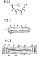
- This blank is formed by a chromel wire 2 and d 'other hand, by a portion of chromel wire 3 welded to one end of a portion of alumel wire 4 by a weld 5.
- These two sets of son have a diameter of about 1.5 mm.
- This set of two wires is embedded in a ceramic insulating material constituted for example by alumina or powdered magnesia, this insulator bearing the reference 6.
- An outer sheath of stainless steel 8 surrounds the ceramic insulator.
- This blank has an outside diameter of the order of 13 mm.
- a drawing operation is applied to this blank which makes it possible to reduce the initial external diameter from 13 mm to a final diameter of 1 or 0.5 mm.
- the problem associated with this operation is that, even if the welding 5 is carried out by known means with very high precision, due to the drawing, this welding 5 is very considerably elongated.
- a stack of an alumel wire 10 and a chromel wire 12 is produced, the two wires being placed end to end.
- This stack is housed inside an enclosure constituted by an external tube 14 made of molybdenum.
- This enclosure is completed by two plugs 16 and 18 also made of molybdenum which are fixed to the tube by the pins 20 also made of molybdenum.
- the tube 14 has a sufficient internal bore so that one can interpose between the stack of wires 10 and 12 and the tube itself a internal sleeve 22 in alumina.
- the distance separating the plugs 16 and 18 is sufficient so that it is possible to interpose between the ends respectively of the wires 10 and 12 of the cylinders 24 and 26 forming spacers also made of alumina. These cylinders 24 and 26 bear respectively on the plugs 18 and 16 and on the ends of the wires 10 and 12.
- the assembly thus produced is subjected to heating at a temperature of the order of 1100 ° C. for a period of between half an hour and 1 hour.
- a diffusion junction is obtained between the aluminum wire 10 and the chromel wire 12 at their contact interface 30.
- Alumel and chromel on the one hand and molybdenum have very different coefficients of thermal expansion. More specifically, the coefficient of thermal expansion of chromel and alumel is two to three times greater than that of molybdenum.
- the thickness of the weld thus obtained is of the order of a micron. Even if we admit that this weld in fact has a length of the order of 5 microns, we would obtain, after transformation of the blanks by drawing to reduce the outside diameter to the dimensions indicated above, lengths of the following welds. In the case of a complete differential thermocouple having an outside diameter of 1 mm, the weld length is 0.35 mm. To obtain a differential thermocouple with an outside diameter of 0.5 mm, the weld length is 1.4 mm.
- the length of weld between the chromel and the alumel obtained by the implementation of the method according to the invention is incommensurate with the lengths of weld obtained by the known methods. More specifically, it can be indicated that there is a factor of 100 between the length of weld obtained by the conventional methods and the length of weld obtained by the method according to the invention.
- thermocouple is obtained making it possible to obtain very precise measurements of the heating y in the core of the nuclear reactor.
- molybdenum would also be used to produce the enclosure 14 and temperatures of the same order would be used.
- the platinum-stainless steel connection is made by the same process.
- the only difference in obtaining the complete probe is that there is only one weld.
Landscapes
- Physics & Mathematics (AREA)
- General Physics & Mathematics (AREA)
- Health & Medical Sciences (AREA)
- Life Sciences & Earth Sciences (AREA)
- High Energy & Nuclear Physics (AREA)
- Molecular Biology (AREA)
- Spectroscopy & Molecular Physics (AREA)
- Measuring Temperature Or Quantity Of Heat (AREA)
Applications Claiming Priority (2)
| Application Number | Priority Date | Filing Date | Title |
|---|---|---|---|
| FR7927454A FR2469807A1 (fr) | 1979-11-07 | 1979-11-07 | Procede de realisation d'une jonction entre deux fils metalliques de dimension tres reduite et dispositifs de mesure realises a partir de cette jonction |
| FR7927454 | 1979-11-07 |
Publications (2)
| Publication Number | Publication Date |
|---|---|
| EP0028976A1 EP0028976A1 (fr) | 1981-05-20 |
| EP0028976B1 true EP0028976B1 (fr) | 1987-03-11 |
Family
ID=9231390
Family Applications (1)
| Application Number | Title | Priority Date | Filing Date |
|---|---|---|---|
| EP80401582A Expired EP0028976B1 (fr) | 1979-11-07 | 1980-11-05 | Procédé de réalisation d'une jonction entre deux fils métalliques de dimension très réduite |
Country Status (5)
| Country | Link |
|---|---|
| US (1) | US4415758A (OSRAM) |
| EP (1) | EP0028976B1 (OSRAM) |
| JP (1) | JPS56115578A (OSRAM) |
| DE (1) | DE3071922D1 (OSRAM) |
| FR (1) | FR2469807A1 (OSRAM) |
Families Citing this family (12)
| Publication number | Priority date | Publication date | Assignee | Title |
|---|---|---|---|---|
| US4659898A (en) * | 1985-02-07 | 1987-04-21 | Westinghouse Electric Corp. | Method of attaching a thermocouple to a metal surface |
| US5043023A (en) * | 1986-09-08 | 1991-08-27 | Commonwealth Scientific And Industrial Research Organization | Stable metal-sheathed thermocouple cable |
| US4819859A (en) * | 1987-12-18 | 1989-04-11 | Ppg Industries, Inc. | Lamination of oxide dispersion strengthened platinum and alloys |
| DE3823760A1 (de) * | 1988-07-13 | 1990-01-18 | Peroxid Chemie Gmbh | Ventilmetall/platinverbundelektrode |
| US5275670A (en) * | 1993-07-06 | 1994-01-04 | The United States Of America As Represented By The Administrator Of The National Aeronautics And Space Administration | High temperature, oxidation resistant noble metal-Al alloy thermocouple |
| DE10030354A1 (de) * | 2000-06-21 | 2002-01-10 | Bosch Gmbh Robert | Thermoelektrisches Bauelement |
| DE102010063474B4 (de) * | 2010-12-20 | 2014-02-13 | BSH Bosch und Siemens Hausgeräte GmbH | Kerntemperaturfühler |
| DE102011054803B4 (de) * | 2011-10-25 | 2014-07-24 | Günther Heisskanaltechnik Gmbh | Heißkanaldüse mit einer Heizung und mit einem Thermoelement |
| JP6752556B2 (ja) * | 2015-07-31 | 2020-09-09 | 株式会社フルヤ金属 | 熱電対の取り付け構造及び熱電対の取り付け方法 |
| EP3182083B1 (de) * | 2015-12-18 | 2018-09-19 | ENDRESS + HAUSER WETZER GmbH + Co. KG | Multipoint-sensor zur bestimmung eines bestehenden temperaturprofils eines mediums und verfahren zu dessen herstellung |
| CN114589499B (zh) * | 2020-12-03 | 2023-01-20 | 中核核电运行管理有限公司 | 堆芯热电偶在线更换方法 |
| JP7625184B1 (ja) * | 2023-07-25 | 2025-02-03 | 住友電気工業株式会社 | ウエハ加熱装置、およびウエハ加熱方法 |
Family Cites Families (11)
| Publication number | Priority date | Publication date | Assignee | Title |
|---|---|---|---|---|
| FR974021A (fr) * | 1948-09-09 | 1951-02-16 | Cie Des Forges De Chatillon | Perfectionnements aux couples thermo-électriques |
| US3049577A (en) * | 1959-08-28 | 1962-08-14 | Engelhard Ind Inc | Composite material and thermocouple made therefrom |
| US3065286A (en) * | 1958-07-25 | 1962-11-20 | Conax Corp | Thermocouple unit |
| BE636187A (OSRAM) * | 1962-08-14 | |||
| GB1131145A (en) * | 1966-05-18 | 1968-10-23 | Atomic Energy Authority Uk | Improvements in or relating thermoelectric devices |
| US3451859A (en) * | 1967-08-31 | 1969-06-24 | Engelhard Ind Inc | Noble metal thermocouple having base metal compensating leads |
| US3457122A (en) * | 1967-11-27 | 1969-07-22 | Hoskins Mfg Co | Nickel alloy thermocouple |
| US3673003A (en) * | 1969-09-18 | 1972-06-27 | Driver Co Wilbur B | Thermocouple for nuclear environment |
| US3703032A (en) * | 1970-08-14 | 1972-11-21 | Trw Inc | Diffusion bonding process |
| LU67219A1 (OSRAM) * | 1973-03-15 | 1973-05-22 | ||
| US4121749A (en) * | 1976-03-31 | 1978-10-24 | Electro-Nite Co. | Method of making thermocouple |
-
1979
- 1979-11-07 FR FR7927454A patent/FR2469807A1/fr active Granted
-
1980
- 1980-11-04 US US06/203,948 patent/US4415758A/en not_active Expired - Lifetime
- 1980-11-05 EP EP80401582A patent/EP0028976B1/fr not_active Expired
- 1980-11-05 DE DE8080401582T patent/DE3071922D1/de not_active Expired
- 1980-11-07 JP JP15755680A patent/JPS56115578A/ja active Pending
Also Published As
| Publication number | Publication date |
|---|---|
| US4415758A (en) | 1983-11-15 |
| EP0028976A1 (fr) | 1981-05-20 |
| JPS56115578A (en) | 1981-09-10 |
| FR2469807B1 (OSRAM) | 1983-08-05 |
| FR2469807A1 (fr) | 1981-05-22 |
| DE3071922D1 (en) | 1987-04-16 |
Similar Documents
| Publication | Publication Date | Title |
|---|---|---|
| EP0028976B1 (fr) | Procédé de réalisation d'une jonction entre deux fils métalliques de dimension très réduite | |
| FR2659445A1 (fr) | Element sensible a la temperature, et sonde de mesure comportant un tel element. | |
| EP0544367B1 (fr) | Capteur capacitif ayant une face avant conductrice pour former une armature de condensateur, et un câble coaxial blindé à isolant minéral | |
| FR3034867A1 (fr) | Eprouvette pour mesure d'echauffement nucleaire dans un reacteur nucleaire, et cellule calorimetrique comprenant au moins une telle eprouvette | |
| FR3016695A1 (fr) | Capteur de temperature pour temperature elevee | |
| FR2923073A1 (fr) | Bobine apte a generer un champ magnetique et procede de fabrication de ladite bobine. | |
| US5048973A (en) | Plug-type heat flux gauge | |
| EP0669516A1 (fr) | Procédé et dispositif de contrôle par ultrasons de facettes sur la surface intérieure de la paroi d'une gaine | |
| FR2634577A1 (fr) | Sommier pour un coeur de reacteur nucleaire et son procede de fabricatio | |
| FR2563937A1 (fr) | Cables stables a haute temperature et dispositifs comportant de tels cables | |
| US5086204A (en) | Method of producing a plug-type heat flux gauge | |
| Sandlin et al. | Use of brazing technique for manufacturing of high temperature fibre optical temperature and displacement transducer | |
| FR2559299A1 (fr) | Capteur a temps de reponse reduit pour prise de temperature a l'interieur d'une boucle du fluide de refroidissement des reacteurs nucleaires a eau pressurisee | |
| FR3030731A1 (fr) | Outil et procede de pose d'un thermocouple | |
| EP4016549B1 (fr) | Noyau de mesure pour la mesure d'echauffement nucleaire en reacteur nucleaire et capteur calorimetrique integrant un tel noyau de mesure | |
| WO2018002546A1 (fr) | Thermocouple avec protection de la jonction chaude | |
| EP4367491A1 (fr) | Procede de determination d'une deformation d'une zone d'une piece obtenue par fabrication additive | |
| Grossman | Ultrasonic-thermometry development for in-situ measurement of nuclear-fuel temperatures (AWBA Development Program) | |
| EP4423469B1 (fr) | Module de puissance à composants semi-conducteurs intégrant un capteur de température et procédé de fabrication associé | |
| FR2796452A1 (fr) | Procede de mesure de la temperature a l'interieur d'un four de traitement thermique | |
| FR3096134A1 (fr) | Dispositif de mesure des hautes températures adapté à un environnement corrosif métallique et oxyde à l’état liquide | |
| FR2984582A1 (fr) | Procede de soudage par resistance d'un bouchon sur une gaine d'un crayon de combustible | |
| FR2929012A1 (fr) | Capteur de mesure thermique | |
| WO2023052546A1 (fr) | Dispositif et procede de suivi d' une piece par reflectometrie | |
| FR2496871A1 (fr) | Procede et dispositif de mesure de faibles distances entre deux pieces metalliques |
Legal Events
| Date | Code | Title | Description |
|---|---|---|---|
| PUAI | Public reference made under article 153(3) epc to a published international application that has entered the european phase |
Free format text: ORIGINAL CODE: 0009012 |
|
| AK | Designated contracting states |
Designated state(s): BE DE GB IT NL SE |
|
| 17P | Request for examination filed |
Effective date: 19811026 |
|
| GRAA | (expected) grant |
Free format text: ORIGINAL CODE: 0009210 |
|
| AK | Designated contracting states |
Kind code of ref document: B1 Designated state(s): BE DE GB IT NL SE |
|
| REF | Corresponds to: |
Ref document number: 3071922 Country of ref document: DE Date of ref document: 19870416 |
|
| ITF | It: translation for a ep patent filed | ||
| PGFP | Annual fee paid to national office [announced via postgrant information from national office to epo] |
Ref country code: NL Payment date: 19871130 Year of fee payment: 8 |
|
| PLBE | No opposition filed within time limit |
Free format text: ORIGINAL CODE: 0009261 |
|
| STAA | Information on the status of an ep patent application or granted ep patent |
Free format text: STATUS: NO OPPOSITION FILED WITHIN TIME LIMIT |
|
| 26N | No opposition filed | ||
| PGFP | Annual fee paid to national office [announced via postgrant information from national office to epo] |
Ref country code: GB Payment date: 19890131 Year of fee payment: 8 |
|
| PG25 | Lapsed in a contracting state [announced via postgrant information from national office to epo] |
Ref country code: GB Effective date: 19891105 |
|
| PG25 | Lapsed in a contracting state [announced via postgrant information from national office to epo] |
Ref country code: SE Effective date: 19891106 |
|
| PG25 | Lapsed in a contracting state [announced via postgrant information from national office to epo] |
Ref country code: BE Effective date: 19891130 |
|
| BERE | Be: lapsed |
Owner name: COMMISSARIAT A L'ENERGIE ATOMIQUE ETABLISSEMENT D Effective date: 19891130 |
|
| PG25 | Lapsed in a contracting state [announced via postgrant information from national office to epo] |
Ref country code: NL Effective date: 19900601 |
|
| GBPC | Gb: european patent ceased through non-payment of renewal fee | ||
| NLV4 | Nl: lapsed or anulled due to non-payment of the annual fee | ||
| PG25 | Lapsed in a contracting state [announced via postgrant information from national office to epo] |
Ref country code: DE Effective date: 19900801 |
|
| EUG | Se: european patent has lapsed |
Ref document number: 80401582.4 Effective date: 19900705 |