EP0028970B1 - Dispositif de fixation de turboréacteurs multiflux - Google Patents
Dispositif de fixation de turboréacteurs multiflux Download PDFInfo
- Publication number
- EP0028970B1 EP0028970B1 EP80401563A EP80401563A EP0028970B1 EP 0028970 B1 EP0028970 B1 EP 0028970B1 EP 80401563 A EP80401563 A EP 80401563A EP 80401563 A EP80401563 A EP 80401563A EP 0028970 B1 EP0028970 B1 EP 0028970B1
- Authority
- EP
- European Patent Office
- Prior art keywords
- arm
- envelope
- attachment
- secondary flow
- exhaust casing
- Prior art date
- Legal status (The legal status is an assumption and is not a legal conclusion. Google has not performed a legal analysis and makes no representation as to the accuracy of the status listed.)
- Expired
Links
Images

Classifications
-
- B—PERFORMING OPERATIONS; TRANSPORTING
- B64—AIRCRAFT; AVIATION; COSMONAUTICS
- B64D—EQUIPMENT FOR FITTING IN OR TO AIRCRAFT; FLIGHT SUITS; PARACHUTES; ARRANGEMENT OR MOUNTING OF POWER PLANTS OR PROPULSION TRANSMISSIONS IN AIRCRAFT
- B64D27/00—Arrangement or mounting of power plants in aircraft; Aircraft characterised by the type or position of power plants
- B64D27/40—Arrangements for mounting power plants in aircraft
- B64D27/404—Suspension arrangements specially adapted for supporting vertical loads
-
- F—MECHANICAL ENGINEERING; LIGHTING; HEATING; WEAPONS; BLASTING
- F02—COMBUSTION ENGINES; HOT-GAS OR COMBUSTION-PRODUCT ENGINE PLANTS
- F02C—GAS-TURBINE PLANTS; AIR INTAKES FOR JET-PROPULSION PLANTS; CONTROLLING FUEL SUPPLY IN AIR-BREATHING JET-PROPULSION PLANTS
- F02C7/00—Features, components parts, details or accessories, not provided for in, or of interest apart form groups F02C1/00 - F02C6/00; Air intakes for jet-propulsion plants
- F02C7/20—Mounting or supporting of plant; Accommodating heat expansion or creep
-
- F—MECHANICAL ENGINEERING; LIGHTING; HEATING; WEAPONS; BLASTING
- F05—INDEXING SCHEMES RELATING TO ENGINES OR PUMPS IN VARIOUS SUBCLASSES OF CLASSES F01-F04
- F05D—INDEXING SCHEME FOR ASPECTS RELATING TO NON-POSITIVE-DISPLACEMENT MACHINES OR ENGINES, GAS-TURBINES OR JET-PROPULSION PLANTS
- F05D2230/00—Manufacture
- F05D2230/60—Assembly methods
- F05D2230/64—Assembly methods using positioning or alignment devices for aligning or centring, e.g. pins
- F05D2230/642—Assembly methods using positioning or alignment devices for aligning or centring, e.g. pins using maintaining alignment while permitting differential dilatation
-
- F—MECHANICAL ENGINEERING; LIGHTING; HEATING; WEAPONS; BLASTING
- F05—INDEXING SCHEMES RELATING TO ENGINES OR PUMPS IN VARIOUS SUBCLASSES OF CLASSES F01-F04
- F05D—INDEXING SCHEME FOR ASPECTS RELATING TO NON-POSITIVE-DISPLACEMENT MACHINES OR ENGINES, GAS-TURBINES OR JET-PROPULSION PLANTS
- F05D2230/00—Manufacture
- F05D2230/60—Assembly methods
- F05D2230/64—Assembly methods using positioning or alignment devices for aligning or centring, e.g. pins
- F05D2230/644—Assembly methods using positioning or alignment devices for aligning or centring, e.g. pins for adjusting the position or the alignment, e.g. wedges or eccenters
-
- Y—GENERAL TAGGING OF NEW TECHNOLOGICAL DEVELOPMENTS; GENERAL TAGGING OF CROSS-SECTIONAL TECHNOLOGIES SPANNING OVER SEVERAL SECTIONS OF THE IPC; TECHNICAL SUBJECTS COVERED BY FORMER USPC CROSS-REFERENCE ART COLLECTIONS [XRACs] AND DIGESTS
- Y10—TECHNICAL SUBJECTS COVERED BY FORMER USPC
- Y10T—TECHNICAL SUBJECTS COVERED BY FORMER US CLASSIFICATION
- Y10T74/00—Machine element or mechanism
- Y10T74/18—Mechanical movements
- Y10T74/18888—Reciprocating to or from oscillating
- Y10T74/1892—Lever and slide
- Y10T74/18952—Lever and slide toggle transmissions
-
- Y—GENERAL TAGGING OF NEW TECHNOLOGICAL DEVELOPMENTS; GENERAL TAGGING OF CROSS-SECTIONAL TECHNOLOGIES SPANNING OVER SEVERAL SECTIONS OF THE IPC; TECHNICAL SUBJECTS COVERED BY FORMER USPC CROSS-REFERENCE ART COLLECTIONS [XRACs] AND DIGESTS
- Y10—TECHNICAL SUBJECTS COVERED BY FORMER USPC
- Y10T—TECHNICAL SUBJECTS COVERED BY FORMER US CLASSIFICATION
- Y10T74/00—Machine element or mechanism
- Y10T74/20—Control lever and linkage systems
- Y10T74/20576—Elements
- Y10T74/20582—Levers
- Y10T74/20588—Levers toggle
Definitions
- the invention relates to a device for fixing, to a rigid support structure linked to an aircraft, the exhaust casing of the turbine of a turbojet engine with at least two flows, namely a central primary flow delimited by this casing d exhaust and a secondary flow delimited by a first envelope which surrounds this casing and which is fixed to this support structure.
- This device is of the type comprising a plurality of connecting members distributed around the exhaust casing. Each of these members is constituted by an arm, the section of which is suitably profiled to respond to the flow of the flow.
- This rigidity of the various connections in play means that, when a significant accidental imbalance appears during operation (imbalance due for example to the loss of a moving blade), the exhaust casing is subjected both to cyclic radial stresses exerted by the bearing and to the reactions of the rigid assembly and of great inertia constituted by the envelope of secondary flow and the supporting structure.
- the casing of the stator of the turbine, to which the exhaust casing belongs thus undergoes cyclic deformations.
- FR-A-2102187 relates to a mode of suspension of an engine of the double-flow type and describes the suspension members to the pylon of the aircraft. These organs are located in different transverse planes.
- One of these bodies made up of three connecting rods, opposes the torques acting on the central engine.
- This device does not provide sufficient elements to avoid the drawbacks noted above, or to allow, as is one of the aims of the invention, the internal connection between three concentric casings of an engine by a connection located in a same transverse plane.
- the object of the invention is to eliminate the causes of deformations noted above and consequently allow the radial clearance between the stator and the rotor to be reduced. It also provides facilities during the mounting of the secondary flow envelope around the exhaust casing and in particular in the application to a triple flow turbojet, it allows a separation between the central engine and two concentric envelopes by compensating for the mounting the stack of construction faults and mounting of the envelopes, for example boilers.
- the device of the invention is characterized in that the first means of attachment of each arm comprise on the one hand an arm articulation connecting a section of the arm to the first envelope of the secondary flow while leaving the arm a freedom of rotation in said transverse plane and on the other hand an adjustable length fastener oriented in this transverse plane and linked respectively, on the one hand, both to the first envelope of the secondary flow and of a second envelope external to the first and fixed to the supporting structure and on the other hand to another section of the arm by two attachment joints with freedom of rotation in this transverse plane and in that the second attachment means of each arm confer on the latter, relative to the casing exhaust, freedom of rotation in said transverse plane and freedom of translation in a direction of said plane passing through the vicinity of the axis of the turbine, and also leaving the arm relative to the card r exhaust, freedom of rotation in a plane parallel to the axis of the turbine.
- the invention thus makes it possible during assembly of the envelope of the secondary flow around the envelope of the stator and of the exhaust casing, to assign an optimal orientation to said arms of the fixing members.
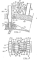
- FIGS. 1 and 2 are considered simultaneously. They show an external rigid ring 50 which constitutes the rear part of the envelope of the tertiary flow, an intermediate rigid ring 60 which constitutes the rear part of the envelope of the secondary flow and an internal ring formed by the exhaust casing 70 and which surrounds the cone 71 of the rear bearing support. This is fixed to the ring 70 by a plurality of rigid profiled arms 72.
- the ring 50 and the ring 60 are rigidly connected, on the one hand by the rear frame 80 suspended by rods 81 to a housing 82 (of which only the front flange is seen) secured to an aircraft mast not shown, on the other hand by a plurality of radial arms 61.
- the external ring 50 is connected to the front body of the envelope of the tertiary flow by a deformable tight connection constituted by an elastic bellows 62.
- the links 81 and the housing 82 are visible only in FIG. 1 and not in FIG. 2.
- the ring 70 is suspended in the ring 60 by four connecting members 90 which are described below with reference to FIGS. 4 and 5.
- the profiled box arm 91 crosses a passage 63 formed in the ring 60. It is provided with a yoke 92 which allows it to pivot around an axis 64 housed in the passage 63 and oriented parallel to the axis of the turbine. The arm 91 is therefore provided with a freedom of rotation in a plane transverse to the axis of the turbine.
- yokes 93 coaxial crossed by an axis 94 parallel to the axis 64.
- the fixed arm in profiled box 61 carries towards its section median, opposite the yokes 93, a plurality of yokes 65 crossed by an axis 66 which is also parallel to the axis 64.
- the axis 94 supports by their ends a first pair of rods 95.
- the axis 66 supports by their ends a second pair of rods 95.
- a pair of pins 96 respectively connects a link from one pair to a link from the other pair.
- the axes 66 and 94 are therefore linked by a plurality of identical deformable parallelograms, each consisting of four rods 95. Washers 97 arranged on the axes 96 ensure the bracing of these parallelograms, the whole of which constitutes a parallelogram with deformable dihedrons ensuring the connection of an adjustable arm 91 and a fixed arm 61.
- each axis 96 open on either side of the rods 95 forming the bases of this parallelogram and each carry a binocular 98.
- the two binoculars which flank a same base are braced by two bolts 99 parallel to each other which are arranged on either side of the two corresponding axes 96 and which engage in threaded holes formed in these binoculars.
- the threads are reversed, as are the corresponding threads of the binoculars 98. It is therefore possible to adjust the mounting, by rotation of these bolts 99, the inclination of the arms 91.
- each arm 91 (arranged in the secondary flow) carries a cylindrical journal 101 (shown in dotted lines in FIG. 5), which engages with gentle friction in the bore formed in a ball joint 102.
- the latter fits into a spherical housing formed in a bearing 103 which can itself slide in a slide 73 secured to the casing 70 and oriented parallel to the axis of the turbine.
- each arm 91 can be force-fitted into the ball joint 102 and the freedom of axial translation of the arm 91 relative to the casing 70 is ensured by sliding of the pad 103 which is thus free to slide in both radial and axial directions in slide 73.
- connection dimensions determined to ensure the resumption of loads, vertical, horizontal, as well as the torques passing through this plane. It can be noted that the different parallelograms that they constitute form as many adjustable spacers adjusting the connection between the two envelopes constituting the stator.
Landscapes
- Engineering & Computer Science (AREA)
- Chemical & Material Sciences (AREA)
- Combustion & Propulsion (AREA)
- Aviation & Aerospace Engineering (AREA)
- Mechanical Engineering (AREA)
- General Engineering & Computer Science (AREA)
- Structures Of Non-Positive Displacement Pumps (AREA)
- Control Of Turbines (AREA)
- Exhaust Gas After Treatment (AREA)
- Physical Or Chemical Processes And Apparatus (AREA)
Applications Claiming Priority (2)
| Application Number | Priority Date | Filing Date | Title |
|---|---|---|---|
| FR7927771 | 1979-11-12 | ||
| FR7927771A FR2469566A1 (fr) | 1979-11-12 | 1979-11-12 | Perfectionnements aux dispositifs de fixation de turboreacteurs multiflux |
Publications (2)
| Publication Number | Publication Date |
|---|---|
| EP0028970A1 EP0028970A1 (fr) | 1981-05-20 |
| EP0028970B1 true EP0028970B1 (fr) | 1984-04-11 |
Family
ID=9231536
Family Applications (1)
| Application Number | Title | Priority Date | Filing Date |
|---|---|---|---|
| EP80401563A Expired EP0028970B1 (fr) | 1979-11-12 | 1980-11-03 | Dispositif de fixation de turboréacteurs multiflux |
Country Status (4)
| Country | Link |
|---|---|
| US (1) | US4441313A (cg-RX-API-DMAC10.html) |
| EP (1) | EP0028970B1 (cg-RX-API-DMAC10.html) |
| DE (1) | DE3067468D1 (cg-RX-API-DMAC10.html) |
| FR (1) | FR2469566A1 (cg-RX-API-DMAC10.html) |
Families Citing this family (27)
| Publication number | Priority date | Publication date | Assignee | Title |
|---|---|---|---|---|
| US4658579A (en) * | 1983-07-14 | 1987-04-21 | United Technologies Corporation | Load sharing for engine nacelle |
| JPH0717238B2 (ja) * | 1983-07-14 | 1995-03-01 | ユナイテツド・テクノロジ−ズ・コ−ポレイシヨン | 荷重分担アダプタを備えたガスタービンエンジン |
| US4571936A (en) * | 1985-07-10 | 1986-02-25 | The United States Of America As Represented By The Secretary Of The Air Force | Length adjustable strut link with low aerodynamic drag |
| GB2192233B (en) * | 1986-07-02 | 1990-11-28 | Rolls Royce Plc | A gas turbine engine load transfer structure |
| US5028001A (en) * | 1987-03-13 | 1991-07-02 | General Electric Company | Method of vibration isolating an aircraft engine |
| US4875655A (en) * | 1987-03-13 | 1989-10-24 | General Electric Company | Vibration isolating engine mount |
| US5351930A (en) * | 1992-08-11 | 1994-10-04 | Lord Corporation | Mounting for engines and the like |
| FR2706946B1 (fr) * | 1993-06-23 | 1995-07-28 | Soc Nat Detude Et De Construction De Moteurs Daviation Snecma | Tuyere d'echappement pseudo-bidimensionnelle |
| DE10037837C2 (de) | 2000-08-03 | 2002-08-01 | Mtu Aero Engines Gmbh | Aufhängung |
| JP4801373B2 (ja) * | 2005-05-16 | 2011-10-26 | 三菱重工業株式会社 | タービンの車室構造 |
| US7584621B2 (en) * | 2005-08-05 | 2009-09-08 | Siemens Energy, Inc. | Radially expanding turbine engine exhaust cylinder interface |
| EP2019914A4 (en) * | 2006-05-04 | 2013-08-14 | Volvo Aero Corp | DEVICE FOR SWIVING AT LEAST ONE SWIVELING ELEMENT IN A TURBO ENGINE |
| AU2007351593A1 (en) * | 2006-06-09 | 2008-10-23 | Bell Helicopter Textron Inc. | Engine exhaust system with directional nozzle |
| CN101466940B (zh) * | 2006-06-09 | 2012-03-21 | 贝尔直升机泰克斯特龙公司 | 发动机排放系统 |
| US7814753B2 (en) * | 2006-07-25 | 2010-10-19 | United Technologies Corporation | Low profile attachment hanger system for a cooling liner within a gas turbine engine swivel exhaust duct |
| EP1887209A3 (en) * | 2006-07-25 | 2010-11-17 | United Technologies Corporation | Hanger system for a cooling liner within a gas turbine engine exhaust duct |
| FR2905975B1 (fr) * | 2006-09-20 | 2008-12-05 | Snecma Sa | Conduite de soufflante pour une turbomachine. |
| US7726609B2 (en) * | 2007-03-16 | 2010-06-01 | The Boeing Company | High-performance low-noise aircraft exhaust systems and methods |
| FR2928180B1 (fr) * | 2008-02-28 | 2010-04-02 | Airbus France | Ensemble moteur pour aeronef comprenant une structure annulaire de transfert d'efforts entourant le carter central d'un turboreacteur. |
| FR2963390B1 (fr) * | 2010-07-30 | 2012-08-31 | Snecma | Turboreacteur lateral perfectionne pour limiter ses deformations |
| EP2964943B1 (en) * | 2013-03-06 | 2017-11-22 | United Technologies Corporation | Exhaust system having a flow path liner supported by structural duct segments |
| US10518891B2 (en) * | 2014-11-21 | 2019-12-31 | General Electric Company | Turbine engine assembly and method of manufacturing thereof |
| CN104948301A (zh) * | 2015-05-20 | 2015-09-30 | 西安交通大学 | 一种燃气轮机的热端支承 |
| FR3053660A1 (fr) * | 2016-07-08 | 2018-01-12 | Airbus Operations | Attache moteur d'aeronef comprenant au moins un ecrou transversal et aeronef comprenant ladite attache moteur |
| FR3060532B1 (fr) * | 2016-12-20 | 2019-05-31 | Airbus Operations | Ensemble moteur pour aeronef, comprenant des dispositifs elastiques souples de transmission d'efforts entre des capots de nacelle et une structure annulaire reliee au carter moteur par des bielles |
| FR3095233B1 (fr) * | 2019-04-16 | 2021-03-12 | Safran Aircraft Engines | Carter d'échappement d'une turbomachine à l'aérodynamisme amélioré |
| JP7352590B2 (ja) * | 2021-04-02 | 2023-09-28 | 三菱重工業株式会社 | ガスタービン |
Family Cites Families (8)
| Publication number | Priority date | Publication date | Assignee | Title |
|---|---|---|---|---|
| DE961151C (de) * | 1956-02-18 | 1957-04-04 | W Blume Ingenieurbuero Fuer Le | Anordnung von TL-Triebwerken an Flugzeugen |
| US2936999A (en) * | 1956-12-07 | 1960-05-17 | United Aircraft Corp | Tangential bearing supports |
| US2936978A (en) * | 1957-03-29 | 1960-05-17 | United Aircraft Corp | Rear engine mount |
| FR1198215A (fr) * | 1958-06-10 | 1959-12-04 | M Le Ministre De La Defense Na | Dispositif d'accouplement réglable, notamment de contre-fiches arrière de turbo-moteurs à gaz |
| US3327965A (en) * | 1965-09-27 | 1967-06-27 | Douglas Aircraft Inc | Flexible engine pylon |
| US3412560A (en) * | 1966-08-03 | 1968-11-26 | Gen Motors Corp | Jet propulsion engine with cooled combustion chamber, fuel heater, and induced air-flow |
| GB1318748A (en) * | 1970-08-11 | 1973-05-31 | Secr Defence | Gas turgine ducted fan engines for aircraft |
| GB1436796A (en) * | 1972-08-22 | 1976-05-26 | Mtu Muenchen Gmbh | Gas turbine ducted fan engines of multi-shaft and multi-flow construction |
-
1979
- 1979-11-12 FR FR7927771A patent/FR2469566A1/fr active Granted
-
1980
- 1980-11-03 DE DE8080401563T patent/DE3067468D1/de not_active Expired
- 1980-11-03 EP EP80401563A patent/EP0028970B1/fr not_active Expired
- 1980-11-06 US US06/204,582 patent/US4441313A/en not_active Expired - Lifetime
Also Published As
| Publication number | Publication date |
|---|---|
| US4441313A (en) | 1984-04-10 |
| FR2469566A1 (fr) | 1981-05-22 |
| EP0028970A1 (fr) | 1981-05-20 |
| FR2469566B1 (cg-RX-API-DMAC10.html) | 1984-11-09 |
| DE3067468D1 (en) | 1984-05-17 |
Similar Documents
| Publication | Publication Date | Title |
|---|---|---|
| EP0028970B1 (fr) | Dispositif de fixation de turboréacteurs multiflux | |
| EP1574429B1 (fr) | Suspension d'un moteur à la structure d'un avion | |
| EP2288542B1 (fr) | Système propulsif d'aéronef | |
| CA2281619C (fr) | Ensemble propulseur a capots de soufflante munis de securites de maintien et de positionnement, pour aeronefs | |
| EP1707487A1 (fr) | Suspension arrière de turboréacteur | |
| EP1929140B1 (fr) | Attache arrière d'un moteur d'aéronef à deux manilles | |
| EP1905689B1 (fr) | Système propusif intégré comportant un moteur à turboreacteur à double flux | |
| EP3039254B1 (fr) | Suspension isostatique d'un turboréacteur par double support arrière | |
| FR2965796A1 (fr) | Suspension d'un moteur a un mat d'aeronef comportant un arceau de suspension | |
| EP4087784B1 (fr) | Assemblage entre un pylône d'aéronef et une turbomachine | |
| EP2712392B1 (fr) | Suspension du canal de flux froid d'un turboréacteur par des biellettes et des chapes radiales sur le carter d'échappement | |
| CH662321A5 (fr) | Dispositif pour suspendre la nacelle d'un moteur d'avion a une structure portante. | |
| EP0733545B1 (fr) | Turboréacteur à double flux à nacelle flottante | |
| FR2645500A1 (fr) | Capotage mobile pour moteur d'avion | |
| FR2981046A1 (fr) | Ensemble propulsif d'aeronef | |
| EP0519822A1 (fr) | Structure de suspension arrière du carter d'échappement d'un turboréacteur | |
| FR3055001A1 (fr) | Systeme de changement de pas equipe de moyens de reglage du pas des pales et turbomachine correspondante | |
| EP4237325B1 (fr) | Ensemble propulsif d'aéronef comprenant une nacelle et une turbomachine indépendamment supportées par un élément de voilure ou de fuselage ou d'empennage | |
| WO2025120280A1 (fr) | Ensemble comportant une turbomachine d'aeronef et son pylone d'accrochage | |
| FR3059364A1 (fr) | Systeme de suspension d'un premier element annulaire dans un deuxieme element annulaire de turbomachine et turbomachine correspondante | |
| WO2014174222A1 (fr) | Structure de suspension d'un turbopropulseur a double helices non carenees sur un element structurel d'un aeronef | |
| FR2981048A1 (fr) | Pylone d'accrochage pour suspension de moteur d'aeronef, et suspension avec un tel pylone | |
| EP3728039B1 (fr) | Dispositif de suspension | |
| FR3039132A1 (fr) | Ensemble moteur a helice a axe horizontal pour aeronef | |
| FR3124493A1 (fr) | Ensemble propulsif comprenant des panneaux de bifurcation pendulaires |
Legal Events
| Date | Code | Title | Description |
|---|---|---|---|
| PUAI | Public reference made under article 153(3) epc to a published international application that has entered the european phase |
Free format text: ORIGINAL CODE: 0009012 |
|
| 17P | Request for examination filed |
Effective date: 19801106 |
|
| AK | Designated contracting states |
Designated state(s): DE FR GB IT SE |
|
| ITF | It: translation for a ep patent filed | ||
| GRAA | (expected) grant |
Free format text: ORIGINAL CODE: 0009210 |
|
| AK | Designated contracting states |
Designated state(s): DE FR GB IT SE |
|
| REF | Corresponds to: |
Ref document number: 3067468 Country of ref document: DE Date of ref document: 19840517 |
|
| PLBE | No opposition filed within time limit |
Free format text: ORIGINAL CODE: 0009261 |
|
| STAA | Information on the status of an ep patent application or granted ep patent |
Free format text: STATUS: NO OPPOSITION FILED WITHIN TIME LIMIT |
|
| 26N | No opposition filed | ||
| ITTA | It: last paid annual fee | ||
| EAL | Se: european patent in force in sweden |
Ref document number: 80401563.4 |
|
| PGFP | Annual fee paid to national office [announced via postgrant information from national office to epo] |
Ref country code: GB Payment date: 19971027 Year of fee payment: 18 |
|
| PGFP | Annual fee paid to national office [announced via postgrant information from national office to epo] |
Ref country code: DE Payment date: 19980130 Year of fee payment: 18 |
|
| PGFP | Annual fee paid to national office [announced via postgrant information from national office to epo] |
Ref country code: SE Payment date: 19981015 Year of fee payment: 19 Ref country code: FR Payment date: 19981015 Year of fee payment: 19 |
|
| PG25 | Lapsed in a contracting state [announced via postgrant information from national office to epo] |
Ref country code: GB Free format text: LAPSE BECAUSE OF NON-PAYMENT OF DUE FEES Effective date: 19981103 |
|
| GBPC | Gb: european patent ceased through non-payment of renewal fee |
Effective date: 19981103 |
|
| PG25 | Lapsed in a contracting state [announced via postgrant information from national office to epo] |
Ref country code: DE Free format text: LAPSE BECAUSE OF NON-PAYMENT OF DUE FEES Effective date: 19990901 |
|
| PG25 | Lapsed in a contracting state [announced via postgrant information from national office to epo] |
Ref country code: SE Free format text: LAPSE BECAUSE OF NON-PAYMENT OF DUE FEES Effective date: 19991104 |
|
| EUG | Se: european patent has lapsed |
Ref document number: 80401563.4 |
|
| PG25 | Lapsed in a contracting state [announced via postgrant information from national office to epo] |
Ref country code: FR Free format text: LAPSE BECAUSE OF NON-PAYMENT OF DUE FEES Effective date: 20000731 |
|
| REG | Reference to a national code |
Ref country code: FR Ref legal event code: ST |