EP0028576B2 - Joint de culasse pour moteur à combustion interne - Google Patents
Joint de culasse pour moteur à combustion interne Download PDFInfo
- Publication number
- EP0028576B2 EP0028576B2 EP80420106A EP80420106A EP0028576B2 EP 0028576 B2 EP0028576 B2 EP 0028576B2 EP 80420106 A EP80420106 A EP 80420106A EP 80420106 A EP80420106 A EP 80420106A EP 0028576 B2 EP0028576 B2 EP 0028576B2
- Authority
- EP
- European Patent Office
- Prior art keywords
- rings
- fire
- sheet
- reinforcements
- forming
- Prior art date
- Legal status (The legal status is an assumption and is not a legal conclusion. Google has not performed a legal analysis and makes no representation as to the accuracy of the status listed.)
- Expired
Links
- 238000002485 combustion reaction Methods 0.000 title description 5
- 230000002787 reinforcement Effects 0.000 claims description 23
- 229910052751 metal Inorganic materials 0.000 claims description 19
- 239000002184 metal Substances 0.000 claims description 19
- 238000007789 sealing Methods 0.000 claims description 13
- 238000000034 method Methods 0.000 claims description 9
- 229910000831 Steel Inorganic materials 0.000 claims description 7
- 238000002788 crimping Methods 0.000 claims description 7
- 239000010959 steel Substances 0.000 claims description 7
- RYGMFSIKBFXOCR-UHFFFAOYSA-N Copper Chemical compound [Cu] RYGMFSIKBFXOCR-UHFFFAOYSA-N 0.000 claims description 5
- 229910052782 aluminium Inorganic materials 0.000 claims description 5
- XAGFODPZIPBFFR-UHFFFAOYSA-N aluminium Chemical compound [Al] XAGFODPZIPBFFR-UHFFFAOYSA-N 0.000 claims description 5
- 239000000463 material Substances 0.000 claims description 5
- 239000010949 copper Substances 0.000 claims description 4
- 229910052802 copper Inorganic materials 0.000 claims description 4
- 229910001369 Brass Inorganic materials 0.000 claims description 3
- 239000010951 brass Substances 0.000 claims description 3
- 238000005520 cutting process Methods 0.000 claims description 3
- 238000003825 pressing Methods 0.000 claims 2
- 239000004411 aluminium Substances 0.000 claims 1
- 239000012858 resilient material Substances 0.000 claims 1
- 239000010425 asbestos Substances 0.000 description 3
- 238000005304 joining Methods 0.000 description 3
- 238000004519 manufacturing process Methods 0.000 description 3
- 229910052895 riebeckite Inorganic materials 0.000 description 3
- 230000015572 biosynthetic process Effects 0.000 description 2
- 239000000498 cooling water Substances 0.000 description 2
- 239000013013 elastic material Substances 0.000 description 2
- 239000012530 fluid Substances 0.000 description 2
- 239000007789 gas Substances 0.000 description 2
- 241001080024 Telles Species 0.000 description 1
- 240000008042 Zea mays Species 0.000 description 1
- 239000011889 copper foil Substances 0.000 description 1
- 238000003754 machining Methods 0.000 description 1
- 238000012856 packing Methods 0.000 description 1
- 230000003014 reinforcing effect Effects 0.000 description 1
- 229910001220 stainless steel Inorganic materials 0.000 description 1
- 239000010935 stainless steel Substances 0.000 description 1
Images
Classifications
-
- F—MECHANICAL ENGINEERING; LIGHTING; HEATING; WEAPONS; BLASTING
- F16—ENGINEERING ELEMENTS AND UNITS; GENERAL MEASURES FOR PRODUCING AND MAINTAINING EFFECTIVE FUNCTIONING OF MACHINES OR INSTALLATIONS; THERMAL INSULATION IN GENERAL
- F16J—PISTONS; CYLINDERS; SEALINGS
- F16J15/00—Sealings
- F16J15/02—Sealings between relatively-stationary surfaces
- F16J15/06—Sealings between relatively-stationary surfaces with solid packing compressed between sealing surfaces
- F16J15/10—Sealings between relatively-stationary surfaces with solid packing compressed between sealing surfaces with non-metallic packing
- F16J15/12—Sealings between relatively-stationary surfaces with solid packing compressed between sealing surfaces with non-metallic packing with metal reinforcement or covering
- F16J15/121—Sealings between relatively-stationary surfaces with solid packing compressed between sealing surfaces with non-metallic packing with metal reinforcement or covering with metal reinforcement
- F16J15/122—Sealings between relatively-stationary surfaces with solid packing compressed between sealing surfaces with non-metallic packing with metal reinforcement or covering with metal reinforcement generally parallel to the surfaces
- F16J15/123—Details relating to the edges of the packing
-
- Y—GENERAL TAGGING OF NEW TECHNOLOGICAL DEVELOPMENTS; GENERAL TAGGING OF CROSS-SECTIONAL TECHNOLOGIES SPANNING OVER SEVERAL SECTIONS OF THE IPC; TECHNICAL SUBJECTS COVERED BY FORMER USPC CROSS-REFERENCE ART COLLECTIONS [XRACs] AND DIGESTS
- Y10—TECHNICAL SUBJECTS COVERED BY FORMER USPC
- Y10T—TECHNICAL SUBJECTS COVERED BY FORMER US CLASSIFICATION
- Y10T156/00—Adhesive bonding and miscellaneous chemical manufacture
- Y10T156/10—Methods of surface bonding and/or assembly therefor
- Y10T156/1052—Methods of surface bonding and/or assembly therefor with cutting, punching, tearing or severing
- Y10T156/1056—Perforating lamina
- Y10T156/1057—Subsequent to assembly of laminae
-
- Y—GENERAL TAGGING OF NEW TECHNOLOGICAL DEVELOPMENTS; GENERAL TAGGING OF CROSS-SECTIONAL TECHNOLOGIES SPANNING OVER SEVERAL SECTIONS OF THE IPC; TECHNICAL SUBJECTS COVERED BY FORMER USPC CROSS-REFERENCE ART COLLECTIONS [XRACs] AND DIGESTS
- Y10—TECHNICAL SUBJECTS COVERED BY FORMER USPC
- Y10T—TECHNICAL SUBJECTS COVERED BY FORMER US CLASSIFICATION
- Y10T428/00—Stock material or miscellaneous articles
- Y10T428/24—Structurally defined web or sheet [e.g., overall dimension, etc.]
- Y10T428/24273—Structurally defined web or sheet [e.g., overall dimension, etc.] including aperture
- Y10T428/24322—Composite web or sheet
Definitions
- the present invention relates to a method of manufacturing a cylinder head gasket for an internal combustion engine.
- the cylinder head gaskets are intended to be placed between an engine block and a cylinder head in order to ensure sealing against various fluids. This is how the cylinder head gasket must seal around the orifices which allow fluids such as cooling water and oil to circulate between the engine block and the cylinder head, and must also seal gases at the combustion chamber of each of the cylinders, requiring resistance to very high pressures and temperatures.
- fire rings obtained by cutting, stamping and crimping a metal sheet on the edge of the orifices made in the joint which is for its part made of an elastic material such as asbestos cardboard armed or not.
- Patent US-1 793424 describes a cylinder head gasket comprising a core covered, over its entire surface and on its two faces, by two metal plates, a lower metal plate and an upper metal plate. At each opening corresponding to a combustion chamber, the plate undergoes stamping and crimping operations ensuring the formation of wings forming the rings of fire.
- a metal insert is arranged, for example in the form of a copper foil, comprising wings turned upside down under the rings of fire.
- the inserts are positioned relative to the core and then the stamping of the inserts to form the wings at the openings.
- the upper cover plate then being positioned, a crimping of the inserts is carried out to form the wings coming to bear on the plate. It then proceeds to the establishment of the lower cover plate which in turn undergoes stamping and crimping operations.
- the present invention aims to remedy these drawbacks.
- a sealing plate made of elastic material such as a cardboard box of asbestos, armed or not, and fire rings obtained by cutting, stamping and crimping of a metal sheet on the edge of the orifices made in the sealing plate, reinforcements being provided between the.
- the reinforcements are arranged under each of the two faces of the fire rings and are obtained from a piece of material different from that from which the fire rings are made, and constituted by a thin metal strip of copper, brass, steel or aluminum applied to the face of the metal sheet corresponding to the inside of the setting forming each fire ring, is characterized in that it consists in joining the strip forming the reinforcements and the sheet forming the fire rings, to stamp and crimp around the orifices of the sealing plate, at the same time the strip and the sheet metal.
- this process consists of joining the strip forming the reinforcements and the sheet metal forming the fire rings by bonding.
- the metal strip has a thickness of between 0.02 and 0.15 mm.
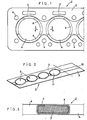
- the cylinder head gasket 2 shown in FIGS. 1 and 2 is constituted by a sealing plate 3 made of elastic and compressible material such as a possibly reinforced asbestos carton. It comprises orifices 4, generally circular, corresponding to the combustion chambers, orifices 5 intended for the passage of the engine cooling water and oil, as well as orifices 6 intended for the passage of the tightening holding studs of the breech.
- the orifices 4 are, as is known per se, surrounded by fittings 7 made of metal sheet, which constitute the rings of fire; they further comprise, according to the essential characteristic of the invention, reinforcements 8 located on the axis of least tightening and arranged on either side of the orifices 4. These reinforcements 8 are placed, as is clear in particular from the Figure 3, between the fire rings 7 and the plate 3, under each of the two faces of the rings.
- Figure 2 shows the metal sheet 9 from which the fire rings are made.
- This sheet which can be a sheet of copper, aluminum, stainless steel, aluminum clad steel, zinc-plated steel, tinned steel or other coated steels has in its central part and s extending over its entire length a reinforcement zone 10, corresponding to the zone of least tightening of the cylinder head gasket 2.
- This zone 10 possibly made integral with the sheet 9 by any means known per se, consists of a copper strip with a thickness of the order of 0.05 mm. It could also be a thin strip of brass, steel or aluminum.
- FIG. 2 shows the sheet metal 9 and reinforcement 10 complex after stamping ensuring the formation of generally circular orifices 11 with a diameter less than the diameter of the orifices 4 formed in the sealing plate 3.
- these orifices 11 are separated by reinforcement zones 10 arranged on either side of said orifices.
- the complex is cut out so as to provide bridges between the fire rings, then applied to the sealing plate 3 and crimped.
- the reinforcement 10 is then located inside the base crimped on either side of the sealing plate, covering the end of its upper and lower faces.
Landscapes
- Engineering & Computer Science (AREA)
- General Engineering & Computer Science (AREA)
- Mechanical Engineering (AREA)
- Gasket Seals (AREA)
Applications Claiming Priority (2)
| Application Number | Priority Date | Filing Date | Title |
|---|---|---|---|
| FR7927394A FR2468801A1 (fr) | 1979-10-31 | 1979-10-31 | Joint de culasse pour moteur a combustion interne |
| FR7927394 | 1979-10-31 |
Publications (3)
| Publication Number | Publication Date |
|---|---|
| EP0028576A1 EP0028576A1 (fr) | 1981-05-13 |
| EP0028576B1 EP0028576B1 (fr) | 1983-04-13 |
| EP0028576B2 true EP0028576B2 (fr) | 1986-09-10 |
Family
ID=9231360
Family Applications (1)
| Application Number | Title | Priority Date | Filing Date |
|---|---|---|---|
| EP80420106A Expired EP0028576B2 (fr) | 1979-10-31 | 1980-09-22 | Joint de culasse pour moteur à combustion interne |
Country Status (7)
| Country | Link |
|---|---|
| US (1) | US4330585A (enExample) |
| EP (1) | EP0028576B2 (enExample) |
| JP (1) | JPS5677536A (enExample) |
| DE (1) | DE3062760D1 (enExample) |
| ES (1) | ES495681A0 (enExample) |
| FR (1) | FR2468801A1 (enExample) |
| PT (1) | PT71930B (enExample) |
Families Citing this family (16)
| Publication number | Priority date | Publication date | Assignee | Title |
|---|---|---|---|---|
| DE3314237A1 (de) * | 1983-04-20 | 1984-10-31 | Goetze Ag, 5093 Burscheid | Zylinderkopfdichtung |
| DE3425075A1 (de) * | 1984-07-07 | 1986-01-16 | Goetze Ag, 5093 Burscheid | Zylinderkopfdichtung fuer verbrennungskraftmaschinen und ihr herstellungsverfahren |
| US4653761A (en) * | 1985-06-28 | 1987-03-31 | Cummins Engine Company, Inc. | Coolant flow orificing head gasket |
| DE3533359A1 (de) * | 1985-09-19 | 1987-03-26 | Lechler Elring Dichtungswerke | Zylinderkopfdichtung |
| US4662643A (en) * | 1986-04-14 | 1987-05-05 | Felt Products Mfg. Co. | Head gasket assembly for closely adjacent cylinder bores and method of making same |
| US4767124A (en) * | 1986-07-29 | 1988-08-30 | Ishikawa Gasket Co., Ltd. | Gasket for an internal combustion engine |
| JPH067216Y2 (ja) * | 1986-07-29 | 1994-02-23 | 石川ガスケット株式会社 | シリンダヘッド用金属非金属複合形ガスケット |
| US4815750A (en) * | 1988-06-08 | 1989-03-28 | Nihon Metal Gasket Kabushiki Kaisha | Metallic gasket with sealing beads |
| DE3922284A1 (de) * | 1989-07-06 | 1991-01-17 | Reinz Dichtungs Gmbh | Zylinderkopfdichtung |
| FR2667358B1 (fr) * | 1990-10-01 | 1994-12-23 | Meillor Sa | Joint de culasse a double sertissures. |
| JP2989282B2 (ja) * | 1991-01-09 | 1999-12-13 | 日本ガスケット株式会社 | 金属ガスケット |
| US5297806A (en) * | 1991-08-08 | 1994-03-29 | Dana Corporation | Method of making multi-density composite gaskets |
| CA2080103A1 (en) * | 1991-11-13 | 1993-05-14 | Joseph A. Pecina | Aluminum core cylinder head gasket for marine engines |
| GB2279895B (en) * | 1993-07-15 | 1996-03-06 | T & N Technology Ltd | Forming eyelets in gaskets |
| US5895057A (en) * | 1997-03-17 | 1999-04-20 | Fel-Pro Incorporated | Head gasket assembly for very closely adjacent cylinder bores with stabilized armoring and method of making same |
| US6669204B2 (en) | 2002-03-25 | 2003-12-30 | Federal-Mogul World Wide, Inc. | Cylinder head gasket having reinforced combustion seal |
Family Cites Families (8)
| Publication number | Priority date | Publication date | Assignee | Title |
|---|---|---|---|---|
| US1864854A (en) * | 1931-04-29 | 1932-06-28 | Victor Mfg & Gasket Co | Gasket |
| US2001225A (en) * | 1934-01-17 | 1935-05-14 | Victor Mfg & Gasket Co | Skeleton metal-backed gasket |
| DE2347321A1 (de) * | 1973-09-20 | 1975-03-27 | Goetzewerke | Flachdichtung, insbesondere zylinderkopfdichtung |
| JPS5425533Y2 (enExample) * | 1975-10-17 | 1979-08-25 | ||
| US4049856A (en) * | 1976-10-16 | 1977-09-20 | Tba Industrial Products Limited | Gaskets |
| US4272085A (en) * | 1978-10-07 | 1981-06-09 | Kawasaki Jukogyo Kabushiki Kaisha | Cylinder head gasket for a liquid cooled internal combustion engine |
| US4243231A (en) * | 1979-08-10 | 1981-01-06 | Ishino Gasket Mfg. Co., Ltd. | Gasket reinforced by grommet in combination with graphite sheet |
| US4254963A (en) * | 1979-12-04 | 1981-03-10 | Ex-Cell-O Corporation | Gasket assembly |
-
1979
- 1979-10-31 FR FR7927394A patent/FR2468801A1/fr active Granted
-
1980
- 1980-09-22 EP EP80420106A patent/EP0028576B2/fr not_active Expired
- 1980-09-22 DE DE8080420106T patent/DE3062760D1/de not_active Expired
- 1980-10-07 ES ES495681A patent/ES495681A0/es active Granted
- 1980-10-17 PT PT71930A patent/PT71930B/pt unknown
- 1980-10-30 JP JP15150780A patent/JPS5677536A/ja active Pending
- 1980-10-30 US US06/202,233 patent/US4330585A/en not_active Expired - Lifetime
Also Published As
| Publication number | Publication date |
|---|---|
| ES8106046A1 (es) | 1981-07-01 |
| FR2468801B1 (enExample) | 1982-02-19 |
| EP0028576A1 (fr) | 1981-05-13 |
| FR2468801A1 (fr) | 1981-05-08 |
| US4330585A (en) | 1982-05-18 |
| DE3062760D1 (en) | 1983-05-19 |
| PT71930B (fr) | 1981-08-31 |
| JPS5677536A (en) | 1981-06-25 |
| PT71930A (fr) | 1980-11-01 |
| ES495681A0 (es) | 1981-07-01 |
| EP0028576B1 (fr) | 1983-04-13 |
Similar Documents
| Publication | Publication Date | Title |
|---|---|---|
| EP0028576B2 (fr) | Joint de culasse pour moteur à combustion interne | |
| EP1023549B1 (fr) | Joint statique d'etancheite | |
| EP0086727B1 (fr) | Joint de culasse pour moteur à combustion interne | |
| EP0165879B1 (fr) | Joint de culasse | |
| FR2631412A1 (fr) | Joint d'etancheite feuillete en acier a bourrelets distincts | |
| FR2751029A1 (fr) | Silencieux de pot d'echappement | |
| EP0394145A1 (fr) | Procédé de fabricaton d'un joint comportant un corps métallique équipé d'au moins un élément d'étanchéité souple | |
| FR2636397A1 (fr) | Joint d'etancheite en acier lamine avec une large surface d'etancheite | |
| EP0310528B1 (fr) | Joint de culasse pour moteur à combustion interne | |
| EP1521019B1 (fr) | Joint multicouche comprenant au moins une cale de surépaisseur | |
| FR2742529A1 (fr) | Echangeur de chaleur a plaque collectrice sertie, notamment pour vehicule automobile | |
| EP0132418B1 (fr) | Procédé de fabrication d'une rampe d'injection de carburant | |
| EP0756114A1 (fr) | joint de culasse pour moteur à combustion interne | |
| EP0499551B1 (fr) | Joint de culasse pour moteur à combustion interne | |
| EP2255146B1 (fr) | Plaque collectrice sans gorge | |
| FR2524110A1 (fr) | Procede de fabrication d'un tube avec des conduits disposes dans sa paroi | |
| EP0487369A1 (fr) | Moteur à combustion interne comportant un joint de culasse | |
| FR2852543A1 (fr) | Procede de fixation d'une bride de raccordement sur un couvercle de collecteur d'un echangeur de chaleur | |
| FR2574891A1 (fr) | Procede de realisation d'un joint d'etancheite comportant un support metallique | |
| EP0483013A1 (fr) | Joint de culasse pour moteur à combustion interne | |
| EP0082090B1 (fr) | Joint de culasse pour moteur à combustion interne avec préchambre de combustion | |
| EP2309527A2 (fr) | Dispositif d'assemblage par brasage d'un capot d'extrémité sur un corps cylindrique et ampoule à vide comportant un tel dispositif | |
| FR2758591A1 (fr) | Bloc-cylindres pour moteur a combustion interne | |
| FR2742534A1 (fr) | Echangeur de chaleur a boite a fluide et plaque collectrice assemblees, notamment pour vehicule automobile | |
| FR2921431A3 (fr) | Joint de culasse |
Legal Events
| Date | Code | Title | Description |
|---|---|---|---|
| PUAI | Public reference made under article 153(3) epc to a published international application that has entered the european phase |
Free format text: ORIGINAL CODE: 0009012 |
|
| ITCL | It: translation for ep claims filed |
Representative=s name: JACOBACCI CASETTA & PERANI S.P.A. |
|
| AK | Designated contracting states |
Designated state(s): BE DE GB IT NL SE |
|
| 17P | Request for examination filed |
Effective date: 19810323 |
|
| DET | De: translation of patent claims | ||
| ITF | It: translation for a ep patent filed | ||
| GRAA | (expected) grant |
Free format text: ORIGINAL CODE: 0009210 |
|
| AK | Designated contracting states |
Designated state(s): BE DE GB IT NL SE |
|
| REF | Corresponds to: |
Ref document number: 3062760 Country of ref document: DE Date of ref document: 19830519 |
|
| PLBI | Opposition filed |
Free format text: ORIGINAL CODE: 0009260 |
|
| 26 | Opposition filed |
Opponent name: GOETZE AG Effective date: 19831008 |
|
| PLBI | Opposition filed |
Free format text: ORIGINAL CODE: 0009260 |
|
| 26 | Opposition filed |
Opponent name: ELRING DICHTUNGSWERKE GMBH Effective date: 19840107 |
|
| PGFP | Annual fee paid to national office [announced via postgrant information from national office to epo] |
Ref country code: DE Payment date: 19840803 Year of fee payment: 5 |
|
| PGFP | Annual fee paid to national office [announced via postgrant information from national office to epo] |
Ref country code: SE Payment date: 19840930 Year of fee payment: 5 Ref country code: BE Payment date: 19840930 Year of fee payment: 5 |
|
| PUAH | Patent maintained in amended form |
Free format text: ORIGINAL CODE: 0009272 |
|
| STAA | Information on the status of an ep patent application or granted ep patent |
Free format text: STATUS: PATENT MAINTAINED AS AMENDED |
|
| 27A | Patent maintained in amended form |
Effective date: 19860910 |
|
| AK | Designated contracting states |
Kind code of ref document: B2 Designated state(s): BE DE GB IT NL SE |
|
| ITF | It: translation for a ep patent filed | ||
| PGFP | Annual fee paid to national office [announced via postgrant information from national office to epo] |
Ref country code: NL Payment date: 19860930 Year of fee payment: 7 |
|
| NLR2 | Nl: decision of opposition | ||
| NLR3 | Nl: receipt of modified translations in the netherlands language after an opposition procedure | ||
| PG25 | Lapsed in a contracting state [announced via postgrant information from national office to epo] |
Ref country code: SE Effective date: 19870923 |
|
| PG25 | Lapsed in a contracting state [announced via postgrant information from national office to epo] |
Ref country code: BE Effective date: 19870930 |
|
| BERE | Be: lapsed |
Effective date: 19870930 |
|
| PG25 | Lapsed in a contracting state [announced via postgrant information from national office to epo] |
Ref country code: NL Effective date: 19880401 |
|
| NLV4 | Nl: lapsed or anulled due to non-payment of the annual fee | ||
| PG25 | Lapsed in a contracting state [announced via postgrant information from national office to epo] |
Ref country code: DE Effective date: 19880601 |
|
| GBPC | Gb: european patent ceased through non-payment of renewal fee | ||
| PG25 | Lapsed in a contracting state [announced via postgrant information from national office to epo] |
Ref country code: GB Free format text: LAPSE BECAUSE OF NON-PAYMENT OF DUE FEES Effective date: 19881118 |
|
| EUG | Se: european patent has lapsed |
Ref document number: 80420106.9 Effective date: 19880906 |