EP0028411B1 - Stopper for vials - Google Patents
Stopper for vials Download PDFInfo
- Publication number
- EP0028411B1 EP0028411B1 EP80106715A EP80106715A EP0028411B1 EP 0028411 B1 EP0028411 B1 EP 0028411B1 EP 80106715 A EP80106715 A EP 80106715A EP 80106715 A EP80106715 A EP 80106715A EP 0028411 B1 EP0028411 B1 EP 0028411B1
- Authority
- EP
- European Patent Office
- Prior art keywords
- cap
- inner cap
- flange
- stopper
- rubber plug
- Prior art date
- Legal status (The legal status is an assumption and is not a legal conclusion. Google has not performed a legal analysis and makes no representation as to the accuracy of the status listed.)
- Expired
Links
Images

Classifications
-
- B—PERFORMING OPERATIONS; TRANSPORTING
- B01—PHYSICAL OR CHEMICAL PROCESSES OR APPARATUS IN GENERAL
- B01L—CHEMICAL OR PHYSICAL LABORATORY APPARATUS FOR GENERAL USE
- B01L3/00—Containers or dishes for laboratory use, e.g. laboratory glassware; Droppers
- B01L3/50—Containers for the purpose of retaining a material to be analysed, e.g. test tubes
- B01L3/508—Containers for the purpose of retaining a material to be analysed, e.g. test tubes rigid containers not provided for above
- B01L3/5082—Test tubes per se
- B01L3/50825—Closing or opening means, corks, bungs
-
- B—PERFORMING OPERATIONS; TRANSPORTING
- B65—CONVEYING; PACKING; STORING; HANDLING THIN OR FILAMENTARY MATERIAL
- B65D—CONTAINERS FOR STORAGE OR TRANSPORT OF ARTICLES OR MATERIALS, e.g. BAGS, BARRELS, BOTTLES, BOXES, CANS, CARTONS, CRATES, DRUMS, JARS, TANKS, HOPPERS, FORWARDING CONTAINERS; ACCESSORIES, CLOSURES, OR FITTINGS THEREFOR; PACKAGING ELEMENTS; PACKAGES
- B65D51/00—Closures not otherwise provided for
- B65D51/24—Closures not otherwise provided for combined or co-operating with auxiliary devices for non-closing purposes
- B65D51/241—Closures not otherwise provided for combined or co-operating with auxiliary devices for non-closing purposes provided with freeze-drying means
Definitions
- This invention relates to a stopper for vials, and more particularly to a stopper for sealing off a vial by a simplified procedure without necessitating the step of crimping an aluminum cap.
- US-A-3 587 897 discloses a container closure comprising a cap of a cuplike form adapted to hold a stopper or liner in place in a container, said cap having a top including inner and outer portions. While the outer portion, i.e. a cover member may be made of a pliable material, such as plastic, the inner portion, i.e. the closure for holding the stopper in place has a generally cuplike form and is made out of sheet material such as aluminum.
- DE-A-2 405 169 describes a dropping dispenser to be fixed to a bottle by the user of the bottle.
- This dropping dispenser comprises two elements, i.e. an inner dropping insert to be introduced into the bottle opening and an outer cup for sealing the opening of the dropping insert.
- a stopper for vials is known as well, which comprises an aluminum outer cap for holding the stopper in place.
- Such so-called “flip-off caps” of aluminum are widely used for vials containing pharmaceutical preparations, especially powders or the like for preparing injection solutions.
- Such raps are costly since they are made of aluminum and, moreover, have the drawback of requiring a cumbersome vial closing process because the aluminum cap must be fitted to the vial by crimping after the vial has been sealed with a rubber plug pressed against the flange of the vial.
- Subject matter of this invention therefore is a stopper for a vial having a flange at its opening portion comprising a rubber plug having a top plate fittable to the flange in pressing contact therewith, an inner cap for receiving the rubber plug and having an upper wall formed with a hole in its center and an outer cap made of a flexible plastic fittable over the inner caps (as known from US-A-3587897), which is characterized in that the side wall of the inner cap comprises at least one projection on the inner peripheral surface thereof, the projection being fittable to the lower face of the flange with the top plate of the rubber plug held between the upper wall of the inner cap and the flange and at least one projection engageable with the top plate of the rubber plug on the inner surface of the inner cap side wall at its upper end; in that the outer cap has a side wall provided on its inner peripheral surface with a projection engageable with the outer peripheral surface of the inner cap side wall; and in that the inner cap is made of a flexible plastic.
- the stopper of this invention comprises an outer cap 1, an inner cap 2 and a rubber plug 3.
- the outer cap 1 includes an upper wall 1 a and a side wall 1 b integral therewith and formed with a projection 4 on its inner peripheral surface.
- the projection 4 is engageable with the outer periphery of the side wall 2b of the inner cap 2 to hold the outer cap 1 thereon.
- the inner cap 2 includes an upper wall 2a integral with the above-mentioned side wall 2b.
- the upper wall 2a is formed in its center with a hole 5 for permitting an injection needle to penetrate the rubber plug 3.
- Formed on the inner peripheral surface of the side wall 2b are two projections 6 which are fittable to the lower face of the flange 11 a of a vial 11 with the top plate 3a of the rubber plug 3 positioned between the upper wall 2a and the flange 11 a.
- Four projections 7 are provided on the inner surface of the side wall 2b at its upper end for engaging the top plate 3a of the rubber plug 3 to retain the plug 3 in the inner cap 2.
- the rubber plug 3 which is a rubber stopper heretofore used for vials, comprises the above-mentioned top plate 3a serving as a packing, and two legs 3b. Each of the legs has on its outer surface a projection 8 engageable with the opening portion of the vial 11.
- the outer cap 1 and the inner cap 2 are made of a flexible plastic, which is preferably polypropylene, polyethylene, polycarbonate or the like.
- the projection 4 on the outer cap 1 and the projections 6 and 7 on the inner cap 2 are not limitative in their arrangement but can be provided as desired insofar as they are serviceable as contemplated.
- the projections 6 on the inner cap 2 may be in the form of a continuous projection extending over the entire inner periphery of the inner cap side wall 2b like the projection 4 on the outer cap 1, or may be in the form of dots resembling the projections 7 on the inner cap 2.
- the stopper of this invention will be used in the following manner, for example, for a vial 11 for containing a freeze-dried preparation for injection.
- the inner cap 2 is fitted in the outer cap 1 in engagement with the projection 4, with the rubber plug 3 engaged with the projections 7 on the inner cap 2.
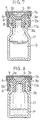
- the stopper is then placed on the vial 11 containing an aqueous solution S of the preparation so that the projections 8 on the rubber plug 3 bear on the opening portion of the vial 11 as seen in Fig. 7.
- the projections 6 on the inner cap 2 strike the upper edge of the flange 11 a on the vial 11, thereby forcing the side wall 2b of the inner cap 2 radially outward at its lower portion, and thereafter come into fitting engagement with the lower face of the flange 11 a, whereupon the inner cap side wall 2b restores itself.
- the vial 11 containing the powder P is completely sealed off as shown in Fig. 8.
- the vial stopper of this invention for which no aluminum material is used, can be manufactured at a low cost.
- the stopper is easy to use since it seals off the vial completely when simply pressed on. Because the sealing step can be performed subsequent to freeze-drying within a freeze-drying chamber in a continuous operation, the stopper is very useful for providing pharmaceutical products free from foreign matter and having an extremely low water content and a high quality.
Abstract
Description
- This invention relates to a stopper for vials, and more particularly to a stopper for sealing off a vial by a simplified procedure without necessitating the step of crimping an aluminum cap.
- US-A-3 587 897 discloses a container closure comprising a cap of a cuplike form adapted to hold a stopper or liner in place in a container, said cap having a top including inner and outer portions. While the outer portion, i.e. a cover member may be made of a pliable material, such as plastic, the inner portion, i.e. the closure for holding the stopper in place has a generally cuplike form and is made out of sheet material such as aluminum.
- DE-A-2 405 169 describes a dropping dispenser to be fixed to a bottle by the user of the bottle. This dropping dispenser comprises two elements, i.e. an inner dropping insert to be introduced into the bottle opening and an outer cup for sealing the opening of the dropping insert.
- From DE-B-2 361 350 a stopper for vials is known as well, which comprises an aluminum outer cap for holding the stopper in place.
- Such so-called "flip-off caps" of aluminum are widely used for vials containing pharmaceutical preparations, especially powders or the like for preparing injection solutions. Such raps are costly since they are made of aluminum and, moreover, have the drawback of requiring a cumbersome vial closing process because the aluminum cap must be fitted to the vial by crimping after the vial has been sealed with a rubber plug pressed against the flange of the vial.
- According to the present invention these drawbacks are overcome by providing a stopper for sealing off vials without using any aluminum material and also without resorting to the cumbersome crimping step needed for aluminum caps.
- Subject matter of this invention therefore is a stopper for a vial having a flange at its opening portion comprising a rubber plug having a top plate fittable to the flange in pressing contact therewith, an inner cap for receiving the rubber plug and having an upper wall formed with a hole in its center and an outer cap made of a flexible plastic fittable over the inner caps (as known from US-A-3587897), which is characterized in that the side wall of the inner cap comprises at least one projection on the inner peripheral surface thereof, the projection being fittable to the lower face of the flange with the top plate of the rubber plug held between the upper wall of the inner cap and the flange and at least one projection engageable with the top plate of the rubber plug on the inner surface of the inner cap side wall at its upper end; in that the outer cap has a side wall provided on its inner peripheral surface with a projection engageable with the outer peripheral surface of the inner cap side wall; and in that the inner cap is made of a flexible plastic.
- The subclaim covers a preferred embodiment of the stopper of the invention as defined above and in
claim 1. - A vial stopper embodying this invention will be described below with reference to be accompanying drawings, in which:
- Fig. 1 is a view in vertical section of an
outer cap 1; - Fig. 2 is a bottom view of the same;
- Fig. 3 is a view in vertical section of an inner cap 2;
- Fig. 4 is a bottom view of the sa.ne;
- Fig. 5 is a view in vertical section of a
rubber plug 3; - Fig. 6 is a bottom view of the same;
- Fig. 7 is a view in vertical section showing the stopper placed on the vial before the sealing step; and
- Fig. 8 is a view in vertical section showing the stopper after the sealing step.
- The stopper of this invention comprises an
outer cap 1, an inner cap 2 and arubber plug 3. - The
outer cap 1 includes anupper wall 1 a and aside wall 1 b integral therewith and formed with aprojection 4 on its inner peripheral surface. Theprojection 4 is engageable with the outer periphery of theside wall 2b of the inner cap 2 to hold theouter cap 1 thereon. - The inner cap 2 includes an
upper wall 2a integral with the above-mentionedside wall 2b. Theupper wall 2a is formed in its center with ahole 5 for permitting an injection needle to penetrate therubber plug 3. Formed on the inner peripheral surface of theside wall 2b are twoprojections 6 which are fittable to the lower face of theflange 11 a of avial 11 with thetop plate 3a of therubber plug 3 positioned between theupper wall 2a and theflange 11 a. Fourprojections 7 are provided on the inner surface of theside wall 2b at its upper end for engaging thetop plate 3a of therubber plug 3 to retain theplug 3 in the inner cap 2. - The
rubber plug 3, which is a rubber stopper heretofore used for vials, comprises the above-mentionedtop plate 3a serving as a packing, and twolegs 3b. Each of the legs has on its outer surface aprojection 8 engageable with the opening portion of thevial 11. - The
outer cap 1 and the inner cap 2 are made of a flexible plastic, which is preferably polypropylene, polyethylene, polycarbonate or the like. - The
projection 4 on theouter cap 1 and theprojections - For example, the
projections 6 on the inner cap 2 may be in the form of a continuous projection extending over the entire inner periphery of the innercap side wall 2b like theprojection 4 on theouter cap 1, or may be in the form of dots resembling theprojections 7 on the inner cap 2. - The stopper of this invention will be used in the following manner, for example, for a
vial 11 for containing a freeze-dried preparation for injection. - The inner cap 2 is fitted in the
outer cap 1 in engagement with theprojection 4, with therubber plug 3 engaged with theprojections 7 on the inner cap 2. The stopper is then placed on thevial 11 containing an aqueous solution S of the preparation so that theprojections 8 on therubber plug 3 bear on the opening portion of thevial 11 as seen in Fig. 7. When the stopper is pressed against the vial after the solution S has been freeze-dried to powder P, theprojections 6 on the inner cap 2 strike the upper edge of theflange 11 a on thevial 11, thereby forcing theside wall 2b of the inner cap 2 radially outward at its lower portion, and thereafter come into fitting engagement with the lower face of theflange 11 a, whereupon the innercap side wall 2b restores itself. Thus thevial 11 containing the powder P is completely sealed off as shown in Fig. 8. - The vial stopper of this invention, for which no aluminum material is used, can be manufactured at a low cost. The stopper is easy to use since it seals off the vial completely when simply pressed on. Because the sealing step can be performed subsequent to freeze-drying within a freeze-drying chamber in a continuous operation, the stopper is very useful for providing pharmaceutical products free from foreign matter and having an extremely low water content and a high quality.
Claims (2)
Priority Applications (1)
| Application Number | Priority Date | Filing Date | Title |
|---|---|---|---|
| AT80106715T ATE5958T1 (en) | 1979-11-01 | 1980-10-31 | STOPPER FOR BOTTLES. |
Applications Claiming Priority (2)
| Application Number | Priority Date | Filing Date | Title |
|---|---|---|---|
| JP14261279A JPS5664961A (en) | 1979-11-01 | 1979-11-01 | Plug body for vial |
| JP142612/79 | 1979-11-01 |
Publications (2)
| Publication Number | Publication Date |
|---|---|
| EP0028411A1 EP0028411A1 (en) | 1981-05-13 |
| EP0028411B1 true EP0028411B1 (en) | 1984-01-25 |
Family
ID=15319368
Family Applications (1)
| Application Number | Title | Priority Date | Filing Date |
|---|---|---|---|
| EP80106715A Expired EP0028411B1 (en) | 1979-11-01 | 1980-10-31 | Stopper for vials |
Country Status (5)
| Country | Link |
|---|---|
| EP (1) | EP0028411B1 (en) |
| JP (1) | JPS5664961A (en) |
| AT (1) | ATE5958T1 (en) |
| DE (1) | DE3066308D1 (en) |
| ES (1) | ES265665Y (en) |
Families Citing this family (20)
| Publication number | Priority date | Publication date | Assignee | Title |
|---|---|---|---|---|
| FR2516480B1 (en) * | 1981-11-13 | 1986-03-07 | Lyonnaise Bouchage | MEANS FOR SEALING A CONTAINER CONTAINING PRODUCTS FOR INJECTION |
| US4554125A (en) * | 1983-03-17 | 1985-11-19 | Schering Corporation | Method of making a stopper for a sterile fluid container |
| US4465200A (en) * | 1983-06-06 | 1984-08-14 | Becton, Dickinson And Company | Low contamination closure for blood collection tubes |
| JPS6096260U (en) * | 1983-12-05 | 1985-07-01 | 第一製薬株式会社 | medicinal bottle lid |
| JPS61178344U (en) * | 1985-04-24 | 1986-11-07 | ||
| US4697717A (en) * | 1986-08-18 | 1987-10-06 | Becton, Dickinson And Company | Rubber/plastic stopper composite with mechanical adhesive joints |
| JPS63180556U (en) * | 1987-05-12 | 1988-11-22 | ||
| CA2074505A1 (en) * | 1990-01-26 | 1991-07-27 | David M. Wong | Sanitary sampling system |
| CA2067691C (en) * | 1991-05-13 | 1995-12-12 | James A. Burns | Stopper-shield combination closure |
| US5823379A (en) * | 1993-10-20 | 1998-10-20 | Amersham International Plc | Sealed container for hazardous material |
| ATE195697T1 (en) | 1995-10-18 | 2000-09-15 | Daikyo Seiko Ltd | PLASTIC CAP AND METHOD FOR PRODUCING SAME |
| US5718348A (en) * | 1996-09-12 | 1998-02-17 | Comar, Inc. | Overcap assembly for gear finish vial |
| GB2312207B (en) * | 1996-10-25 | 1998-08-26 | Massmould Holdings | Plug closure assembly |
| US20060134354A1 (en) * | 2004-12-16 | 2006-06-22 | Walters Jay M | Calibration vial stopper with improved security features |
| US7543188B2 (en) * | 2005-06-29 | 2009-06-02 | Oracle International Corp. | Browser based remote control of functional testing tool |
| FR2912384B1 (en) * | 2007-02-09 | 2009-04-10 | Biocorp Rech Et Dev Sa | CLOSURE DEVICE FOR A CONTAINER, CONTAINER EQUIPPED WITH SUCH A DEVICE AND METHOD FOR CLOSING A LOT OF SUCH A CONTAINER |
| JP5479029B2 (en) * | 2009-10-30 | 2014-04-23 | 株式会社大協精工 | Combination of rubber stopper (B) for vial and plastic cap (C) |
| JP5683129B2 (en) * | 2010-04-30 | 2015-03-11 | 大和特殊硝子株式会社 | Vial stopper and seal member used therefor |
| FI20116059A (en) * | 2011-10-28 | 2013-04-29 | Thermo Fisher Scientific Oy | Reagent bottle, system, method and apparatus for handling closures and the like |
| WO2019125223A1 (en) * | 2017-12-21 | 2019-06-27 | Акционерное общество "Елатомский приборный завод" | Vacuum test tube |
Family Cites Families (10)
| Publication number | Priority date | Publication date | Assignee | Title |
|---|---|---|---|---|
| US1949902A (en) * | 1930-11-05 | 1934-03-06 | Owens Illinois Glass Co | Bottle closure |
| US3092278A (en) * | 1957-09-20 | 1963-06-04 | Astra Apotekarnes Kem Fab | Cap for a container for an injection liquid |
| US3073471A (en) * | 1960-03-17 | 1963-01-15 | Aluminum Co Of America | Closure device for sealed packages |
| US3746196A (en) * | 1971-01-29 | 1973-07-17 | Green Cross Corp | Coated plastic container for liquid medicine |
| BE794248A (en) * | 1972-02-22 | 1973-05-16 | Baxter Laboratories Inc | IMPROVEMENTS TO STERILE CLOSURES FOR SOLUTION BOTTLES OR VIALS |
| US3888377A (en) * | 1973-05-30 | 1975-06-10 | Reinhard Stadler | Closure cap for an infusion flask |
| DE2361350B1 (en) * | 1973-12-08 | 1975-05-28 | Matthias Faensen, Kleinmetallwarenfabrikation, 5190 Stolberg | Closure for pharmaceutical bottles |
| DE2405169A1 (en) * | 1974-02-04 | 1975-08-07 | Sanner Kg Friedr | Dropper insert for medicine bottles - has hollow bottle stopper with dropper tube fitting and cylindrical cap with inner bead |
| NL7707814A (en) * | 1976-08-03 | 1978-02-07 | Abbott Lab | PLASTIC HOLDERS. |
| US4211333A (en) * | 1978-06-05 | 1980-07-08 | Merck & Co., Inc. | Tamperproof container |
-
1979
- 1979-11-01 JP JP14261279A patent/JPS5664961A/en active Pending
-
1980
- 1980-10-31 ES ES1980265665U patent/ES265665Y/en not_active Expired
- 1980-10-31 EP EP80106715A patent/EP0028411B1/en not_active Expired
- 1980-10-31 DE DE8080106715T patent/DE3066308D1/en not_active Expired
- 1980-10-31 AT AT80106715T patent/ATE5958T1/en not_active IP Right Cessation
Also Published As
| Publication number | Publication date |
|---|---|
| ES265665U (en) | 1983-02-01 |
| EP0028411A1 (en) | 1981-05-13 |
| JPS5664961A (en) | 1981-06-02 |
| DE3066308D1 (en) | 1984-03-01 |
| ES265665Y (en) | 1983-07-16 |
| ATE5958T1 (en) | 1984-02-15 |
Similar Documents
| Publication | Publication Date | Title |
|---|---|---|
| EP0028411B1 (en) | Stopper for vials | |
| US4251003A (en) | Bottle closing device | |
| US5992660A (en) | Closure for vial container | |
| US3840152A (en) | Sealable and resealable container | |
| EP0592689B1 (en) | Vessel for drug | |
| US4194640A (en) | Vial and closure | |
| CA1103209A (en) | Vial and closure | |
| IE831276L (en) | A bottle and closure combination | |
| US4858760A (en) | Compound cap for use with a bottle | |
| US4995521A (en) | Stopper for infusion and transfusion bottles | |
| US4307817A (en) | Lid and container combination | |
| IE40324B1 (en) | Safety closure for bottles and like containers | |
| CA2022340A1 (en) | Retortable closure for plastic container | |
| US4274543A (en) | Vial and closure structure | |
| US4760936A (en) | Ventable container | |
| US4060911A (en) | Process for the preparation of a container closed under sterile conditions and containing lyophilized material | |
| US3313439A (en) | Closures for containers | |
| US4962852A (en) | Double-chambered container for liquids | |
| US4251002A (en) | Tamperproof container and closure | |
| EP0076418B1 (en) | Method for manufacturing sealed plastics containers, in particular flacons, vials, and/or the like, and containers obtained thereby | |
| WO1995034381A3 (en) | Perforable cap for a biological specimen container | |
| US3323276A (en) | Closures and methods for applying same | |
| US2561294A (en) | Closure for multiple dose vials | |
| CA1052732A (en) | Closable sterile container | |
| EP0051568A1 (en) | Lid for sealingly closing a container |
Legal Events
| Date | Code | Title | Description |
|---|---|---|---|
| PUAI | Public reference made under article 153(3) epc to a published international application that has entered the european phase |
Free format text: ORIGINAL CODE: 0009012 |
|
| AK | Designated contracting states |
Designated state(s): AT BE CH DE FR GB IT LU NL SE |
|
| 17P | Request for examination filed |
Effective date: 19810407 |
|
| ITF | It: translation for a ep patent filed |
Owner name: MODIANO & ASSOCIATI S.R.L. |
|
| GRAA | (expected) grant |
Free format text: ORIGINAL CODE: 0009210 |
|
| AK | Designated contracting states |
Designated state(s): AT BE CH DE FR GB IT LI LU NL SE |
|
| REF | Corresponds to: |
Ref document number: 5958 Country of ref document: AT Date of ref document: 19840215 Kind code of ref document: T |
|
| REF | Corresponds to: |
Ref document number: 3066308 Country of ref document: DE Date of ref document: 19840301 |
|
| ET | Fr: translation filed | ||
| PGFP | Annual fee paid to national office [announced via postgrant information from national office to epo] |
Ref country code: AT Payment date: 19841009 Year of fee payment: 5 |
|
| PGFP | Annual fee paid to national office [announced via postgrant information from national office to epo] |
Ref country code: FR Payment date: 19841026 Year of fee payment: 5 |
|
| PGFP | Annual fee paid to national office [announced via postgrant information from national office to epo] |
Ref country code: CH Payment date: 19841029 Year of fee payment: 5 |
|
| PG25 | Lapsed in a contracting state [announced via postgrant information from national office to epo] |
Ref country code: LU Free format text: LAPSE BECAUSE OF NON-PAYMENT OF DUE FEES Effective date: 19841031 |
|
| PGFP | Annual fee paid to national office [announced via postgrant information from national office to epo] |
Ref country code: DE Payment date: 19841102 Year of fee payment: 5 |
|
| PLBE | No opposition filed within time limit |
Free format text: ORIGINAL CODE: 0009261 |
|
| STAA | Information on the status of an ep patent application or granted ep patent |
Free format text: STATUS: NO OPPOSITION FILED WITHIN TIME LIMIT |
|
| PGFP | Annual fee paid to national office [announced via postgrant information from national office to epo] |
Ref country code: SE Payment date: 19841231 Year of fee payment: 5 Ref country code: BE Payment date: 19841231 Year of fee payment: 5 |
|
| 26N | No opposition filed | ||
| PG25 | Lapsed in a contracting state [announced via postgrant information from national office to epo] |
Ref country code: BE Effective date: 19851031 Ref country code: AT Effective date: 19851031 |
|
| PG25 | Lapsed in a contracting state [announced via postgrant information from national office to epo] |
Ref country code: SE Effective date: 19851101 |
|
| BERE | Be: lapsed |
Owner name: FUJISAWA PHARMACEUTICAL CO. LTD Effective date: 19851031 |
|
| PGFP | Annual fee paid to national office [announced via postgrant information from national office to epo] |
Ref country code: NL Payment date: 19871031 Year of fee payment: 8 |
|
| PG25 | Lapsed in a contracting state [announced via postgrant information from national office to epo] |
Ref country code: LI Effective date: 19881031 Ref country code: GB Effective date: 19881031 Ref country code: CH Effective date: 19881031 |
|
| PG25 | Lapsed in a contracting state [announced via postgrant information from national office to epo] |
Ref country code: NL Effective date: 19890501 |
|
| NLV4 | Nl: lapsed or anulled due to non-payment of the annual fee | ||
| PG25 | Lapsed in a contracting state [announced via postgrant information from national office to epo] |
Ref country code: FR Free format text: LAPSE BECAUSE OF NON-PAYMENT OF DUE FEES Effective date: 19890630 |
|
| REG | Reference to a national code |
Ref country code: CH Ref legal event code: PL |
|
| PG25 | Lapsed in a contracting state [announced via postgrant information from national office to epo] |
Ref country code: DE Effective date: 19890701 |
|
| GBPC | Gb: european patent ceased through non-payment of renewal fee | ||
| REG | Reference to a national code |
Ref country code: FR Ref legal event code: ST |
|
| EUG | Se: european patent has lapsed |
Ref document number: 80106715.8 Effective date: 19860805 |