EP0027424A1 - Séparateur hydraulique - Google Patents
Séparateur hydraulique Download PDFInfo
- Publication number
- EP0027424A1 EP0027424A1 EP80401464A EP80401464A EP0027424A1 EP 0027424 A1 EP0027424 A1 EP 0027424A1 EP 80401464 A EP80401464 A EP 80401464A EP 80401464 A EP80401464 A EP 80401464A EP 0027424 A1 EP0027424 A1 EP 0027424A1
- Authority
- EP
- European Patent Office
- Prior art keywords
- tank
- products
- liquid
- separator according
- separator
- Prior art date
- Legal status (The legal status is an assumption and is not a legal conclusion. Google has not performed a legal analysis and makes no representation as to the accuracy of the status listed.)
- Ceased
Links
Images


Classifications
-
- B—PERFORMING OPERATIONS; TRANSPORTING
- B03—SEPARATION OF SOLID MATERIALS USING LIQUIDS OR USING PNEUMATIC TABLES OR JIGS; MAGNETIC OR ELECTROSTATIC SEPARATION OF SOLID MATERIALS FROM SOLID MATERIALS OR FLUIDS; SEPARATION BY HIGH-VOLTAGE ELECTRIC FIELDS
- B03B—SEPARATING SOLID MATERIALS USING LIQUIDS OR USING PNEUMATIC TABLES OR JIGS
- B03B5/00—Washing granular, powdered or lumpy materials; Wet separating
- B03B5/48—Washing granular, powdered or lumpy materials; Wet separating by mechanical classifiers
- B03B5/54—Drag classifiers
Definitions
- the present invention relates to a new hydraulic separator which allows the separation of elements of different densities using a liquid such as water.
- a first category of apparatus for separating elements of different densities is constituted by hydro-classifiers which use the difference in sedimentation in a liquid, generally water. These devices, of simple design, can only be used to separate fine products from the fact that the classification of these products takes place by equivalence, that is to say by weight and not according to the density of the particles.
- a second category of apparatus consists of tables, dormant or shaking, which separate the products by entrainment of the less dense elements by a fluid film.
- the main drawback of these devices is that they only treat fine or relatively fine particles, that is to say with a diameter of less than 3 millimeters.
- pneumatic tables which are based on the principle of inclined vibrating lanes, the upward slope being the direction of movement of the products remaining in contact with the device.
- Light particles are fluidized by the air which passes through the table, moves away from it and is directed by this current of air towards the lower part of the pneumatic table.
- the densest products remain in contact and are stressed by vibrations: thus they raise the device and evacuate to its upper part.
- the materials to be classified are distributed over the surface of a fluid or suspension whose density is equal to that of separation, the higher density fraction precipitating while that of lower density floats. If the principle is simple, its practical application is quite complicated and requires the use of many auxiliary devices. These devices can classify products of any size, in theory at least.
- one of the aims of the present invention is a hydraulic separator which allows the densimetric separation of coarse and tormented particles.
- Another object of the invention is a separator of this type which is simple to adjust and easy to drive.
- An object of the present invention is a hydraulic separator which has no moving part in direct relation to the separation.
- Another object of this invention is a separator of this type which is robust, simple and of use economic.
- a hydraulic separator which is constituted by a rectangular cross-section tank of constant width and whose vertical section is a rectangular trapezoid, the large base corresponding to the upper part of this tank, which comprises at the upper end of its inclined side and below its upper edge a weir; a chimney which is extended at its upper part, situated below the level of the upper edge of this tank, by a chute for evacuating light elements; the separator also comprising a system for removing heavy elements, a device for injecting a liquid and means for introducing the products to be separated.
- the chimney is a parallelepiped with a square section, the upper edge opposite to the discharge chute is extended by the means for introducing the products to be separated which consist of a channel, slightly inclined relative to the horizontal.
- the system for removing heavy elements consists of a squeegee chain which is mounted on three rollers: one of them being located above the small base of the tank, the other two above this tank including one above the weir and one of the two being motor.
- this tank further comprises a deflector located under the chimney and above the deflection roller disposed above the small base of this tank, as well as two flaps fixed along the two faces of the tank so that heavy elements accumulate and remain on the squeegee path.
- the device for injecting a liquid it is preferably located at a point in the tank such that the arrival of the liquid does not interfere with the settling of heavy products.
- this tank has in its part a system of removable strips, which allows the adjustment of the separation of the products by increasing or decreasing the free level of the liquid used.
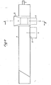
- a hydraulic separator according to the present invention referenced 1 as a whole is mounted on a frame 2.
- This hydraulic separator 1 is constituted by a tank 3 of rectangular cross section, of constant width and whose vertical section is a rectangular trapezoid. The large base thereof corresponds to the upper part 4 of this tank 3.
- the tank 3 comprises, on the one hand, a weir 5 which is located at the end of its inclined side 6 and, on the other hand, an inlet 7 under pressure of liquid such as water.
- a chimney 8 which is a rectangular parallelepiped is placed in the tank 3. It is extended at its upper part, which is located below the level of the upper edge of this tank 3, by a chute 9 to evacuate the light elements . Opposite this chute 9 is a channel 10 (FIG. 2) which is slightly inclined relative to the horizontal by which the products to be classified are introduced into the chimney 8.
- the hydraulic separator 1 comprises a recovery system for heavy elements which, according to this embodiment, consists of a squeegee chain 11 which is mounted on three rollers: the roller 12 which is located above the small base 13 of the tank 3, the roller 14 which is arranged above the weir 5 and which, in this embodiment, drives the squeegee chain 11, and the roller 15 being mounted vertically on the roller 12 and in the same horizontal plane as the roller 14. This roller 15 ensures the adjustment of the chain tension raclette 11.
- the tank has a deflector 16 located under the chimney 8 and above the roller 14, as well as, as shown in FIG. 3, two flaps 17 and 18 fixed along the two faces 19 and 20 of the tank 3 so that the heavy elements accumulate and remain in the path of the squeegees.
- the device 7 for injecting a liquid is, in this example, located on the side opposite the inclined plane at the level of the chimney 8 so that the arrival of the liquid does not interfere with the settling of heavy products.
- the tank 3 is provided at its upper part, for example on its face 19, with a system 21 of removable strips: this allows the adjustment of the separation of the products by increasing or decreasing the free level of the liquid used.
- the operating principle of the hydraulic separator 1 consists in canceling or reversing, at the top of the chimney 8, the action of the forces due to gravity on the products to be eliminated.
- the products to be classified are introduced into the stack 8 through the channel 10 tangentially to the surface of the liquid, therefore with a speed whose vertical component is almost zero. These products receive from the rising water stream in the chimney 8 a thrust equal to the weight of the elements of selected separation density.
- the system 21 of removable strips makes it possible to fix the level of overflow of the liquid and thereby to control the upward speed of this liquid in the stack 8: the closer the overflow level is to the upper edge of the tank 3, the higher the upward speed of the liquid.
Applications Claiming Priority (2)
| Application Number | Priority Date | Filing Date | Title |
|---|---|---|---|
| FR7925409 | 1979-10-12 | ||
| FR7925409A FR2467019A1 (fr) | 1979-10-12 | 1979-10-12 | Separateur hydraulique |
Publications (1)
| Publication Number | Publication Date |
|---|---|
| EP0027424A1 true EP0027424A1 (fr) | 1981-04-22 |
Family
ID=9230616
Family Applications (1)
| Application Number | Title | Priority Date | Filing Date |
|---|---|---|---|
| EP80401464A Ceased EP0027424A1 (fr) | 1979-10-12 | 1980-10-13 | Séparateur hydraulique |
Country Status (12)
| Country | Link |
|---|---|
| EP (1) | EP0027424A1 (da) |
| BR (1) | BR8006552A (da) |
| CS (1) | CS215004B2 (da) |
| DD (1) | DD153520A5 (da) |
| DK (1) | DK429280A (da) |
| ES (1) | ES8106094A1 (da) |
| FR (1) | FR2467019A1 (da) |
| MA (1) | MA18972A1 (da) |
| PL (1) | PL124697B1 (da) |
| PT (1) | PT71903B (da) |
| YU (1) | YU260480A (da) |
| ZA (1) | ZA806286B (da) |
Citations (4)
| Publication number | Priority date | Publication date | Assignee | Title |
|---|---|---|---|---|
| FR649499A (fr) * | 1927-03-22 | 1928-12-22 | Erz U Kohle Flotation G M B H | Procédé et dispositif pour le classement de mélanges de matières |
| US1871583A (en) * | 1930-04-12 | 1932-08-16 | Edgehill T Burnside | Gravel washing machine |
| US1883800A (en) * | 1932-03-11 | 1932-10-18 | Mclanahan & Stone Corp | Material washing machine |
| GB731531A (en) * | 1951-09-25 | 1955-06-08 | Hardinge Co | Improvements in or relating to the separation of materials having different settlingrates in liquid such as water |
-
1979
- 1979-10-12 FR FR7925409A patent/FR2467019A1/fr active Granted
-
1980
- 1980-10-07 MA MA19171A patent/MA18972A1/fr unknown
- 1980-10-10 CS CS806874A patent/CS215004B2/cs unknown
- 1980-10-10 ES ES495834A patent/ES8106094A1/es not_active Expired
- 1980-10-10 YU YU02604/80A patent/YU260480A/xx unknown
- 1980-10-10 DD DD80224479A patent/DD153520A5/de unknown
- 1980-10-10 PT PT71903A patent/PT71903B/pt unknown
- 1980-10-10 BR BR8006552A patent/BR8006552A/pt unknown
- 1980-10-10 DK DK429280A patent/DK429280A/da unknown
- 1980-10-11 PL PL1980227235A patent/PL124697B1/pl unknown
- 1980-10-13 EP EP80401464A patent/EP0027424A1/fr not_active Ceased
- 1980-10-13 ZA ZA00806286A patent/ZA806286B/xx unknown
Patent Citations (4)
| Publication number | Priority date | Publication date | Assignee | Title |
|---|---|---|---|---|
| FR649499A (fr) * | 1927-03-22 | 1928-12-22 | Erz U Kohle Flotation G M B H | Procédé et dispositif pour le classement de mélanges de matières |
| US1871583A (en) * | 1930-04-12 | 1932-08-16 | Edgehill T Burnside | Gravel washing machine |
| US1883800A (en) * | 1932-03-11 | 1932-10-18 | Mclanahan & Stone Corp | Material washing machine |
| GB731531A (en) * | 1951-09-25 | 1955-06-08 | Hardinge Co | Improvements in or relating to the separation of materials having different settlingrates in liquid such as water |
Also Published As
| Publication number | Publication date |
|---|---|
| MA18972A1 (fr) | 1981-07-01 |
| FR2467019B1 (da) | 1983-01-21 |
| DK429280A (da) | 1981-04-13 |
| ZA806286B (en) | 1981-11-25 |
| PT71903A (fr) | 1980-11-01 |
| PL227235A1 (da) | 1981-07-10 |
| CS215004B2 (en) | 1982-06-25 |
| FR2467019A1 (fr) | 1981-04-17 |
| ES495834A0 (es) | 1981-07-16 |
| PL124697B1 (en) | 1983-02-28 |
| DD153520A5 (de) | 1982-01-13 |
| PT71903B (fr) | 1981-08-14 |
| BR8006552A (pt) | 1981-04-14 |
| ES8106094A1 (es) | 1981-07-16 |
| YU260480A (en) | 1984-02-29 |
Similar Documents
| Publication | Publication Date | Title |
|---|---|---|
| FR2524819A1 (fr) | Procede et broyeur a meules verticales, pour le classement pneumatique des matieres broyees | |
| JP2000070859A (ja) | ポリシリコンのための空気篩分け | |
| FR2561141A1 (fr) | Appareil de separation vibrant | |
| EP0161995B1 (fr) | Procédé de traitement des sables de fonderie pour, notamment récupérer la chromite, ainsi que l'installation et les moyens de mise en oeuvre du procédé | |
| EP0027424A1 (fr) | Séparateur hydraulique | |
| EP2643100B1 (fr) | Dispositif et procede d'egouttage-rincage de matieres granulaires solides, riches en particules filiformes (i.e. des cables metalliques) | |
| JP2854894B2 (ja) | 洗い除きし選り分ける装置 | |
| US3777887A (en) | Apparatus for separating dry granular material | |
| FR2488155A1 (fr) | Procede et dispositif pour separer le sable de fragments de matieres vegetales | |
| US1869987A (en) | Separator | |
| US6044979A (en) | Device for separating superfine material from continuously fed granular solids | |
| FR2636863A1 (fr) | Installation de separation et de nettoyage de produits broyes | |
| FR2581899A1 (fr) | Dispositif pour l'enlevement par lavage d'impuretes organiques et argileuses melangees a des matieres solides a grains gros et fins amenees en continu | |
| FR2522523A1 (fr) | Installation pour la recuperation du sable siliceux contenu dans les eaux de lavage des graviers de sablieres | |
| FR2528159A1 (fr) | Procede et appareil pour le sechage de matieres pulverulentes en general | |
| EP3360407B1 (fr) | Grille pour nettoyeur de grains | |
| US2497884A (en) | Inclined current fluid suspension ore separator | |
| BE1006588A6 (fr) | Procede et installation pour le tri et la selection des dechets urbains. | |
| KR20230128870A (ko) | 폴리실리콘 순도 향상을 위한 이물제거 선별장치 | |
| EP3222367B1 (fr) | Procédé et installation de traitement de panneau ou plaque | |
| EP0041422B1 (fr) | Procédé et installation pour la préparation des ordures ménagères en vue de la production de compost | |
| BE416276A (da) | ||
| FR2564749A1 (fr) | Procede et installation pour le traitement des minerais d'or | |
| BE461343A (da) | ||
| BE515679A (da) |
Legal Events
| Date | Code | Title | Description |
|---|---|---|---|
| PUAI | Public reference made under article 153(3) epc to a published international application that has entered the european phase |
Free format text: ORIGINAL CODE: 0009012 |
|
| AK | Designated contracting states |
Designated state(s): AT BE CH DE FR GB IT LU NL SE |
|
| 17P | Request for examination filed |
Effective date: 19810413 |
|
| STAA | Information on the status of an ep patent application or granted ep patent |
Free format text: STATUS: THE APPLICATION HAS BEEN REFUSED |
|
| 18R | Application refused |
Effective date: 19831209 |
|
| RIN1 | Information on inventor provided before grant (corrected) |
Inventor name: MOUTTE, PAUL Inventor name: SAINTE-BEUVE, ROBERT |