EP0027407B1 - Dispositif pour détecter une différence entre les vitesses de rotation de deux arbres tournants et application à une mesure ou à une commande d'asservissement - Google Patents
Dispositif pour détecter une différence entre les vitesses de rotation de deux arbres tournants et application à une mesure ou à une commande d'asservissement Download PDFInfo
- Publication number
- EP0027407B1 EP0027407B1 EP80401413A EP80401413A EP0027407B1 EP 0027407 B1 EP0027407 B1 EP 0027407B1 EP 80401413 A EP80401413 A EP 80401413A EP 80401413 A EP80401413 A EP 80401413A EP 0027407 B1 EP0027407 B1 EP 0027407B1
- Authority
- EP
- European Patent Office
- Prior art keywords
- difference
- mobile arrangement
- rotational speed
- fly
- speeds
- Prior art date
- Legal status (The legal status is an assumption and is not a legal conclusion. Google has not performed a legal analysis and makes no representation as to the accuracy of the status listed.)
- Expired
Links
- 238000005259 measurement Methods 0.000 title description 2
- 230000001105 regulatory effect Effects 0.000 claims description 16
- 238000006073 displacement reaction Methods 0.000 claims description 15
- 230000005484 gravity Effects 0.000 claims description 6
- 230000000694 effects Effects 0.000 claims description 4
- 230000000750 progressive effect Effects 0.000 claims description 3
- 230000001419 dependent effect Effects 0.000 claims 2
- 230000010355 oscillation Effects 0.000 description 11
- 238000001514 detection method Methods 0.000 description 4
- 230000001276 controlling effect Effects 0.000 description 3
- 230000008878 coupling Effects 0.000 description 2
- 238000010168 coupling process Methods 0.000 description 2
- 238000005859 coupling reaction Methods 0.000 description 2
- 230000007935 neutral effect Effects 0.000 description 2
- 206010003830 Automatism Diseases 0.000 description 1
- 238000010276 construction Methods 0.000 description 1
- 239000000446 fuel Substances 0.000 description 1
- 230000003993 interaction Effects 0.000 description 1
- 238000005192 partition Methods 0.000 description 1
- 230000001960 triggered effect Effects 0.000 description 1
Images
Classifications
-
- F—MECHANICAL ENGINEERING; LIGHTING; HEATING; WEAPONS; BLASTING
- F01—MACHINES OR ENGINES IN GENERAL; ENGINE PLANTS IN GENERAL; STEAM ENGINES
- F01D—NON-POSITIVE DISPLACEMENT MACHINES OR ENGINES, e.g. STEAM TURBINES
- F01D17/00—Regulating or controlling by varying flow
- F01D17/02—Arrangement of sensing elements
- F01D17/06—Arrangement of sensing elements responsive to speed
-
- F—MECHANICAL ENGINEERING; LIGHTING; HEATING; WEAPONS; BLASTING
- F02—COMBUSTION ENGINES; HOT-GAS OR COMBUSTION-PRODUCT ENGINE PLANTS
- F02D—CONTROLLING COMBUSTION ENGINES
- F02D25/00—Controlling two or more co-operating engines
- F02D25/02—Controlling two or more co-operating engines to synchronise speed
-
- H—ELECTRICITY
- H02—GENERATION; CONVERSION OR DISTRIBUTION OF ELECTRIC POWER
- H02P—CONTROL OR REGULATION OF ELECTRIC MOTORS, ELECTRIC GENERATORS OR DYNAMO-ELECTRIC CONVERTERS; CONTROLLING TRANSFORMERS, REACTORS OR CHOKE COILS
- H02P5/00—Arrangements specially adapted for regulating or controlling the speed or torque of two or more electric motors
- H02P5/46—Arrangements specially adapted for regulating or controlling the speed or torque of two or more electric motors for speed regulation of two or more dynamo-electric motors in relation to one another
- H02P5/48—Arrangements specially adapted for regulating or controlling the speed or torque of two or more electric motors for speed regulation of two or more dynamo-electric motors in relation to one another by comparing mechanical values representing the speeds
-
- F—MECHANICAL ENGINEERING; LIGHTING; HEATING; WEAPONS; BLASTING
- F05—INDEXING SCHEMES RELATING TO ENGINES OR PUMPS IN VARIOUS SUBCLASSES OF CLASSES F01-F04
- F05D—INDEXING SCHEME FOR ASPECTS RELATING TO NON-POSITIVE-DISPLACEMENT MACHINES OR ENGINES, GAS-TURBINES OR JET-PROPULSION PLANTS
- F05D2200/00—Mathematical features
- F05D2200/10—Basic functions
- F05D2200/11—Sum
Definitions
- the invention relates to a device making it possible to detect a difference between the speeds of rotation of two rotating shafts, in particular in order to display this difference in speeds on an appropriate device, to perform a servo-control of the speed of rotation of one of the shafts as a function of the speed of rotation of the other shaft, or of triggering an automatic mechanism when the difference between the speeds of rotation of the two shafts reaches only one determined.
- each of the speeds of rotation is determined by means of an independent speed-of-rotation detector comprising weights which rotate with the 'corresponding shaft and act against an opposing spring to move a moving element, and the moving elements of the two rotational speed detectors are connected by a mechanism comprising in most cases a system of levers and at least one cam.
- a device of this type is described in US Patent No. 2,861,638 of September 19, 1957 to R. A. Grosselfinger and AI.
- Such devices have the drawback of being complex, since they include two independent speed detectors each comprising a moving element and an opposing spring, as well as an intermediate mechanism connecting the moving elements of each of these detectors.
- GB-A-713 944 gives an example of the use of weights in a regulating system intended in this case for speed detection on a single shaft and which comprises a counter-thrust spring.
- the subject of the present invention is the production of a device using entirely mechanical and particularly simple weights, making it possible to compare the rotational speeds of two rotating shafts, such a device being usable either to display the difference between these speeds, or to achieve a precise and constant control according to a given law of one of the speeds as a function of the other, or finally, to trigger an automation such as a switch or a hydraulic or pneumatic valve when the difference between the speeds exceeds a threshold determined.
- the device of the aforementioned type is characterized, according to the invention in that the centrifugal masses are produced by weights pivoting about an axis of oscillation, having an angle 8, defined by the plane containing the axis of oscillation of the counterweight and the center of gravity of the active mass of the counterweight and the plane containing this same axis of oscillation and the roller which ensures the contact between the tail of the counterweight and the moving assembly, which is greater than 130 °, so that the sum of their respective stiffnesses is negative and the displacement obtained from the moving assembly is progressive and representative of the difference between the rotational speeds of the two shafts.
- the device according to the invention can then be used, either to display this difference on an appropriate device, or to achieve a control of one of the speeds by the other according to a precise law.
- the device according to the invention is characterized in that the centrifugal masses are produced by weights pivoting around an axis of oscillation, having an angle 6, defined by the plane containing the axis d oscillation of the counterweight and the center of gravity of the active mass of the counterweight and the plane containing this same axis of oscillation and the roller which ensures contact between the tail of the counterweight and the moving assembly, which is less than 100 ° so that the sum of their respective stiffnesses is positive and the moving assembly is sensitive to two determined values of the difference between the rotational speeds of the two shafts, to thus move suddenly between two extreme positions.
- the device can then be used to trigger an automatism, without there being an interaction from one regime to the other.
- the two usual rotational speed detectors are therefore replaced by a single device not comprising opposing springs and comprising only a movable assembly disposed directly between the two flyweight systems.
- the previously known ball system is replaced by a flyweight system having particular characteristics.
- Each of the flyweight systems acts as an opposing spring for the opposite flyweight system.
- the mechanism connecting each of the two moving parts in certain prior devices is eliminated.
- the device according to the invention can be used to carry out a measurement or a control, or to control an automation.
- the control can be carried out in different ways.
- the simplest relation consisting in making the speed of rotation N 2 of the regulated system equal to the speed of rotation N 1 of the reference system can be obtained by using two systems of identical weights and by equipping the mobile equipment with an amplifier capable of controlling the speed of rotation N 2 as a function of its displacements.
- the neutral position of this amplifier is made to coincide with the neutral position of the moving assembly obtained when N l -N 2 .
- This amplifier can be hydraulic, pneumatic, or electronic.
- the relation consisting in making the speed of rotation N 2 of the regulated system equal to a multiple or a sub-multiple of the speed of rotation Ni of the reference system can be realized by adding to the above device a mechanism such that a gear system between at least one of the systems and the corresponding shaft of the device according to the invention.
- a lever cooperating with the cam moves the sheath in which the mobile assembly of the device according to the invention moves.
- the moving equipment and the sheath constitute the detection element of the hydraulic amplifier controlling the regulated system rotating at speed N 2 .
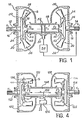
- the device shown in Figure 1 comprises a housing 10 defining two opposite parallel partitions through which pass two axially aligned rotating shafts 12 and 14, via two bearings 16 and 18 respectively.
- Each of the shafts 12 and 14 carries inside the housing 10 a system of weights 20 and 22 respectively.
- the weights systems 20 and 22 are constituted by plates 24 and 26 integral with the shafts 12 and 14 and carrying at their periphery weights 28 and 30, V-shaped, pivotally mounted around axes 32 and 34 which extend tangentially to the plates 24 and 26 and in radial planes with respect to the shafts 12 and 14.
- Each of the weights 28, 30 comprises a head 36, 38 in which is concentrated most of the mass of the corresponding weight and a tail 40 , 42 which extends radially inwards to co-operate with a roller 44, 46 with a movable element 48 slidably mounted in the housing 10.
- the element 48 is arranged co-axially at the shafts 12 and 14 between the systems of weights 20 and 22. Because of this arrangement, each of the weights systems 20 and 22 transforms the centrifugal force to which it is subjected due to the rotation of the corresponding shafts 12 and 14 into two opposite axial forces F 1 and F 2 respectively, applied to the moving assembly 48.
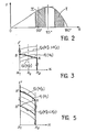
- FIG. 2 represents the variations in the torque C exerted by a system of counterweights of the type of systems 20 and 22 on a mobile assembly of the type of crew 48 as a function of the angle of oscillation of the counterweight .
- the stiffness dF / dx of the counterweight system is positive when the angle ⁇ remains between 0 and 100 ° and negative when the angle 8 is between 130 ° and 180 °, and it is substantially zero, when the angle 8 is close to 115 °.
- the sum of the stiffnesses of the two counterweight systems 20 and 22 is negative.
- this result is obtained by choosing two identical counterweight systems each having a negative stiffness corresponding for example to the operating zone I in FIG. 2.
- this result could also be obtained by using two different flyweight systems which can then either have a negative stiffness or have stiffnesses of opposite signs, the stiffness of the negative stiffness system then being greater in absolute value than the stiffness of the positive stiffness system (operating zones I and II in Figure 2).
- FIG. 3 represents the variations in the opposing forces F 1 and F 2 applied by the counterweight systems 20 and 22 on the moving assembly 48 in function displacement x of the latter.
- this first alternative embodiment of the invention which is characterized in that the sum of the stiffnesses of the counterweight systems 20 and 22 is negative, it will be seen that each of the positions of the moving assembly 48 between the extreme positions x 1 and x 2 that it is likely to occupy are stable positions.
- the speed of rotation N 1 of the shaft 12 is constant, so that a single curve represents the variation of the force F 1 as a function of the displacement x of the moving assembly 48 between its extreme positions x 1 and x 2 .
- the mobile assembly 48 remains at x 2 as long as the shaft 14 rotates at a speed N 2 lower than the speed N ' 2 for which the value of the force F 2 at x 2 becomes equal at the value of the force F, at x 2 .
- the speed of rotation N 2 of the shaft 14 is greater than the speed N ' 2
- the value of the force F 2 at x 2 becomes greater than the value of the force F 1 at x 2 , so that l mobile equipment 48 begins to move from x 2 to x 1 .
- the point representing the equilibrium of the moving assembly 48 then moves from A to B in FIG. 3.
- each intermediate position between the extreme positions x 1 and x 2 therefore defines a stable position for the moving element 48.
- Each of these stable positions corresponds, in the hypothesis that the speed Ni of the shaft 12 is constant, to a value given of the speed N 2 of the shaft 14, this value being between N ' 2 and N " 2 , N" 2 being the speed of the shaft 14 for which the value of the force F 2 in X 1 becomes equal to the value of the force F 1 in X 1 .
- each of the stable positions of the moving element 48 corresponding to a given value of the difference between the speeds N1 and N2.
- the stable nature of the intermediate positions of the moving element 48 is shown in FIG. 3 by the existence of points of intersection between the curves representative of the forces F 1 and F 2 when the speed of rotation of the shaft 14 is understood. between speeds N ' 2 and N " 2 .
- the position of the mobile assembly 48 between its extreme positions x 1 and x 2 is therefore representative of the difference existing between the rotational speeds of the shafts 12 and 14.
- This property can be used to measure this difference, using the moving equipment as an indicator, after performing a calibration.
- This property can also be used to control the speed of rotation of the shaft 14 to the speed of rotation of the shaft 12, or vice versa.
- the purpose of this slaving is to make the speed of the shaft 14 equal to the speed of the shaft 12.
- a detector 50 is housed in the housing 10 in order to detect the displacement of one or more marks 52 formed on the movable assembly 48.
- the signals delivered by the detector 50 are transmitted to a control system 54 ensuring the rotation drive of the shaft 14, so as to correct the latter's rotation speed by function of the information received by the detector 50.
- the counterweight systems 20 and 22 are moreover identical, so that the curves representative of the forces F 1 and F 2 are symmetrical and of opposite slope in FIG. 3.
- the mobile equipment 48 is therefore permanently maintained at equal distance from its extreme positions x 1 and x 2 , so that the point representing this balance is always located at x o in FIG. 3.
- the device shown in Figure 1 can be used to achieve more complex controls.
- this unmodified device can be used to make the speed of rotation of a regulated system equal to a multiple or a sub-multiple of the speed of rotation of the reference system.
- a multiplication or reduction mechanism for example with gears, is then placed between one of the systems and the corresponding shaft, 12 or 14, of the device according to the invention.
- Much more complex control systems can also be achieved, for example by using a hydraulic amplifier, the drawer of which would be constituted by the movable element 48, this element being itself mounted in a sleeve which is also movable.
- the movement of the sheath can be controlled for example by a counterweight detector of a conventional type, sensitive to the speed of rotation Ni of the shaft 12, if the speed of rotation N 2 of the shaft 14 must be controlled by this speed N 1 , or else by a pressure difference detector ⁇ P if speed N 2 must be controlled by this difference ⁇ P.
- the detection device is almost identical to the detection device shown in Figure 1, the only difference residing in the configuration of the weights 136 and 138 of the weights 120 and 122, oscillating around axes 132, 134 and having tails 140 and 142 terminated by a roller 144, 146.
- the shape of the weights 136 and 138 is such that the sum of the stiffnesses of each of the systems of weights 120 and 122 is positive. More specifically, in the embodiment shown, the systems 120 and 122 are identical and the stiffness of each of these systems is positive, which results from the fact that the angle 6 constituting the weights is less than about 100 °.
- each of the counterweight systems is of the type of zone II in FIG. 2.
- the angle 6 is formed as before, by the plane containing the axis of oscillation 132,134 of the massiotte 136, 138 and the center of gravity G ′ of the active mass of the counterweight and by the plane containing this same axis of oscillation and the roller 144, 146 which ensures contact between the tail 140, 142 of the counterweight and the moving assembly 148.
- FIG. 5 represents the variations of the opposite forces F 1 and F 2 exerted by each of the counterweight systems 120 and 122 on the mobile assembly 148 as a function of displacement x of the latter between its two extreme positions x 1 and x 2 .
- the device according to the invention operates in a completely different way from the variant shown in FIG. 1, since it can only occupy two stable positions which correspond to the extreme positions x 1 and x 2 .
- only one curve F 1 has been shown in FIG. 5 corresponding to a well-determined value N 1 of the speed of rotation of the shaft 112.
- the crew mobile 148 therefore moves abruptly to x 1 to reach the equilibrium point B 'in Figure 5. There is therefore no intermediate equilibrium point between points A and B', which is illustrated in FIG. 5 by the absence of intersection points between the curves representative of the forces F 1 and F 2 when the speed of rotation of the shaft 114 is greater than the speed N ′ 2 .
- the device has hysteresis.
- the return of the mobile assembly 148 at x 2 resulting from a reduction in the speed of rotation N 2 of the shaft 114 associated with the counterweight system 122 will only occur at point B "in FIG. 5 , that is to say when the speed N 2 will become lower than a speed N " 2 lower than the speed N ' 2 and for which the value of the force F 2 at x 1 becomes less than the value of the force F 1 and x 1 .
- the speed of rotation Ni of the shaft 112 is also variable, it can be said that the displacement of the mobile assembly 148 is then sensitive to a second threshold of the difference in the speeds Ni and N 2 .
- the moving element 148 then moves suddenly from x 1 to x 2 since to every displacement from x 1 to x 2 corresponds an increase in the difference between the force F 1 and the force F 2 .
- the device according to the invention can therefore be used to simply trigger a control system of an automation such as a microphone breaker 156 fixed to the housing 110.
- the microswitch 156 can be triggered for example, by means of a cam 158 carried by the moving element 148, when the difference between the rotational speeds of the shafts 122 and 114 exceeds the thresholds corresponding to the points A and B "in FIG. 5.
- the microswitch 156 can be replaced by any other control system such as a hydraulic or pneumatic valve.
Landscapes
- Engineering & Computer Science (AREA)
- Mechanical Engineering (AREA)
- General Engineering & Computer Science (AREA)
- Chemical & Material Sciences (AREA)
- Combustion & Propulsion (AREA)
- Power Engineering (AREA)
- Transmission Devices (AREA)
- Testing Of Balance (AREA)
- Control Of Position Or Direction (AREA)
Applications Claiming Priority (2)
| Application Number | Priority Date | Filing Date | Title |
|---|---|---|---|
| FR7925647 | 1979-10-16 | ||
| FR7925647A FR2468126A1 (fr) | 1979-10-16 | 1979-10-16 | Dispositif pour detecter une difference entre les vitesses de rotation de deux arbres tournants et application a une mesure ou a une commande d'asservissement |
Publications (2)
| Publication Number | Publication Date |
|---|---|
| EP0027407A1 EP0027407A1 (fr) | 1981-04-22 |
| EP0027407B1 true EP0027407B1 (fr) | 1986-01-29 |
Family
ID=9230707
Family Applications (1)
| Application Number | Title | Priority Date | Filing Date |
|---|---|---|---|
| EP80401413A Expired EP0027407B1 (fr) | 1979-10-16 | 1980-10-03 | Dispositif pour détecter une différence entre les vitesses de rotation de deux arbres tournants et application à une mesure ou à une commande d'asservissement |
Country Status (4)
| Country | Link |
|---|---|
| US (1) | US4369658A (show.php) |
| EP (1) | EP0027407B1 (show.php) |
| DE (1) | DE3071394D1 (show.php) |
| FR (1) | FR2468126A1 (show.php) |
Families Citing this family (2)
| Publication number | Priority date | Publication date | Assignee | Title |
|---|---|---|---|---|
| DE102004029475A1 (de) * | 2004-06-18 | 2006-01-26 | Henkel Kgaa | Neues enzymatisches Bleichsystem |
| US7382074B2 (en) * | 2006-01-30 | 2008-06-03 | Society For Research And Initiatives For Sustainable Technologies And Institutions | Alternate current power generator |
Citations (2)
| Publication number | Priority date | Publication date | Assignee | Title |
|---|---|---|---|---|
| US1856024A (en) * | 1923-03-21 | 1932-04-26 | Buchi Alfred | Controlling and regulating device for compound internal combustion engines with exhaust turbines |
| GB713944A (en) * | 1950-11-14 | 1954-08-18 | Alois Huwyler | A speed governor for electric motors |
Family Cites Families (9)
| Publication number | Priority date | Publication date | Assignee | Title |
|---|---|---|---|---|
| DE123632C (show.php) * | ||||
| US1754675A (en) * | 1930-04-15 | frank | ||
| GB271622A (en) * | 1926-04-28 | 1927-06-02 | Edward Ernest Tasker | Improvements in means for maintaining constant the speed of electrical motors |
| US2094196A (en) * | 1934-08-07 | 1937-09-28 | Lee & Northrup Company | Centrifugal governor |
| US2132911A (en) * | 1935-02-09 | 1938-10-11 | Wellton Otto Gottfried | Speed ratio indicator |
| US2423057A (en) * | 1944-05-29 | 1947-06-24 | Bendix Aviat Corp | Automatic brake control |
| US2958999A (en) * | 1957-04-18 | 1960-11-08 | Manitowoc Engincering Corp | Governor |
| US2861638A (en) * | 1957-09-19 | 1958-11-25 | Grovar Inc | Helicopter power plant system |
| US3699288A (en) * | 1971-03-08 | 1972-10-17 | Dana Corp | Speed responsive switch |
-
1979
- 1979-10-16 FR FR7925647A patent/FR2468126A1/fr active Granted
-
1980
- 1980-10-03 DE DE8080401413T patent/DE3071394D1/de not_active Expired
- 1980-10-03 EP EP80401413A patent/EP0027407B1/fr not_active Expired
- 1980-10-16 US US06/197,528 patent/US4369658A/en not_active Expired - Lifetime
Patent Citations (2)
| Publication number | Priority date | Publication date | Assignee | Title |
|---|---|---|---|---|
| US1856024A (en) * | 1923-03-21 | 1932-04-26 | Buchi Alfred | Controlling and regulating device for compound internal combustion engines with exhaust turbines |
| GB713944A (en) * | 1950-11-14 | 1954-08-18 | Alois Huwyler | A speed governor for electric motors |
Also Published As
| Publication number | Publication date |
|---|---|
| US4369658A (en) | 1983-01-25 |
| FR2468126A1 (fr) | 1981-04-30 |
| EP0027407A1 (fr) | 1981-04-22 |
| DE3071394D1 (en) | 1986-03-13 |
| FR2468126B1 (show.php) | 1983-07-29 |
Similar Documents
| Publication | Publication Date | Title |
|---|---|---|
| EP3360026B1 (fr) | Interface haptique hybride a rendu haptique ameliore | |
| WO2009141261A1 (fr) | Dispositif de mesure de couple transmis par un arbre de puissance | |
| EP0249559A1 (fr) | Procédé et dispositif d'asservissement en position d'un verin pneumatique | |
| EP0021258A1 (fr) | Dispositif électronique de commande du pontage d'un convertisseur de couple hydrodynamique et procédé de mise en oeuvre | |
| EP0027407B1 (fr) | Dispositif pour détecter une différence entre les vitesses de rotation de deux arbres tournants et application à une mesure ou à une commande d'asservissement | |
| LU85250A1 (fr) | Dispositif de transmission a rapport variable,utile en particulier pour les vehicules | |
| EP0206855B1 (fr) | Méthode et dispositif pour détecter un débit de fluide | |
| FR3031959A1 (fr) | Procede et dispositif de conjugaison d'organes de pilotage | |
| CA2447283C (fr) | Systeme de commandes de vol electriques pour aeronef comportant une detection de couplages oscillatoires de pilotage et organe de pilotage pour un tel systeme | |
| FR2620234A1 (fr) | Circuit de compensation en temperature pour accelerometre | |
| CA2051654C (fr) | Mecanisme de reglage fin de l'orientation et/ou de la position d'une charge utile | |
| FR2750182A1 (fr) | Agencement de plaque de pression pour embrayage a friction dans un vehicule automobile | |
| EP0027408B1 (fr) | Dispositif de déclenchement à masselottes | |
| EP3467612B1 (fr) | Dispositif de génération, par friction, de sensation d'efforts pour un système de commande de vol d'un aéronef | |
| EP2349832B1 (fr) | Ensemble de transmission d'efforts et ensemble de commande comprenant un tel ensemble | |
| EP3081484B1 (fr) | Systeme de commande d'un rotor de giravion, giravion equipe d'un tel systeme et methode de commande associee | |
| EP4316987B1 (fr) | Procede de determination de la position d'un dispositif d'actionnement, dispositif d'actionnement correspondant | |
| EP0006051A1 (fr) | Détecteur électrodynamométrique à seuil d'effort | |
| EP0346223B1 (fr) | Régulateur de vitesse pour véhicule automobile | |
| EP1647872A1 (fr) | Module de commande avec retour de force amélioré | |
| WO2024088547A1 (fr) | Dispositif de commande pour interface tactile capacitive | |
| WO2025008590A1 (fr) | Actionneur à double voie mécanique et procédé de détection d'un blocage d'une des voies mécaniques dudit actionneur | |
| WO2024200949A1 (fr) | Système de compensation de gravité apte à être installé dans une articulation d'un bras robot | |
| FR3024197A1 (fr) | Commande de boite de vitesses manuelle de vehicule automobile | |
| BE388235A (show.php) |
Legal Events
| Date | Code | Title | Description |
|---|---|---|---|
| PUAI | Public reference made under article 153(3) epc to a published international application that has entered the european phase |
Free format text: ORIGINAL CODE: 0009012 |
|
| 17P | Request for examination filed |
Effective date: 19801008 |
|
| AK | Designated contracting states |
Designated state(s): DE FR GB IT SE |
|
| ITF | It: translation for a ep patent filed | ||
| GRAA | (expected) grant |
Free format text: ORIGINAL CODE: 0009210 |
|
| AK | Designated contracting states |
Designated state(s): DE FR GB IT SE |
|
| REF | Corresponds to: |
Ref document number: 3071394 Country of ref document: DE Date of ref document: 19860313 |
|
| PLBE | No opposition filed within time limit |
Free format text: ORIGINAL CODE: 0009261 |
|
| STAA | Information on the status of an ep patent application or granted ep patent |
Free format text: STATUS: NO OPPOSITION FILED WITHIN TIME LIMIT |
|
| 26N | No opposition filed | ||
| ITTA | It: last paid annual fee | ||
| PGFP | Annual fee paid to national office [announced via postgrant information from national office to epo] |
Ref country code: SE Payment date: 19920910 Year of fee payment: 13 |
|
| PGFP | Annual fee paid to national office [announced via postgrant information from national office to epo] |
Ref country code: GB Payment date: 19920922 Year of fee payment: 13 |
|
| PGFP | Annual fee paid to national office [announced via postgrant information from national office to epo] |
Ref country code: FR Payment date: 19920924 Year of fee payment: 13 |
|
| PGFP | Annual fee paid to national office [announced via postgrant information from national office to epo] |
Ref country code: DE Payment date: 19921230 Year of fee payment: 13 |
|
| PG25 | Lapsed in a contracting state [announced via postgrant information from national office to epo] |
Ref country code: GB Effective date: 19931003 |
|
| PG25 | Lapsed in a contracting state [announced via postgrant information from national office to epo] |
Ref country code: SE Effective date: 19931004 |
|
| GBPC | Gb: european patent ceased through non-payment of renewal fee |
Effective date: 19931003 |
|
| PG25 | Lapsed in a contracting state [announced via postgrant information from national office to epo] |
Ref country code: FR Effective date: 19940630 |
|
| PG25 | Lapsed in a contracting state [announced via postgrant information from national office to epo] |
Ref country code: DE Effective date: 19940701 |
|
| REG | Reference to a national code |
Ref country code: FR Ref legal event code: ST |
|
| EUG | Se: european patent has lapsed |
Ref document number: 80401413.2 Effective date: 19940510 |