EP0027407B1 - Device for detecting a difference between the rotating speeds of two turning shafts and application to a measurement or a control servicing - Google Patents
Device for detecting a difference between the rotating speeds of two turning shafts and application to a measurement or a control servicing Download PDFInfo
- Publication number
- EP0027407B1 EP0027407B1 EP80401413A EP80401413A EP0027407B1 EP 0027407 B1 EP0027407 B1 EP 0027407B1 EP 80401413 A EP80401413 A EP 80401413A EP 80401413 A EP80401413 A EP 80401413A EP 0027407 B1 EP0027407 B1 EP 0027407B1
- Authority
- EP
- European Patent Office
- Prior art keywords
- difference
- mobile arrangement
- rotational speed
- fly
- speeds
- Prior art date
- Legal status (The legal status is an assumption and is not a legal conclusion. Google has not performed a legal analysis and makes no representation as to the accuracy of the status listed.)
- Expired
Links
Images
Classifications
-
- F—MECHANICAL ENGINEERING; LIGHTING; HEATING; WEAPONS; BLASTING
- F01—MACHINES OR ENGINES IN GENERAL; ENGINE PLANTS IN GENERAL; STEAM ENGINES
- F01D—NON-POSITIVE DISPLACEMENT MACHINES OR ENGINES, e.g. STEAM TURBINES
- F01D17/00—Regulating or controlling by varying flow
- F01D17/02—Arrangement of sensing elements
- F01D17/06—Arrangement of sensing elements responsive to speed
-
- F—MECHANICAL ENGINEERING; LIGHTING; HEATING; WEAPONS; BLASTING
- F02—COMBUSTION ENGINES; HOT-GAS OR COMBUSTION-PRODUCT ENGINE PLANTS
- F02D—CONTROLLING COMBUSTION ENGINES
- F02D25/00—Controlling two or more co-operating engines
- F02D25/02—Controlling two or more co-operating engines to synchronise speed
-
- H—ELECTRICITY
- H02—GENERATION; CONVERSION OR DISTRIBUTION OF ELECTRIC POWER
- H02P—CONTROL OR REGULATION OF ELECTRIC MOTORS, ELECTRIC GENERATORS OR DYNAMO-ELECTRIC CONVERTERS; CONTROLLING TRANSFORMERS, REACTORS OR CHOKE COILS
- H02P5/00—Arrangements specially adapted for regulating or controlling the speed or torque of two or more electric motors
- H02P5/46—Arrangements specially adapted for regulating or controlling the speed or torque of two or more electric motors for speed regulation of two or more dynamo-electric motors in relation to one another
- H02P5/48—Arrangements specially adapted for regulating or controlling the speed or torque of two or more electric motors for speed regulation of two or more dynamo-electric motors in relation to one another by comparing mechanical values representing the speeds
-
- F—MECHANICAL ENGINEERING; LIGHTING; HEATING; WEAPONS; BLASTING
- F05—INDEXING SCHEMES RELATING TO ENGINES OR PUMPS IN VARIOUS SUBCLASSES OF CLASSES F01-F04
- F05D—INDEXING SCHEME FOR ASPECTS RELATING TO NON-POSITIVE-DISPLACEMENT MACHINES OR ENGINES, GAS-TURBINES OR JET-PROPULSION PLANTS
- F05D2200/00—Mathematical features
- F05D2200/10—Basic functions
- F05D2200/11—Sum
Definitions
- the invention relates to a device making it possible to detect a difference between the speeds of rotation of two rotating shafts, in particular in order to display this difference in speeds on an appropriate device, to perform a servo-control of the speed of rotation of one of the shafts as a function of the speed of rotation of the other shaft, or of triggering an automatic mechanism when the difference between the speeds of rotation of the two shafts reaches only one determined.
- each of the speeds of rotation is determined by means of an independent speed-of-rotation detector comprising weights which rotate with the 'corresponding shaft and act against an opposing spring to move a moving element, and the moving elements of the two rotational speed detectors are connected by a mechanism comprising in most cases a system of levers and at least one cam.
- a device of this type is described in US Patent No. 2,861,638 of September 19, 1957 to R. A. Grosselfinger and AI.
- Such devices have the drawback of being complex, since they include two independent speed detectors each comprising a moving element and an opposing spring, as well as an intermediate mechanism connecting the moving elements of each of these detectors.
- GB-A-713 944 gives an example of the use of weights in a regulating system intended in this case for speed detection on a single shaft and which comprises a counter-thrust spring.
- the subject of the present invention is the production of a device using entirely mechanical and particularly simple weights, making it possible to compare the rotational speeds of two rotating shafts, such a device being usable either to display the difference between these speeds, or to achieve a precise and constant control according to a given law of one of the speeds as a function of the other, or finally, to trigger an automation such as a switch or a hydraulic or pneumatic valve when the difference between the speeds exceeds a threshold determined.
- the device of the aforementioned type is characterized, according to the invention in that the centrifugal masses are produced by weights pivoting about an axis of oscillation, having an angle 8, defined by the plane containing the axis of oscillation of the counterweight and the center of gravity of the active mass of the counterweight and the plane containing this same axis of oscillation and the roller which ensures the contact between the tail of the counterweight and the moving assembly, which is greater than 130 °, so that the sum of their respective stiffnesses is negative and the displacement obtained from the moving assembly is progressive and representative of the difference between the rotational speeds of the two shafts.
- the device according to the invention can then be used, either to display this difference on an appropriate device, or to achieve a control of one of the speeds by the other according to a precise law.
- the device according to the invention is characterized in that the centrifugal masses are produced by weights pivoting around an axis of oscillation, having an angle 6, defined by the plane containing the axis d oscillation of the counterweight and the center of gravity of the active mass of the counterweight and the plane containing this same axis of oscillation and the roller which ensures contact between the tail of the counterweight and the moving assembly, which is less than 100 ° so that the sum of their respective stiffnesses is positive and the moving assembly is sensitive to two determined values of the difference between the rotational speeds of the two shafts, to thus move suddenly between two extreme positions.
- the device can then be used to trigger an automatism, without there being an interaction from one regime to the other.
- the two usual rotational speed detectors are therefore replaced by a single device not comprising opposing springs and comprising only a movable assembly disposed directly between the two flyweight systems.
- the previously known ball system is replaced by a flyweight system having particular characteristics.
- Each of the flyweight systems acts as an opposing spring for the opposite flyweight system.
- the mechanism connecting each of the two moving parts in certain prior devices is eliminated.
- the device according to the invention can be used to carry out a measurement or a control, or to control an automation.
- the control can be carried out in different ways.
- the simplest relation consisting in making the speed of rotation N 2 of the regulated system equal to the speed of rotation N 1 of the reference system can be obtained by using two systems of identical weights and by equipping the mobile equipment with an amplifier capable of controlling the speed of rotation N 2 as a function of its displacements.
- the neutral position of this amplifier is made to coincide with the neutral position of the moving assembly obtained when N l -N 2 .
- This amplifier can be hydraulic, pneumatic, or electronic.
- the relation consisting in making the speed of rotation N 2 of the regulated system equal to a multiple or a sub-multiple of the speed of rotation Ni of the reference system can be realized by adding to the above device a mechanism such that a gear system between at least one of the systems and the corresponding shaft of the device according to the invention.
- a lever cooperating with the cam moves the sheath in which the mobile assembly of the device according to the invention moves.
- the moving equipment and the sheath constitute the detection element of the hydraulic amplifier controlling the regulated system rotating at speed N 2 .
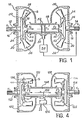
- the device shown in Figure 1 comprises a housing 10 defining two opposite parallel partitions through which pass two axially aligned rotating shafts 12 and 14, via two bearings 16 and 18 respectively.
- Each of the shafts 12 and 14 carries inside the housing 10 a system of weights 20 and 22 respectively.
- the weights systems 20 and 22 are constituted by plates 24 and 26 integral with the shafts 12 and 14 and carrying at their periphery weights 28 and 30, V-shaped, pivotally mounted around axes 32 and 34 which extend tangentially to the plates 24 and 26 and in radial planes with respect to the shafts 12 and 14.
- Each of the weights 28, 30 comprises a head 36, 38 in which is concentrated most of the mass of the corresponding weight and a tail 40 , 42 which extends radially inwards to co-operate with a roller 44, 46 with a movable element 48 slidably mounted in the housing 10.
- the element 48 is arranged co-axially at the shafts 12 and 14 between the systems of weights 20 and 22. Because of this arrangement, each of the weights systems 20 and 22 transforms the centrifugal force to which it is subjected due to the rotation of the corresponding shafts 12 and 14 into two opposite axial forces F 1 and F 2 respectively, applied to the moving assembly 48.
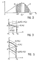
- FIG. 2 represents the variations in the torque C exerted by a system of counterweights of the type of systems 20 and 22 on a mobile assembly of the type of crew 48 as a function of the angle of oscillation of the counterweight .
- the stiffness dF / dx of the counterweight system is positive when the angle ⁇ remains between 0 and 100 ° and negative when the angle 8 is between 130 ° and 180 °, and it is substantially zero, when the angle 8 is close to 115 °.
- the sum of the stiffnesses of the two counterweight systems 20 and 22 is negative.
- this result is obtained by choosing two identical counterweight systems each having a negative stiffness corresponding for example to the operating zone I in FIG. 2.
- this result could also be obtained by using two different flyweight systems which can then either have a negative stiffness or have stiffnesses of opposite signs, the stiffness of the negative stiffness system then being greater in absolute value than the stiffness of the positive stiffness system (operating zones I and II in Figure 2).
- FIG. 3 represents the variations in the opposing forces F 1 and F 2 applied by the counterweight systems 20 and 22 on the moving assembly 48 in function displacement x of the latter.
- this first alternative embodiment of the invention which is characterized in that the sum of the stiffnesses of the counterweight systems 20 and 22 is negative, it will be seen that each of the positions of the moving assembly 48 between the extreme positions x 1 and x 2 that it is likely to occupy are stable positions.
- the speed of rotation N 1 of the shaft 12 is constant, so that a single curve represents the variation of the force F 1 as a function of the displacement x of the moving assembly 48 between its extreme positions x 1 and x 2 .
- the mobile assembly 48 remains at x 2 as long as the shaft 14 rotates at a speed N 2 lower than the speed N ' 2 for which the value of the force F 2 at x 2 becomes equal at the value of the force F, at x 2 .
- the speed of rotation N 2 of the shaft 14 is greater than the speed N ' 2
- the value of the force F 2 at x 2 becomes greater than the value of the force F 1 at x 2 , so that l mobile equipment 48 begins to move from x 2 to x 1 .
- the point representing the equilibrium of the moving assembly 48 then moves from A to B in FIG. 3.
- each intermediate position between the extreme positions x 1 and x 2 therefore defines a stable position for the moving element 48.
- Each of these stable positions corresponds, in the hypothesis that the speed Ni of the shaft 12 is constant, to a value given of the speed N 2 of the shaft 14, this value being between N ' 2 and N " 2 , N" 2 being the speed of the shaft 14 for which the value of the force F 2 in X 1 becomes equal to the value of the force F 1 in X 1 .
- each of the stable positions of the moving element 48 corresponding to a given value of the difference between the speeds N1 and N2.
- the stable nature of the intermediate positions of the moving element 48 is shown in FIG. 3 by the existence of points of intersection between the curves representative of the forces F 1 and F 2 when the speed of rotation of the shaft 14 is understood. between speeds N ' 2 and N " 2 .
- the position of the mobile assembly 48 between its extreme positions x 1 and x 2 is therefore representative of the difference existing between the rotational speeds of the shafts 12 and 14.
- This property can be used to measure this difference, using the moving equipment as an indicator, after performing a calibration.
- This property can also be used to control the speed of rotation of the shaft 14 to the speed of rotation of the shaft 12, or vice versa.
- the purpose of this slaving is to make the speed of the shaft 14 equal to the speed of the shaft 12.
- a detector 50 is housed in the housing 10 in order to detect the displacement of one or more marks 52 formed on the movable assembly 48.
- the signals delivered by the detector 50 are transmitted to a control system 54 ensuring the rotation drive of the shaft 14, so as to correct the latter's rotation speed by function of the information received by the detector 50.
- the counterweight systems 20 and 22 are moreover identical, so that the curves representative of the forces F 1 and F 2 are symmetrical and of opposite slope in FIG. 3.
- the mobile equipment 48 is therefore permanently maintained at equal distance from its extreme positions x 1 and x 2 , so that the point representing this balance is always located at x o in FIG. 3.
- the device shown in Figure 1 can be used to achieve more complex controls.
- this unmodified device can be used to make the speed of rotation of a regulated system equal to a multiple or a sub-multiple of the speed of rotation of the reference system.
- a multiplication or reduction mechanism for example with gears, is then placed between one of the systems and the corresponding shaft, 12 or 14, of the device according to the invention.
- Much more complex control systems can also be achieved, for example by using a hydraulic amplifier, the drawer of which would be constituted by the movable element 48, this element being itself mounted in a sleeve which is also movable.
- the movement of the sheath can be controlled for example by a counterweight detector of a conventional type, sensitive to the speed of rotation Ni of the shaft 12, if the speed of rotation N 2 of the shaft 14 must be controlled by this speed N 1 , or else by a pressure difference detector ⁇ P if speed N 2 must be controlled by this difference ⁇ P.
- the detection device is almost identical to the detection device shown in Figure 1, the only difference residing in the configuration of the weights 136 and 138 of the weights 120 and 122, oscillating around axes 132, 134 and having tails 140 and 142 terminated by a roller 144, 146.
- the shape of the weights 136 and 138 is such that the sum of the stiffnesses of each of the systems of weights 120 and 122 is positive. More specifically, in the embodiment shown, the systems 120 and 122 are identical and the stiffness of each of these systems is positive, which results from the fact that the angle 6 constituting the weights is less than about 100 °.
- each of the counterweight systems is of the type of zone II in FIG. 2.
- the angle 6 is formed as before, by the plane containing the axis of oscillation 132,134 of the massiotte 136, 138 and the center of gravity G ′ of the active mass of the counterweight and by the plane containing this same axis of oscillation and the roller 144, 146 which ensures contact between the tail 140, 142 of the counterweight and the moving assembly 148.
- FIG. 5 represents the variations of the opposite forces F 1 and F 2 exerted by each of the counterweight systems 120 and 122 on the mobile assembly 148 as a function of displacement x of the latter between its two extreme positions x 1 and x 2 .
- the device according to the invention operates in a completely different way from the variant shown in FIG. 1, since it can only occupy two stable positions which correspond to the extreme positions x 1 and x 2 .
- only one curve F 1 has been shown in FIG. 5 corresponding to a well-determined value N 1 of the speed of rotation of the shaft 112.
- the crew mobile 148 therefore moves abruptly to x 1 to reach the equilibrium point B 'in Figure 5. There is therefore no intermediate equilibrium point between points A and B', which is illustrated in FIG. 5 by the absence of intersection points between the curves representative of the forces F 1 and F 2 when the speed of rotation of the shaft 114 is greater than the speed N ′ 2 .
- the device has hysteresis.
- the return of the mobile assembly 148 at x 2 resulting from a reduction in the speed of rotation N 2 of the shaft 114 associated with the counterweight system 122 will only occur at point B "in FIG. 5 , that is to say when the speed N 2 will become lower than a speed N " 2 lower than the speed N ' 2 and for which the value of the force F 2 at x 1 becomes less than the value of the force F 1 and x 1 .
- the speed of rotation Ni of the shaft 112 is also variable, it can be said that the displacement of the mobile assembly 148 is then sensitive to a second threshold of the difference in the speeds Ni and N 2 .
- the moving element 148 then moves suddenly from x 1 to x 2 since to every displacement from x 1 to x 2 corresponds an increase in the difference between the force F 1 and the force F 2 .
- the device according to the invention can therefore be used to simply trigger a control system of an automation such as a microphone breaker 156 fixed to the housing 110.
- the microswitch 156 can be triggered for example, by means of a cam 158 carried by the moving element 148, when the difference between the rotational speeds of the shafts 122 and 114 exceeds the thresholds corresponding to the points A and B "in FIG. 5.
- the microswitch 156 can be replaced by any other control system such as a hydraulic or pneumatic valve.
Description
L'invention concerne un dispositif permettant de détecter une différence entre les vitesses de rotation de deux arbres tournants, afin notamment d'afficher cette différence de vitesses sur un appareil approprié, de réaliser un asservissement de la vitesse de rotation de l'un des arbres en fonction de la vitesse de rotation de l'autre arbre, ou de déclencher un automatisme lorsque la différence entre les vitesses de rotation des deux arbres atteint un seul déterminé.The invention relates to a device making it possible to detect a difference between the speeds of rotation of two rotating shafts, in particular in order to display this difference in speeds on an appropriate device, to perform a servo-control of the speed of rotation of one of the shafts as a function of the speed of rotation of the other shaft, or of triggering an automatic mechanism when the difference between the speeds of rotation of the two shafts reaches only one determined.
Généralement, lorsque la vitesse de rotation d'un arbre doit être asservie à la vitesse de rotation d'un autre arbre, chacune des vitesses de rotation est déterminée au moyen d'un détecteur de vitesse de rotation indépendant comprenant des masselottes qui tournent avec l'arbre correspondant et agissent à l'encontre d'un ressort antagoniste pour déplacer un équipage mobile, et les équipages mobiles des deux détecteurs de vitesses de rotation sont reliés par un mécanisme comportant dans la plupart des cas un système de leviers et au moins une came. Un dispositif de ce type est décrit dans le brevet des Etats-Unis d'Amérique No 2 861 638 du 19 Septembre 1957 de R. A. Grosselfinger et AI.Generally, when the speed of rotation of a shaft is to be controlled by the speed of rotation of another shaft, each of the speeds of rotation is determined by means of an independent speed-of-rotation detector comprising weights which rotate with the 'corresponding shaft and act against an opposing spring to move a moving element, and the moving elements of the two rotational speed detectors are connected by a mechanism comprising in most cases a system of levers and at least one cam. A device of this type is described in US Patent No. 2,861,638 of September 19, 1957 to R. A. Grosselfinger and AI.
De tels dispositifs présentent l'inconvénient d'être complexes, puisqu'ils comprennent deux détecteurs de vitesse indépendants comportant chacun un équipage mobile et un ressort antagoniste, ainsi qu'un mécanisme intermédiaire reliant les équipages mobiles de chacun de ces détecteurs.Such devices have the drawback of being complex, since they include two independent speed detectors each comprising a moving element and an opposing spring, as well as an intermediate mechanism connecting the moving elements of each of these detectors.
On connait également, par exemple du brevet des Etats Unis d'Amérique No. 1 856 024 du 10 Mars 1924, des dispositifs dans lesquels deux régulateurs à boules indépendants sont influencés mutuellement l'un par l'autre au travers d'un ressort de couplage. Cependant, ces dispositifs ne permettent pas de réaliser un asservissement entre les vitesses de rotation de deux arbres selon une relation précise, ce couplage n'ayant qu'un effet dynamique. Des systèmes à boules, qui se révèlent inadaptés pour les applications à grande précision sont également utilisés par le brevet GB-A-271.622. Celui ci montre un dispositif pour détecter une différence entre les vitesses de rotation de deux arbres tournants dans lequel deux systèmes régulateurs à masses centrifuges sont montés directement en opposition et agissent sur un équipage mobile disposé entre les systèmes régulateurs, ces derniers étant sensibles à la vitesse de rotation de chacun des arbres tournants, pour transformer la force centrifuge à laquelle ils sont soumis en deux forces opposées appliquées sur l'équipage mobile qu'ils déplacent de façon progressive en fonction de la différence entre les vitesses de rotation de deux arbres tournants.Also known, for example from United States patent No. 1,856,024 of March 10, 1924, devices in which two independent ball regulators are mutually influenced by each other through a spring coupling. However, these devices do not make it possible to produce a control between the rotational speeds of two shafts according to a precise relationship, this coupling having only a dynamic effect. Ball systems, which prove to be unsuitable for high precision applications are also used by patent GB-A-271,622. This shows a device for detecting a difference between the rotational speeds of two rotating shafts in which two regulating systems with centrifugal masses are mounted directly in opposition and act on a mobile assembly disposed between the regulating systems, the latter being sensitive to speed of rotation of each of the rotating shafts, to transform the centrifugal force to which they are subjected into two opposite forces applied to the mobile assembly which they move progressively as a function of the difference between the speeds of rotation of two rotating shafts.
Par ailleurs, GB-A-713 944 donne un exemple d'utilisation de masselottes dans un système régulateur destiné dans ce cas à une détection de régime sur un arbres unique et qui comporte un ressort de contre-poussée. Il est toutefois insuffisant de remplacer les boules du dispositif selon GB-A-271 622 par des masselottes d'un type couramment utilisé, en particulier du type dont GB-A-713 944 fournit un exemple, pour obtenir un dispositif à déplacement progressif analogue.Furthermore, GB-A-713 944 gives an example of the use of weights in a regulating system intended in this case for speed detection on a single shaft and which comprises a counter-thrust spring. However, it is not sufficient to replace the balls of the device according to GB-A-271 622 with weights of a type commonly used, in particular of the type of which GB-A-713 944 provides an example, in order to obtain a device with similar progressive displacement. .
Par ailleurs, on ne connait pas de mécanisme de détection de différence de vitesses de rotation utilisant des masselottes et permettant de réaliser un déclenchement franc d'un automatisme quelconque tel qu'un microrupteur ou un clapet.Furthermore, there is no known mechanism for detecting a difference in rotational speeds using weights and making it possible to trigger a frank triggering of any automatic mechanism such as a microswitch or a valve.
La présente invention a pour objet la réalisation d'un dispositif utilisant des masselottes entièrement mécanique et particulièrement simple, permettant de comparer les vitesses de rotation de deux arbres tournants, un tel dispositif pouvant être utilisé, soit pour afficher la différence entre ces vitesses, soit pour réaliser un asservissement précis et constant selon une loi donnée de l'une des vitesses en fonction de l'autre, soit enfin, pour déclencher un automatisme tel qu'un interrupteur ou un clapet hydraulique ou pneumatique lorsque la différence entre les vitesses dépasse un seuil déterminé.The subject of the present invention is the production of a device using entirely mechanical and particularly simple weights, making it possible to compare the rotational speeds of two rotating shafts, such a device being usable either to display the difference between these speeds, or to achieve a precise and constant control according to a given law of one of the speeds as a function of the other, or finally, to trigger an automation such as a switch or a hydraulic or pneumatic valve when the difference between the speeds exceeds a threshold determined.
Le dispositif du type précité est caractérisé, selon l'invention en ce que les masses centrifuges sont réalisées par des masselottes pivotant autour d'un axe d'oscillation, présentant un angle 8, défini par le plan contenant l'axe d'oscillation de la masselotte et le centre de gravité de la masse active de la masselotte et le plan contenant ce même axe d'oscillation et le galet qui assure le contact entre la queue de la masselotte et l'équipage mobile, qui soit supérieur à 130°, de telle sorte que la somme de leurs raideurs respectives est négative et que le déplacement obtenu de l'équipage mobile est progressif et représentatif de la différence entre les vitesses de rotation des deux arbres. Le dispositif selon l'invention peut alors être utilisé, soit pour afficher cette différence sur un appareil approprié, soit pour réaliser un asservissement de l'une des vitesses par l'autre selon une loi précise.The device of the aforementioned type is characterized, according to the invention in that the centrifugal masses are produced by weights pivoting about an axis of oscillation, having an angle 8, defined by the plane containing the axis of oscillation of the counterweight and the center of gravity of the active mass of the counterweight and the plane containing this same axis of oscillation and the roller which ensures the contact between the tail of the counterweight and the moving assembly, which is greater than 130 °, so that the sum of their respective stiffnesses is negative and the displacement obtained from the moving assembly is progressive and representative of the difference between the rotational speeds of the two shafts. The device according to the invention can then be used, either to display this difference on an appropriate device, or to achieve a control of one of the speeds by the other according to a precise law.
Selon une deuxième variante, le dispositif, selon l'invention, est caractérisé en ce que les masses centrifuges sont réalisées par des masselottes pivotant autour d'un axe d'oscillation, présentant un angle 6, défini par le plan contenant l'axe d'oscillation de la masselotte et le centre de gravité de la masse active de la masselotte et le plan contenant ce même axe d'oscillation et le galet qui assure le contact entre la queue de la masselotte et l'équipage mobile, qui soit inférieur à 100° de telle sorte que la somme de leurs raideurs respectives est positive et que l'équipage mobile est sensible à deux valeurs déterminées de la différence entre les vitesses de rotation des deux arbres, pour se déplacer ainsi de manière brusque entre deux positions extrêmes. Le dispositif peut alors être utilisé pour déclencher an automatisme, sans qu'il existe une interaction d'un régime sur l'autre.According to a second variant, the device according to the invention is characterized in that the centrifugal masses are produced by weights pivoting around an axis of oscillation, having an angle 6, defined by the plane containing the axis d oscillation of the counterweight and the center of gravity of the active mass of the counterweight and the plane containing this same axis of oscillation and the roller which ensures contact between the tail of the counterweight and the moving assembly, which is less than 100 ° so that the sum of their respective stiffnesses is positive and the moving assembly is sensitive to two determined values of the difference between the rotational speeds of the two shafts, to thus move suddenly between two extreme positions. The device can then be used to trigger an automatism, without there being an interaction from one regime to the other.
Conformément à l'invention, les deux détecteurs de vitesse de rotation usuels sont donc remplacés par un dispositif unique ne comprenant pas de ressorts antagonistes et ne comprenant qu'un équipage mobile disposé directement entre les deux systèmes de masselottes. Le système à boules précédemment connu est remplacé par un système à masselottes possédant des caractéristiques particulières. Chacun des systèmes de masselottes fait office de ressort antagoniste pour le système de masselottes opposé. Par ailleurs, le mécanisme reliant chacun des deux équipages mobiles dans certains dispositifs antérieurs est supprimé.According to the invention, the two usual rotational speed detectors are therefore replaced by a single device not comprising opposing springs and comprising only a movable assembly disposed directly between the two flyweight systems. The previously known ball system is replaced by a flyweight system having particular characteristics. Each of the flyweight systems acts as an opposing spring for the opposite flyweight system. Furthermore, the mechanism connecting each of the two moving parts in certain prior devices is eliminated.
Ce dispositif particulièrement simple peut donner lieu à de nombreuses applications. Ainsi, selon que la somme des raideurs des systèmes de masselottes est négative ou positive, le dispositif selon l'invention peut être utilisé pour réaliser une mesure ou un asservissement, ou pour commander un automatisme.This particularly simple device can give rise to numerous applications. Thus, depending on whether the sum of the stiffnesses of the counterweight systems is negative or positive, the device according to the invention can be used to carry out a measurement or a control, or to control an automation.
L'asservissement peut être effectué de différentes manières. Ainsi, la relation la plus simple consistant à rendre la vitesse de rotation N2 du système régulé égale à la vitesse de rotation N1 du système de référence peut être obtenue en utilisant deux systèmes de masselottes identiques et en équipant l'équipage mobile d'un amplificateur capable de commander la vitesse de rotation N2 en fonction de ses déplacements. On fait coïncider la position neutre de cet amplificateur avec la position neutre de l'équipage mobile obtenue quand Nl-N2. Cet amplificateur peut être hydraulique, pneumatique, ou électronique. De même, la relation consistant à rendre la vitesse de rotation N2 du système régulé égale à un multiple ou à un sous-multiple de la vitesse de rotation Ni du système de référence peut être réalisée an ajoutant au dispositif ci- dessus un mécanisme tel qu'un système d'engrenages entre au moins l'un des systèmes et l'arbre correspondant du dispositif selon l'invention. Une relation du type N2=f(N1) peut être obtenue en associant au dispositif selon l'invention un jeu de masselottes classique sensible à la vitesse de rotation Ni pour déplacer un organe muni d'une came déterminant la fonction à réaliser. Un levier coopérant avec la came déplace le forreau dans lequel se meut l'équipage mobile du dispositif selon l'invention. L'équipage mobile et le forreau constituent l'élément de détection de l'amplificateur hydraulique commandant le système régulé tournant à la vitesse N2. Ce jeu de masselottes classique peut être remplacé par un détecteur de différence de pressions AP classique, de telle sorte que la relation entre les vitesses de rotation N2 et Ni est du type N2=N1 ×f(ΔP).The control can be carried out in different ways. Thus, the simplest relation consisting in making the speed of rotation N 2 of the regulated system equal to the speed of rotation N 1 of the reference system can be obtained by using two systems of identical weights and by equipping the mobile equipment with an amplifier capable of controlling the speed of rotation N 2 as a function of its displacements. The neutral position of this amplifier is made to coincide with the neutral position of the moving assembly obtained when N l -N 2 . This amplifier can be hydraulic, pneumatic, or electronic. Similarly, the relation consisting in making the speed of rotation N 2 of the regulated system equal to a multiple or a sub-multiple of the speed of rotation Ni of the reference system can be realized by adding to the above device a mechanism such that a gear system between at least one of the systems and the corresponding shaft of the device according to the invention. A relationship of the type N 2 = f (N1) can be obtained by associating with the device according to the invention a set of conventional flyweights sensitive to the speed of rotation Ni for moving a member provided with a cam determining the function to be performed. A lever cooperating with the cam moves the sheath in which the mobile assembly of the device according to the invention moves. The moving equipment and the sheath constitute the detection element of the hydraulic amplifier controlling the regulated system rotating at speed N 2 . This classic set of weights can be replaced by a conventional AP pressure difference detector, so that the relationship between the rotational speeds N 2 and Ni is of the type N 2 = N 1 × f (ΔP).
On décrira maintenant, à titre d'exemple non limitatifs, deux modes de réalisation particuliers de l'invention en se référant aux dessins annexés, dans lesquels:
- - la figure 1 est une vue en coupe longitudinale d'un dispositif pour détecter une différence entre les vitesses de rotation des deux arbres tournants réalisé conformément aux enseignements de la présente invention, ce dispositif étant tel que la somme des raideurs des deux systèmes de masselotte est négative,
- - la figure 2 est une courbe représentant les variations du couple exercé par un système de masselottes sur un équipage mobile en fonction d'un angle défini entre la droite joignant le centre de gravité de la masse active de chaque masselotte à son axe de pivotement et le plan radial passant par cet axe de pivotement,
- - la figure 3 est un courbe représentant les variations des forces antagonistes exercées par les systèmes de masselottes sur l'équipage mobile en fonction du déplacement de cet équipage mobile dans le dispositif représenté sur la figure 1,
- - la figure 4 est une vue en coupe longitudinale similaire à la figure 1 représentant un autre mode de réalisation du dispositif selon l'invention, dans lequel la somme des raideurs des deux systèmes de masselottes est positive,
- - la figure 5 est une courbe représentant les variations des forces antagonistes exercées par les masselottes sur l'équipage mobile en fonction du déplacement de cet équipage dans le dispositif représenté sur la figure 4.
- - Figure 1 is a longitudinal sectional view of a device for detecting a difference between the rotational speeds of the two rotating shafts produced in accordance with the teachings of the present invention, this device being such that the sum of the stiffnesses of the two counterweight systems is negative,
- FIG. 2 is a curve representing the variations in the torque exerted by a system of weights on a movable assembly as a function of an angle defined between the straight line joining the center of gravity of the active mass of each weigher to its pivot axis and the radial plane passing through this pivot axis,
- FIG. 3 is a curve representing the variations in the opposing forces exerted by the counterweight systems on the mobile assembly as a function of the displacement of this mobile assembly in the device shown in FIG. 1,
- FIG. 4 is a view in longitudinal section similar to FIG. 1 showing another embodiment of the device according to the invention, in which the sum of the stiffnesses of the two counterweight systems is positive,
- FIG. 5 is a curve representing the variations in the opposing forces exerted by the counterweights on the mobile assembly as a function of the displacement of this assembly in the device shown in FIG. 4.
Le dispositif représenté sur la figure 1 comprend un boïtier 10 définissant deux cloisons parallèles opposées que traversent deux arbres tournants axialement alignés 12 et 14, par l'intermédiaire de deux paliers 16 et 18 respectivement. Chacun des arbres 12 et 14 porte à l'intérieur de boîtier 10 un système de masselottes 20 et 22 respectivement. Les systèmes de masselottes 20 et 22 sont constitués par des plateaux 24 et 26 solidaires des arbres 12 et 14 et portant à leur périphérie des masselottes 28 et 30, en forme de V, montées pivotantes autour d'axes 32 et 34 qui s'étendent tangentiellement aux plateaux 24 et 26 et dans des plans radiaux par rapport aux arbres 12 et 14. Chacune des masselottes 28, 30 comprend une tête 36, 38 dans laquelle est concentrée la plus grande partie de la masse de la masselotte correspondante et une queue 40, 42 qui s'étend radialement vers l'intérieur pour co-opérer par un galet 44, 46 avec un équipage mobile 48 monté coulissant dans le boîtier 10. L'équipage 48 est disposé co-axialement aux arbres 12 et 14 entre les systèmes de masselottes 20 et 22. En raison de cette disposition, chacun des systèmes de masselottes 20 et 22 transforme la force centrifuge à laquelle il est soumis en raison de la rotation des arbres 12 et 14 correspondants en deux efforts axiaux opposés F1 et F2 respectivement, appliqués à l'équipage mobile 48.The device shown in Figure 1 comprises a
On se référera maintenant à la figure 2 qui représente les variations du couple C exercé par un système de masselottes du type des systèmes 20 et 22 sur un équipage mobile du type de l'équipage 48 en fonction de l'angle d'oscillation de masselotte.Reference will now be made to FIG. 2 which represents the variations in the torque C exerted by a system of counterweights of the type of
On défini un angle 8 constitutif de la masselotte 28 ou 30 formé par le plan contenant l'axe d'oscillation 32, 34 de la masselotte et le centre de gravité G de la masse active de la masselotte et par le plan contenant ce même axe d'oscillation 32, 34 et le galet 44, 46 qui assure le contact entre la queue 40, 42 de la masselotte 28, 30 et l'équipage mobile 48. Lorsque les queues 40, 42 des masselottes 28, 30 sont dans leur position habituelle de travail, c'est à dire radiales, un calcul simple et connu de l'homme de métier montre que l'effort axial F exercé par les masselottes 28, 30 sur l'équipage mobile 48 est proportionnel au couple C et que la raideur dF/dx du système de masselottes, c'est à dire la variation de l'effort axial F exercé par ce système sur l'équipage mobile en fonction du déplacement x de cet équipage mobile, est proportionnelle à la pente de la courbe de la figure 2 au point correspondant à l'angle θ caractéristique des masselottes.We define an angle 8 constituting the
Ainsi, la raideur dF/dx du système de masselottes est positive lorsque l'angle θ reste compris entre 0 et 100° et négative lorsque l'angle 8 est compris entre 130° et 180°, et elle est sensiblement nulle, lorsque l'angle 8 est voisin de 115°.Thus, the stiffness dF / dx of the counterweight system is positive when the angle θ remains between 0 and 100 ° and negative when the angle 8 is between 130 ° and 180 °, and it is substantially zero, when the angle 8 is close to 115 °.
Dans la variante de réalisation représentée sur la figure 1, la somme des raideurs des deux systèmes de masselottes 20 et 22 est négative. Dans le cas de la figure 1, ce résultat est obtenu en choisissant deux systèmes de masselottes identiques et présentant chacun une raideur négative correspondant par exemple à la zone de fonctionnement I sur la figure 2. Cependant, ce résultat pourrait également être obtenu en utilisant deux systèmes de masselottes différents qui peuvent alors, soit présenter tous deux une raideur négative, soit présenter des raideurs de signes contraires, la raideur du système de raideur négative étant alors supérieure en valeur absolue à la raideur du système de raideur positive (zones de fonctionnement I et II sur la figure 2).In the variant embodiment shown in FIG. 1, the sum of the stiffnesses of the two
Afin de décrire le fonctionnement du dispositif représenté sur la figure 1, on se référera à la figure 3, qui représente les variations des forces antagonistes F1 et F2 appliquées par les systèmes de masselottes 20 et 22 sur l'équipage mobile 48 en fonction du déplacement x de ce dernier. Dans cette première variante de réalisation de l'invention, qui se caractérisé par le fait que la somme des raideurs des systèmes de masselottes 20 et 22 est négative, on verra que chacune des positions de l'équipage mobile 48 entre les positions extrêmes x1 et x2 qu'il est susceptible d'occuper sont des positions stables. Afin de faciliter la compréhension, on a supposé sur la figure 3 que la vitesse de rotation N1 de l'arbre 12 est constante, de telle sorte qu'une seule courbe représente la variation de la force F1 en fonction du déplacement x de l'équipage mobile 48 entre ses positions extrêmes x1 et x2.In order to describe the operation of the device represented in FIG. 1, reference will be made to FIG. 3, which represents the variations in the opposing forces F 1 and F 2 applied by the
Comme l'illustre la figure 3, l'équipage mobile 48 reste en x2 tant que l'arbre 14 tourne à une vitesse N2 inférieure à la vitesse N'2 pour laquelle la valeur de la force F2 en x2 devient égale à la valeur de la force F, en x2. Lorsque la vitesse de rotation N2 de l'arbre 14 est supérieure à la vitesse N'2, la valeur de la force F2 en x2 devient supérieure à la valeur de la force F1 en x2, de telle sorte que l'équipage mobile 48 commence à se déplacer de x2 vers x1. Le point représentatif de l'équilibre de l'équipage mobile 48 se déplace alors de A vers B sur la figure 3. Dès que les forces F1 et F2 deviennent égales, ce qui se produit à l'intersection des courbes représentatives des forces F1 et F2, l'équipage mobile 48 s'immobilise entre les positions extrêmes x1 et x2. Chaque position intermédiaire entre les positions extrêmes x1 et x2 définit donc une position stable pour l'équipage mobile 48. Chacune de ces positions stables correspond, dans l'hypothèse où la vitesse Ni de l'arbre 12 est constante, à une valeur donnée de la vitesse N2 de l'arbre 14, cette valeur étant comprise entre N'2 et N"2, N"2 étant la vitesse de l'arbre 14 pour laquelle la valeur de la force F2 en X1 devient égale à la valeur de la force F1 en X1. Cependant, lorsque les vitesses N1 et N2 sont toutes deux variables, Chacune des positions stables de l'équipage mobile 48 correspondant à une valeur donnée de la différence entre les vitesses N1 et N2. Le caractère stable des positions intermédiaires de l'équipage mobile 48 se manifeste sur la figure 3 par l'existence de points d'intersection entre les courbes représentatives des forces F1 et F2 lorsque la vitesse de rotation de l'arbre 14 est comprise entre les vitesses N'2 et N"2.As illustrated in FIG. 3, the
Cette caractéristique est donc due au fait que la somme des raideurs des systèmes de masselottes 20 et 22 est négative, dans cette première variante de l'invention. Bien entendu, lorsque le point représentatif de l'équilibre de l'équipage mobile 48 arrive en B, c'est à dire lorsque l'équipage mobile 48 arrive en x1, ce qui se produit lorsque la vitesse de rotation de l'arbre 14 est égale ou supérieure à N"2, toute augmentation de la force F2 n'apporte aucune modification de l'équilibre du dispositif.This characteristic is therefore due to the fact that the sum of the stiffnesses of the
Dans la première variante de l'invention représentée sur la figure 1, la position de l'équipage mobile 48 entre ses positions extrêmes x1 et x2 est donc représentative de la différence existant entre les vitesses de rotation des arbres 12 et 14.In the first variant of the invention shown in FIG. 1, the position of the
Cette propriété peut être utilisée pour réaliser une mesure de cette différence, en utilisant l'équipage mobile comme indicateur, après avoir effectué un étalonnage. Cette propriété peut également être utilisée pour réaliser un asservissement de la vitesse de rotation de l'arbre 14 à la vitesse de rotation de l'arbre 12, ou inversement. Dans le mode de réalisation représenté à titre d'exemple sur la figure 1, cet asservissement a pour but de rendre la vitesse de l'arbre 14 égale à la vitesse de l'arbre 12. A cet effet, un détecteur 50 est logé dans le boîtier 10 afin de détecter le déplacement d'un ou plusieurs repères 52 formés sur l'équipage mobile 48. Les signaux délivrés par le détecteur 50 sont transmis à un système de commande 54 assurant l'entraînement en rotation de l'arbre 14, de façon à corriger la vitesse de rotation de ce dernier en fonction des informations reçues par le détecteur 50. Les systèmes de masselottes 20 et 22 sont par ailleurs identiques, de telle sorte que les courbes représentatives des forces F1 et F2 sont symétriques et de pente opposée sur la figure 3. L'équipage mobile 48 est donc maintenu en permanence à égale distance de ses positions extrêmes x1 et x2, de telle sorte que le point représentatif de cet équilibre se trouve toujours situé en xo sur la figure 3.This property can be used to measure this difference, using the moving equipment as an indicator, after performing a calibration. This property can also be used to control the speed of rotation of the
Bien entendu, le dispositif représenté sur la figure 1 peut être utilisé pour réaliser des asservissements plus complexes. Ainsi, ce dispositif non modifié peut être utilisé pour rendre la vitesse de rotation d'un système régulé égale à un multiple ou à un sous-multiple de la vitesse de rotation du système de référence. Un mécanisme de multiplication ou de démultiplication par exemple à engrenages, est alors disposé entre l'un des systèmes et l'arbre correspondant, 12 ou 14, du dispositif selon l'invention. Des asservissements beaucoup plus complexes peuvent encore être réalisés, par exemple en utilisant un amplificateur hydraulique dont le tiroir serait constitué par l'équipage mobile 48, cet équipage étant lui-même monté dans un fourreau également mobile. Selon la fonction à réaliser, le déplacement du fourreau peut être commandé par exemple par un détecteur à masselottes d'un type classique, sensible à la vitesse de rotation Ni de l'arbre 12, si la vitesse de rotation N2 de l'arbre 14 doit être asservie à cette vitesse N1, ou encore par un détecteur de différence de pression ΔP si la vitesse N2 doit être asservie à cette différence ΔP. La fonction en elle-même est définie par une came solidaire de l'organe mobile du détecteur de vitesse ou du détecteur de différence de pression, sur laquelle prend appui un galet porté par un levier commandant les déplacements de l'amplificateur hydraulique. Des asservissements du type N2=N1×f(N1) ou N2=N1×f(P) peuvent ainsi être réalisés.Of course, the device shown in Figure 1 can be used to achieve more complex controls. Thus, this unmodified device can be used to make the speed of rotation of a regulated system equal to a multiple or a sub-multiple of the speed of rotation of the reference system. A multiplication or reduction mechanism, for example with gears, is then placed between one of the systems and the corresponding shaft, 12 or 14, of the device according to the invention. Much more complex control systems can also be achieved, for example by using a hydraulic amplifier, the drawer of which would be constituted by the
Dans la seconde variante de réalisation de l'invention représentée sur la figure 4, le dispositif de détection est à peu près identique au dispositif de détection représenté sur la figure 1, la seule différence résidant dans la configuration des masselottes 136 et 138 des systèmes de masselottes 120 et 122, oscillant autour d'axes 132, 134 et comportant des queues 140 et 142 terminées par un galet 144, 146. En effet, la forme des masselottes 136 et 138 est telle que la somme des raideurs de chacun des systèmes de masselottes 120 et 122 est positive. Plus précisément, dans le mode de réalisation représenté, les systèmes 120 et 122 sont identiques et la raideur de chacun de ces systèmes est positive, ce qui résulte du fait que l'angle 6 constitutif des masselottes est inférieur à environ 100°. La zone de fonctionnement de chacun des systèmes de masselottes est du type de la zone Il sur la figure 2. L'angle 6 est formé comme précédemment, par le plan contenant l'axe d'oscillation 132,134 de la masseiotte 136, 138 et le centre de gravité G' de la masse active de la masselotte et par le plan contenant ce même axe d'oscillation et le galet 144, 146 qui assure le contact entre la queue 140, 142 de la masselotte et l'équipage mobile 148.In the second embodiment of the invention shown in Figure 4, the detection device is almost identical to the detection device shown in Figure 1, the only difference residing in the configuration of the
On se référera maintenant à la figure 5, qui représente les variations des forces opposées F1 et F2 exercées par chacun des systèmes de masselottes 120 et 122 sur l'équipage mobile 148 en fonction de déplacement x de ce dernier entre ses deux positions extrêmes x1 et x2. Dans cette variante, le dispositif selon l'invention fonctionne de façon totalement différente de la variante représentée sur la figure 1, puisqu'il ne peut occuper que deux positions stables qui correspondent aux positions extrêmes x1 et x2. Pour simplifier, on n'a représenté sur la figure 5 qu'une seule courbe F1 correspondant à une valeur bien déterminée N1 de la vitesse de rotation de l'arbre 112.Reference will now be made to FIG. 5, which represents the variations of the opposite forces F 1 and F 2 exerted by each of the
En supposant que l'équipage mobile 148 occupe à l'origine la position x2, cet équipage mobile reste dans cette position jusqu'à ce que la valeur de la force F, en x2 devienne légèrement supérieure à la valeur de la force F1 en x2, c'est à dire au-delà du point A. Cette condition est réalisée lorsque la vitesse N2 de l'arbre 114 devient légèrement supérieure à une valeur N'2, ou, en supposant que la vitesse N1 de l'arbre 112 est également variable, lorsque la différence entre les vitesses N1 et N2 atteint une valeur déterminée par construction. L'équipage mobile 148 se déplace alors vers x1, ce qui a pour conséquence de faire augmenter la différence entre la force F2 et la force F1, et donc d'accélérer le déplacement de l'équipage mobile 148. L'équipage mobile 148 se déplace donc brutalement jusqu'en x1 pour attein- dre le point d'équilibre B' sur la figure 5. Il n'existe donc aucun point d'équilibre intermédiaire entre les points A et B', ce qui est illustré sur la figure 5 par l'absence de points d'intersection entre les courbes représentatives des forces F1 et F2 lorsque la vitesse de rotation de l'arbre 114 est supérieure à la vitesse N'2.Assuming that the moving
Dans cette variante de réalisation, le dispositif présente une hystérésis. En effet, le retour de l'équipage mobile 148 en x2 résultant d'une diminution de la vitesse de rotation N2 de l'arbre 114 associé au système de masselottes 122 n'interviendra qu'au point B" sur la figure 5, c'est à dire lorsque la vitesse N2 deviendra inférieure à une vitesse N"2 inférieure à la vitesse N'2 et pour laquelle la valeur de la force F2 en x1 devient inférieure à la valeur de la force F1 et x1. Si l'on suppose que la vitesse de rotation Ni de l'arbre 112 est également variable on peut dire que le déplacement de l'équipage mobile 148 est alors sensible à un second seuil de la différence des vitesses Ni et N2. L'équipage mobile 148 se déplace alors brutalement de x1 vers x2 étant donné qu'à tout déplacement de x1 vers x2 correspond une augmentation de la différence entre la force F1 et la force F2.In this variant embodiment, the device has hysteresis. In fact, the return of the
Dans la variante représentée sur la figure 4, le dispositif selon l'invention peut donc être utilisé pour déclencher de façon franche un système de commande d'un automatisme tel qu'un microrupteur 156 fixé au boîtier 110. Le microrupteur 156 peut être déclenché par exemple, au moyen d'une came 158 portée par l'équipage mobile 148, lorsque la différence entre les vitesses de rotations des arbres 122 et 114 dépasse les seuils correspondant aux points A et B" sur la figure 5. Bien entendu, le microrupteur 156 peut être remplace par tout autre système de commande tel qu'une valve hydraulique ou pneumatique.In the variant shown in Figure 4, the device according to the invention can therefore be used to frankly trigger a control system of an automation such as a
Les applications possibles du dispositif selon l'invention sont nombreuses et variées. Ainsi, la variante de réalisation de la figure 1 peut notamment être utilisée dans un réacteur double-corps pour mesurer les écarts entre les vitesses des deux arbres par rapport à une loi du type N2=k. N2 ou pour asservir la vitesse de l'un à suivre l'autre dans cette loi en agissant sur le débit de combustible, ou la section de tuyère, ou le calage des aubes du stator ou un autre paramètre déformable du réacteur.The possible applications of the device according to the invention are numerous and varied. Thus, the variant embodiment of FIG. 1 can in particular be used in a double-body reactor for measuring the differences between the speeds of the two shafts with respect to a law of the type N 2 = k. N 2 or to control the speed of one to follow the other in this law by acting on the fuel flow, or the nozzle section, or the setting of the stator vanes or another deformable parameter of the reactor.
Claims (7)
Applications Claiming Priority (2)
| Application Number | Priority Date | Filing Date | Title |
|---|---|---|---|
| FR7925647 | 1979-10-16 | ||
| FR7925647A FR2468126A1 (en) | 1979-10-16 | 1979-10-16 | DEVICE FOR DETECTING A DIFFERENCE BETWEEN THE ROTATIONAL SPEED OF TWO ROTATING TREES AND APPLICATION TO A MEASURE OR TO A CONTROL OF SERVICING |
Publications (2)
| Publication Number | Publication Date |
|---|---|
| EP0027407A1 EP0027407A1 (en) | 1981-04-22 |
| EP0027407B1 true EP0027407B1 (en) | 1986-01-29 |
Family
ID=9230707
Family Applications (1)
| Application Number | Title | Priority Date | Filing Date |
|---|---|---|---|
| EP80401413A Expired EP0027407B1 (en) | 1979-10-16 | 1980-10-03 | Device for detecting a difference between the rotating speeds of two turning shafts and application to a measurement or a control servicing |
Country Status (4)
| Country | Link |
|---|---|
| US (1) | US4369658A (en) |
| EP (1) | EP0027407B1 (en) |
| DE (1) | DE3071394D1 (en) |
| FR (1) | FR2468126A1 (en) |
Families Citing this family (2)
| Publication number | Priority date | Publication date | Assignee | Title |
|---|---|---|---|---|
| DE102004029475A1 (en) * | 2004-06-18 | 2006-01-26 | Henkel Kgaa | New enzymatic bleaching system |
| US7382074B2 (en) * | 2006-01-30 | 2008-06-03 | Society For Research And Initiatives For Sustainable Technologies And Institutions | Alternate current power generator |
Citations (2)
| Publication number | Priority date | Publication date | Assignee | Title |
|---|---|---|---|---|
| US1856024A (en) * | 1923-03-21 | 1932-04-26 | Buchi Alfred | Controlling and regulating device for compound internal combustion engines with exhaust turbines |
| GB713944A (en) * | 1950-11-14 | 1954-08-18 | Alois Huwyler | A speed governor for electric motors |
Family Cites Families (9)
| Publication number | Priority date | Publication date | Assignee | Title |
|---|---|---|---|---|
| US1754675A (en) * | 1930-04-15 | frank | ||
| DE123632C (en) * | ||||
| GB271622A (en) * | 1926-04-28 | 1927-06-02 | Edward Ernest Tasker | Improvements in means for maintaining constant the speed of electrical motors |
| US2094196A (en) * | 1934-08-07 | 1937-09-28 | Lee & Northrup Company | Centrifugal governor |
| US2132911A (en) * | 1935-02-09 | 1938-10-11 | Wellton Otto Gottfried | Speed ratio indicator |
| US2423057A (en) * | 1944-05-29 | 1947-06-24 | Bendix Aviat Corp | Automatic brake control |
| US2958999A (en) * | 1957-04-18 | 1960-11-08 | Manitowoc Engincering Corp | Governor |
| US2861638A (en) * | 1957-09-19 | 1958-11-25 | Grovar Inc | Helicopter power plant system |
| US3699288A (en) * | 1971-03-08 | 1972-10-17 | Dana Corp | Speed responsive switch |
-
1979
- 1979-10-16 FR FR7925647A patent/FR2468126A1/en active Granted
-
1980
- 1980-10-03 EP EP80401413A patent/EP0027407B1/en not_active Expired
- 1980-10-03 DE DE8080401413T patent/DE3071394D1/en not_active Expired
- 1980-10-16 US US06/197,528 patent/US4369658A/en not_active Expired - Lifetime
Patent Citations (2)
| Publication number | Priority date | Publication date | Assignee | Title |
|---|---|---|---|---|
| US1856024A (en) * | 1923-03-21 | 1932-04-26 | Buchi Alfred | Controlling and regulating device for compound internal combustion engines with exhaust turbines |
| GB713944A (en) * | 1950-11-14 | 1954-08-18 | Alois Huwyler | A speed governor for electric motors |
Also Published As
| Publication number | Publication date |
|---|---|
| US4369658A (en) | 1983-01-25 |
| FR2468126B1 (en) | 1983-07-29 |
| EP0027407A1 (en) | 1981-04-22 |
| FR2468126A1 (en) | 1981-04-30 |
| DE3071394D1 (en) | 1986-03-13 |
Similar Documents
| Publication | Publication Date | Title |
|---|---|---|
| EP3069045B1 (en) | Simplified torsion damping device having a pendulum | |
| EP2288890A1 (en) | Device for measuring the torque transmitted by a power shaft | |
| EP3360026A1 (en) | Hybrid haptic interface with improved haptic feedback | |
| EP0249559A1 (en) | Method and device for the position control of a pneumatic actuator | |
| EP0021258A1 (en) | Electronic device for controlling the lock-up of a hydrodynamic torque converter, and method of operation | |
| EP0027407B1 (en) | Device for detecting a difference between the rotating speeds of two turning shafts and application to a measurement or a control servicing | |
| LU85250A1 (en) | VARIABLE RATIO TRANSMISSION DEVICE, ESPECIALLY USEFUL FOR VEHICLES | |
| EP0206855B1 (en) | Method and device for detecting a fluid flow | |
| FR3031959A1 (en) | METHOD AND DEVICE FOR CONJUGATING CONTROL RODS | |
| EP1420320B1 (en) | Aircraft fly-by-wire system with detection of pilot-induced oscillatory couplings, and control element for such a system | |
| CA2051654C (en) | Payload orientation and/or position fine-adjusting mechanism | |
| FR2750182A1 (en) | PRESSURE PLATE ARRANGEMENT FOR FRICTION CLUTCH IN A MOTOR VEHICLE | |
| EP3467612B1 (en) | Device for generating force sensation, by friction, for a flight control system of an aircraft | |
| EP0027408B1 (en) | Fly-weight unlatching device | |
| EP3081484B1 (en) | A system for controlling a rotorcraft rotor, a rotorcraft fitted with such a system, and an associated control method | |
| WO2024088547A1 (en) | Control device for a capacitive touch interface | |
| EP2349832B1 (en) | Force transmission unit and control unit including such a unit | |
| WO2023079247A1 (en) | Force application device for a control stick, control stick, method, program and aircraft | |
| EP0346223B1 (en) | Speed regulator for an automotive vehicle | |
| EP1647872A1 (en) | Control element having an improved force feedback mechanism | |
| EP0109885B1 (en) | Large angle cardan joint | |
| FR3024197A1 (en) | MANUAL GEARBOX CONTROL OF A MOTOR VEHICLE | |
| BE388235A (en) | ||
| FR2855282A1 (en) | Interfaces switch releasing force controlling process, involves determining two components of releasing force and calculating and controlling releasing force to be applied for each of three switches from two components | |
| EP3165793A1 (en) | Control device for linear actuator, associated actuator, method and use |
Legal Events
| Date | Code | Title | Description |
|---|---|---|---|
| PUAI | Public reference made under article 153(3) epc to a published international application that has entered the european phase |
Free format text: ORIGINAL CODE: 0009012 |
|
| 17P | Request for examination filed |
Effective date: 19801008 |
|
| AK | Designated contracting states |
Designated state(s): DE FR GB IT SE |
|
| ITF | It: translation for a ep patent filed |
Owner name: BARZANO' E ZANARDO MILANO S.P.A. |
|
| GRAA | (expected) grant |
Free format text: ORIGINAL CODE: 0009210 |
|
| AK | Designated contracting states |
Designated state(s): DE FR GB IT SE |
|
| REF | Corresponds to: |
Ref document number: 3071394 Country of ref document: DE Date of ref document: 19860313 |
|
| PLBE | No opposition filed within time limit |
Free format text: ORIGINAL CODE: 0009261 |
|
| STAA | Information on the status of an ep patent application or granted ep patent |
Free format text: STATUS: NO OPPOSITION FILED WITHIN TIME LIMIT |
|
| 26N | No opposition filed | ||
| ITTA | It: last paid annual fee | ||
| PGFP | Annual fee paid to national office [announced via postgrant information from national office to epo] |
Ref country code: SE Payment date: 19920910 Year of fee payment: 13 |
|
| PGFP | Annual fee paid to national office [announced via postgrant information from national office to epo] |
Ref country code: GB Payment date: 19920922 Year of fee payment: 13 |
|
| PGFP | Annual fee paid to national office [announced via postgrant information from national office to epo] |
Ref country code: FR Payment date: 19920924 Year of fee payment: 13 |
|
| PGFP | Annual fee paid to national office [announced via postgrant information from national office to epo] |
Ref country code: DE Payment date: 19921230 Year of fee payment: 13 |
|
| PG25 | Lapsed in a contracting state [announced via postgrant information from national office to epo] |
Ref country code: GB Effective date: 19931003 |
|
| PG25 | Lapsed in a contracting state [announced via postgrant information from national office to epo] |
Ref country code: SE Effective date: 19931004 |
|
| GBPC | Gb: european patent ceased through non-payment of renewal fee |
Effective date: 19931003 |
|
| PG25 | Lapsed in a contracting state [announced via postgrant information from national office to epo] |
Ref country code: FR Effective date: 19940630 |
|
| PG25 | Lapsed in a contracting state [announced via postgrant information from national office to epo] |
Ref country code: DE Effective date: 19940701 |
|
| REG | Reference to a national code |
Ref country code: FR Ref legal event code: ST |
|
| EUG | Se: european patent has lapsed |
Ref document number: 80401413.2 Effective date: 19940510 |